
Please read this instructions before operating the device and retain them for future reference.
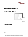
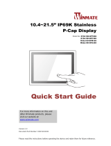
IP65 Stainless P-Cap
15/17/19/21.5” Panel PC
Intel® Core™ i5-7200U Kaby Lake
Model No.:
R15IK3S-SPC3
R17IK3S-SPA1
R19IK3S-SPM1
W22IK3S-SPA3
User Manual
Version 1.0

2
IP65 Stainless P-Cap Panel PC User Manual
Contents
Preface ................................................................................................................................. 4
About This User Manual ..................................................................................................... 9
Chapter 1: Introduction .................................................................................................... 10
1.1 Introduction ........................................................................................................ 11
1.2 Product Features ................................................................................................ 11
1.3 Package Content ................................................................................................ 12
1.4 Connector Placement ......................................................................................... 13
1.5 Physical Buttons and LED Indicators ................................................................. 13
1.6 Schematics and Dimensions .............................................................................. 14
1.6.1 Dimensions 15" ......................................................................................... 14
1.6.2 Dimensions 17” ......................................................................................... 14
1.6.3 Dimensions 19” ......................................................................................... 15
1.6.4 Dimensions 21.5” ...................................................................................... 15
Chapter 2: Getting Started ........................................................................................ 16
2.1 Powering On ...................................................................................................... 17
2.1.1 AC Adapter Components .......................................................................... 17
2.1.2 Power Considerations............................................................................... 18
2.1.3 Power Consumption ................................................................................. 18
2.1.4 Turning On/ Off Your Device .................................................................... 18
2.2 Connector Pin Assignments ............................................................................... 19
2.2.1 Power Cable ............................................................................................. 19
2.2.2 Serial Cable .............................................................................................. 20
2.2.3 Ethernet Cable .......................................................................................... 21
2.2.4 USB 2.0 Cable .......................................................................................... 22
2.3 Cleaning the Monitor .......................................................................................... 23
Chapter 3: Mounting .................................................................................................... 24
3.1 Cable Mounting Considerations ......................................................................... 25
3.2 Safety Precautions ............................................................................................. 25
3.3 VESA Mount ....................................................................................................... 26
3.4 Yoke Mount ........................................................................................................ 27
Chapter 4: Operating the Device ............................................................................. 28
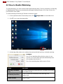
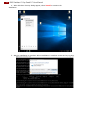
4.1 Operating System ............................................................................................... 29
4.2 Multi-Touch ........................................................................................................ 29

3
Preface
4.3 How to Enable Watchdog ................................................................................... 30
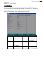
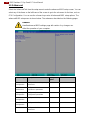
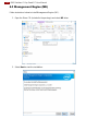
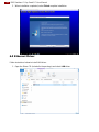
Chapter 5: Insyde BIOS Setup .................................................................................. 31
5.1 How and When to Use BIOS Setup.................................................................... 32
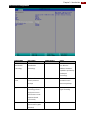
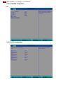
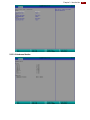
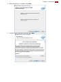
5.2 BIOS Functions .................................................................................................. 33
5.2.1 Main Menu ................................................................................................ 33
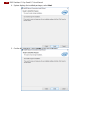
5.2.2 Advanced .................................................................................................. 34
5.2.3 Boot .......................................................................................................... 49
3.2.3 Security ..................................................................................................... 52
5.2.4 Power ....................................................................................................... 53
5.2.5 Exit ........................................................................................................... 54
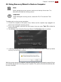
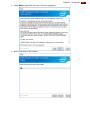
5.3 Using Recovery Wizard to Restore Computer .................................................... 55
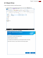
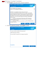
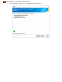
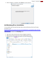
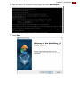
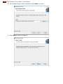
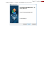
Chapter 6: Driver Installation ................................................................................... 56
6.1 Chipset Driver..................................................................................................... 57
6.2 Graphic Driver .................................................................................................... 59
6.3 Management Engine (ME) ................................................................................. 64
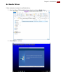
6.4 Audio Driver ....................................................................................................... 67
6.5 Ethernet Driver ................................................................................................... 68
6.6 Watchdog Driver Installation .............................................................................. 71
Chapter 6: Technical Support ................................................................................... 76
7.1 Software Developer Support .............................................................................. 77
7.2 Problem Report Form ......................................................................................... 77
Appendix A: Product Specifications ............................................................................... 78

4
IP65 Stainless P-Cap Panel PC User Manual
Preface
Copyright Notice
No part of this document may be reproduced, copied, translated, or transmitted in any form or
by any means, electronic or mechanical, for any purpose, without the prior written permission
of the original manufacturer.
Trademark Acknowledgement
Brand and product names are trademarks or registered trademarks of their respective owners.
Disclaimer
We reserve the right to make changes, without notice, to any product, including circuits and/or
software described or contained in this manual in order to improve design and/or performance.
We assume no responsibility or liability for the use of the described product(s) conveys no
license or title under any patent, copyright, or masks work rights to these products, and make
no representations or warranties that these products are free from patent, copyright, or mask
work right infringement, unless otherwise specified. Applications that are described in this
manual are for illustration purposes only. We make no representation or guarantee that such
application will be suitable for the specified use without further testing or modification.
Warranty
Our warranty guarantees that each of its products will be free from material and workmanship
defects for a period of one year from the invoice date. If the customer discovers a defect, we
will, at his/her option, repair or replace the defective product at no charge to the customer,
provide it is returned during the warranty period of one year, with transportation charges
prepaid. The returned product must be properly packaged in its original packaging to obtain
warranty service. If the serial number and the product shipping data differ by over 30 days, the
in-warranty service will be made according to the shipping date. In the serial numbers the third
and fourth two digits give the year of manufacture, and the fifth digit means the month (e. g.,
with A for October, B for November and C for December).
For example, the serial number 1W18Axxxxxxxx means October of year 2018.
Customer Service
We provide a service guide for any problem by the following steps: First, visit the website of
our distributor to find the update information about the product. Second, contact with your
distributor, sales representative, or our customer service center for technical support if you
need additional assistance.
You may need the following information ready before you call:
Product serial number
Software (OS, version, application software, etc.)
Description of complete problem
The exact wording of any error messages
In addition, free technical support is available from our engineers every business day. We are
always ready to give advice on application requirements or specific information on the
installation and operation of any of our products.

5
Preface
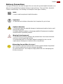
Advisory Conventions
Four types of advisories are used throughout the user manual to provide helpful information or to
alert you to the potential for hardware damage or personal injury. These are Notes, Important,
Cautions, and Warnings. The following is an example of each type of advisory.
Note:
A note is used to emphasize helpful information
Important:
An important note indicates information that is important for you to know.
Caution/ Attention
A Caution alert indicates potential damage to hardware and explains how to avoid
the potential problem.
Une alerte d’attention indique un dommage possible à l’équipement et explique
comment éviter le problème potentiel.
Warning!/ Avertissement!
An Electrical Shock Warning indicates the potential harm from electrical hazards
and how to avoid the potential problem.
Un Avertissement de Choc Électrique indique le potentiel de chocs sur des
emplacements électriques et comment éviter ces problèmes.
Alternating Current Mise à le terre !
The Protective Conductor Terminal (Earth Ground) symbol indicates the potential
risk of serious electrical shock due to improper grounding.
Le symbole de Mise à Terre indique le risqué potential de choc électrique grave
à la terre incorrecte.

6
IP65 Stainless P-Cap Panel PC User Manual
Safety Information
Warning!/ Avertissement!
Always completely disconnect the power cord from your chassis whenever you
work with the hardware. Do not make connections while the power is on.
Sensitive electronic components can be damaged by sudden power surges.
Only experienced electronics personnel should open the PC chassis.
Toujours débrancher le cordon d’alimentation du chassis lorsque vous travaillez
sur celui-ci. Ne pas brancher de connections lorsque l’alimentation est
présente. Des composantes électroniques sensibles peuvent être
endommagées par des sauts d’alimentation. Seulement du personnel
expérimenté devrait ouvrir ces chassis.
Caution/ Attention
Always ground yourself to remove any static charge before touching the CPU
card. Modern electronic devices are very sensitive to static electric charges. As a
safety precaution, use a grounding wrist strap at all times. Place all electronic
components in a static-dissipative surface or static-shielded bag when they are
not in the chassis.
Toujours verifier votre mise à la terre afin d’éliminer toute charge statique avant
de toucher la carte CPU. Les équipements électroniques moderns sont très
sensibles aux décharges d’électricité statique. Toujours utiliser un bracelet de
mise à la terre comme précaution. Placer toutes les composantes électroniques
sur une surface conçue pour dissiper les charge, ou dans un sac anti-statique
lorsqu’elles ne sont pas dans le chassis.
For your safety carefully read all the safety instructions before using the device. Keep this user
manual for future reference.
Always disconnect this equipment from any AC outlet before cleaning. Do not use liquid or
spray detergents for cleaning. Use a damp cloth.
For pluggable equipment, the power outlet must be installed near the equipment and must
be easily accessible.
Keep this equipment away from humidity.
Put this equipment on a reliable surface during installation. Dropping it or letting it fall could
cause damage.
The openings on the enclosure are for air convection and to protect the equipment from
overheating.
Caution/Attention
Do not cover the openings!
Ne pas couvrir les ouvertures!
Before connecting the equipment to the power outlet make sure the voltage of the power
source is correct.
Position the power cord so that people cannot step on it. Do not place anything over the
power cord.
If the equipment is not used for a long time, disconnect it from the power source to avoid
damage by transient over-voltage.
Never pour any liquid into an opening. This could cause fire or electrical shock.
Never open the equipment. For safety reasons, only qualified service personnel should
open the equipment.
All cautions and warnings on the equipment should be noted.

7
Preface
*Let service personnel to check the equipment in case any of the following
problems appear:
o The power cord or plug is damaged.
o Liquid has penetrated into the equipment.
o The equipment has been exposed to moisture.
o The equipment does not work well or you cannot get it to work according to
the user manual.
o The equipment has been dropped and damaged.
o The equipment has obvious signs of breakage.
Do not leave this equipment in an uncontrolled environment where the storage
temperature is below -20°C (-4°F) or above 60°C (140°F). It may damage the
equipment.
Caution/Attention
Use the recommended mounting apparatus to avoid risk of injury.
Utiliser l’appareil de fixation recommandé pour éliminer le risque de
blessure.
Warning!/ Avertissement!
Only use the connection cords that come with the product. When in doubt,
please contact the manufacturer.
Utiliser seulement les cordons d’alimentation fournis avec le produit. Si
vous doutez de leur provenance, contactez le manufacturier.
Warning!/ Avertissement!
Always ground yourself against electrostatic damage to the device.
Toujours vérifier votre mise à la terre afin que l’équipement ne se décharge
pas sur vous.
Cover workstations with approved anti-static material. Use a wrist strap connected
to a work surface and properly grounded tools and equipment.
Use anti-static mats, heel straps, or air ionizer for added protection.
Avoid contact with pins, leads, or circuitry.
Turn off power and input signals before inserting and removing connectors or test
equipment.
Keep the work area free of non-conductive materials, such as ordinary plastic
assembly aids and Styrofoam.
Use filed service tools, such as cutters, screwdrivers, and vacuum cleaners that
are conductive.
Always put drivers and PCB’s component side on anti-static foam.

8
IP65 Stainless P-Cap Panel PC User Manual
Important Information
Federal Communications Commission Radio Frequency Interface Statement
This device complies with part 15 FCC rules.
Operation is subject to the following two conditions:
This device may not cause harmful interference.
This device must accept any interference received including
interference that may cause undesired operation.
This equipment has been tested and found to comply with the limits for a class "B" digital
device, pursuant to part 15 of the FCC rules. These limits are designed to provide reasonable
protection against harmful interference when the equipment is operated in a commercial
environment. This equipment generates, uses, and can radiate radio frequency energy and, if
not installed and used in accordance with the instruction manual, may cause harmful
interference to radio communications. Operation of this equipment in a residential area is likely
to cause harmful interference in which case the user will be required to correct the interference
at him own expense.
EC Declaration of Conformity
This equipment is in conformity with the requirement of the
following EU legislations and harmonized standards. Product also
complies with the Council directions.
Electromagnetic Compatibility Directive (2014/30/EU)
EN55024: 2010 EN 55022: 2010 Class B
o IEC61000-4-2: 2009
o IEC61000-4-3: 2006+A1: 2007+A2: 2010
o IEC61000-4-4: 2012
o IEC61000-4-5: 2014
o IEC61000-4-6: 2013
o IEC61000-4-8: 2010
o IEC61000-4-11: 2004
EN55022: 2010/AC:2011
EN61000-3-2:2014
EN61000-3-3:2013
Low Voltage Directive (2014/35/EU)
EN 60950-1:2006/A11:2009/A1:2010/A12:2011/ A2:2013

9
About This User Manual
About This User Manual
This User Manual provides information about using the Winmate® IP65 Stainless P-Cap Panel PC
with Intel® Core™ i5-7200U Kaby Lake processor. This User Manual applies to the IP65 Flat
Stainless P-Cap Panel PC – R15IK3S-SPC3, R17IK3S-SPA1, R19IK3S-SPM1, and W22IK3S-
SPA3.
The documentation set for the IP65 Flat Stainless P-Cap Panel PC provides information for
specific user needs, and includes:
IP65 Stainless P-Cap Panel PC User Manual – contains detailed description on how to
use the Panel PC, its components and features.
IP65 Stainless P-Cap Panel PC Quick Start Guide - contains detailed description on how
to use the Panel PC, its components and features.
Note:
Some pictures in this guide are samples and can differ from actual product.
Document Revision History
Version
Date
Note
1.0
13-Sept-2018
Initial document release

10
IP65 Stainless P-Cap Panel PC User Manual
Chapter 1: Introduction
This chapter gives you product overview, describes features and
hardware specification. You will find all accessories that come
with the Panel PC in the packing list. Mechanical dimensions and
drawings included in this chapter.

11
Chapter 1: Introduction
1.1 Introduction
Congratulations on purchasing Winmate® IP65 Flat Stainless P-CAP Series Panel PC.
Winmate IP65 Flat Stainless P-CAP Series Panel PC is rugged, industrial-grade panel PC series
built to withstand challenging environments, undergoing rigorous testing to ensure safety and top
performance. All of the models in the series are sealed to IP65 standard. Stainless housing
features anti-corrosion properties making it suitable for food, chemical and pharmaceutical
industries. P-CAP multi-touch screen supports glove mode and provides even more convenience
for the operator.
Winmate IP65 Flat Stainless P-CAP Panel PC goes beyond that of the standard industrial panel
computers with elegant, edge-to-edge design, rugged construction, powerful performance, and
flexible mounting options.
The IP65 stainless series work well in food, beverage industry, including food processing
operations and packaging, chemical manufacturing and other industrial applications.
1.2 Product Features
The IP65 Stainless P-Cap Panel PC features:
Intel® Core™ i5-7200U Kaby Lake 2.5GHz (turbo to 3.1GHz)
SUS304 stainless steel for food and chemical industries
Full IP65 waterproof enclosure, good corrosion resistance
A true flat, easy-to-clean front surface with edge-to-edge design
Flat multi-touch panel pc with superior readability and P-CAP technology
Various mounting solutions, Yoke mount and VESA mount
Plenty of I/O s including USB 2.0, RS-232 serial port and RJ45-10/100/1000 LAN ports
Waterproof ports with adapter cables for external connectivity
Supports VESA mount
Supports Rain/ Glove mode (Optional)

12
IP65 Stainless P-Cap Panel PC User Manual
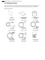
1.3 Package Content
Carefully remove the box and unpack your device. Please check if all the items listed below are
inside your package. If any of these items are missing or damaged contact us immediately.
Standard shipment list:
Panel PC
Varies by product
specifications
Quick Start Guide
(Hardcopy)
91521110102W
Driver CD & User
Manual
9171111K102L
AC Adapter
80W: 90PO12080003
Power Cable*
Varies by country
Serial Cable
94G0103090Q0
Ethernet Cable
94I0080080KF
USB Cable
9480108080Q0
VESA Screws
913511101101

13
Chapter 1: Introduction
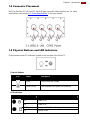
1.4 Connector Placement
IP65 Flat Stainless P-CAP Panel PC has IP65 type connectors with protection cap. For cable
specifications refer to the Ch.2,“Cable Specifications” of this user manual.
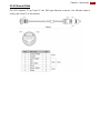
1.5 Physical Buttons and LED Indicators
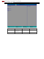
Physical buttons and LED indicators located on the rear side of the Panel PC.
Physical Buttons
Icon
Button
Description
Reset
Press to reset the system
Power On/ Off
Press to power on or power off the device
LED Indicators
LED Type
Status
Description
On
Power is on
Off
Power is off
Blinking
Storage activity (Data is being read or written)
Off
System is idle

14
IP65 Stainless P-Cap Panel PC User Manual
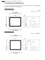
1.6 Schematics and Dimensions
This section contains mechanical drawing of the Panel PC. Notice that this is a simplified drawing
and some components are not marked in detail.
1.6.1 Dimensions 15"
Unit: mm
Dimensions : 378 x 301 x 56.4
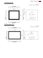
1.6.2 Dimensions 17”
Unit: mm
Dimensions : 412 x 344 x 61.3

15
Chapter 1: Introduction
1.6.3 Dimensions 19”
Unit: mm
Dimensions : 467.4 x 392 x 56.6
1.6.4 Dimensions 21.5”
Unit: mm
Dimensions : 541 x 337 x 53

16
IP65 Stainless P-Cap Panel PC User Manual
Chapter 2: Getting Started
This chapter tells you important information on power supply, adapter
and precautions tips. Pay attention to power considerations.

17
Chapter 1: Introduction
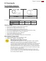
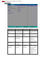
2.1 Powering On
2.1.1 AC Adapter Components
AC Adapter supplied with the power cord.
AC Adapter specifications vary by panel size.
Size
15”
19”
21.5”
AC Adapter
12V/ 80W
12V/ 80W
12V/ 80W
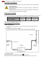
Safety Precautions:
Do not use the adapter in a high moisture environment
Never touch the adapter with wet hands or foot
Allow adequate ventilation around adapter while using
Do not cover the adapter with paper or other objects that will reduce cooling
Do not use the adapter while it is inside a carrying case
Do not use the adapter if the cord is damaged
There are NO serviceable parts inside
Replace the unit if it is damaged or exposed to excess moisture
While using the AC Adapter always:
Plug-in the power cord to easy accessible AC outlet
Plug-in the AC adapter to a grounded outlet
AC Adapter
Power Cord
Alternating Current Mise à le terre !
This product must be grounded. Use only a grounded AC outlet. Install the
additional PE ground wire if the local installation regulations require it.
*If you do not use a grounded outlet while using the device, you may notice an
electrical tingling sensation when the palms of your hands touch the device.
Ce produit doit être mis à la terre. Utiliser seulement un cordon d’alimentation
avec mise à la terre. Si les règlements locaux le requiert, installer des câbles
de mise à la terre supplémentaires.
*Si vous n’utiliser pas une prise d’alimentation avec mise à la terre, vous
pourriez remarquer une sensation de picotement électrique quand la paume
de vos mains touche à l’appareil.

18
IP65 Stainless P-Cap Panel PC User Manual
2.1.2 Power Considerations
The Panel PC operates on external DC power. Use the AC adapter included in the package.
Caution/Attention
Use only the AC adapter included in your package. Using other AC adapters may
damage the device.
Utiliser seulement le convertisseur AC inclu avec votre appareil. Utiliser d’autres
convertisseurs pourraient endommager l’appareil.
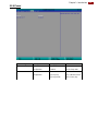
2.1.3 Power Consumption
The table below shows power consumption and AC adapter for the Flat Stainless P-CAP Panel PC.
Size
15”
19”
21.5”
Power Consumption*
52W (typ.)
56W (typ.)
66W (typ.)
*With maximum backlight and high CPU load.
2.1.4 Turning On/ Off Your Device
To turn on your device:
1. Connect the AC adapter to the DC-in jack connector located on the back side of the
Panel PC.
2. Connect the power cord to AC adapter.
3. Plug the power cord to the AC outlet and the device will turn on automatically.
To turn off your device:
To shut down your device, do the following: Tap Start ( ) > Shut down.
Wait for your Panel PC to completely turn off before disconnecting the power cord (if necessary).

19
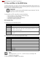
Chapter 1: Introduction
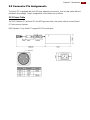
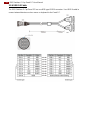
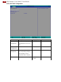
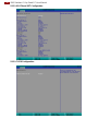
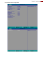
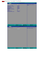
2.2 Connector Pin Assignments
This Panel PC is equipped with four M25 type waterproof connectors. Use only the cables that are
included in the package. The pin assignments of the cables are as follows.
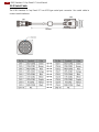
2.2.1 Power Cable
The IP65 Stainless P-Cap Panel PC has M25 type connector. Use power cable to connect Panel
PC to the source of power.
IP65 Stainless P-Cap Panel PC support 12V DC power input.

20
IP65 Stainless P-Cap Panel PC User Manual
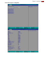
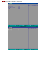
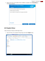
2.2.2 Serial Cable
The IP65 Stainless P-Cap Panel PC has M25 type serial port connector. Use serial cable to
connect serial interfaces.
La page est en cours de chargement...
La page est en cours de chargement...
La page est en cours de chargement...
La page est en cours de chargement...
La page est en cours de chargement...
La page est en cours de chargement...
La page est en cours de chargement...
La page est en cours de chargement...
La page est en cours de chargement...
La page est en cours de chargement...
La page est en cours de chargement...
La page est en cours de chargement...
La page est en cours de chargement...
La page est en cours de chargement...
La page est en cours de chargement...
La page est en cours de chargement...
La page est en cours de chargement...
La page est en cours de chargement...
La page est en cours de chargement...
La page est en cours de chargement...
La page est en cours de chargement...
La page est en cours de chargement...
La page est en cours de chargement...
La page est en cours de chargement...
La page est en cours de chargement...
La page est en cours de chargement...
La page est en cours de chargement...
La page est en cours de chargement...
La page est en cours de chargement...
La page est en cours de chargement...
La page est en cours de chargement...
La page est en cours de chargement...
La page est en cours de chargement...
La page est en cours de chargement...
La page est en cours de chargement...
La page est en cours de chargement...
La page est en cours de chargement...
La page est en cours de chargement...
La page est en cours de chargement...
La page est en cours de chargement...
La page est en cours de chargement...
La page est en cours de chargement...
La page est en cours de chargement...
La page est en cours de chargement...
La page est en cours de chargement...
La page est en cours de chargement...
La page est en cours de chargement...
La page est en cours de chargement...
La page est en cours de chargement...
La page est en cours de chargement...
La page est en cours de chargement...
La page est en cours de chargement...
La page est en cours de chargement...
La page est en cours de chargement...
La page est en cours de chargement...
La page est en cours de chargement...
La page est en cours de chargement...
La page est en cours de chargement...
La page est en cours de chargement...
La page est en cours de chargement...
-
 1
1
-
 2
2
-
 3
3
-
 4
4
-
 5
5
-
 6
6
-
 7
7
-
 8
8
-
 9
9
-
 10
10
-
 11
11
-
 12
12
-
 13
13
-
 14
14
-
 15
15
-
 16
16
-
 17
17
-
 18
18
-
 19
19
-
 20
20
-
 21
21
-
 22
22
-
 23
23
-
 24
24
-
 25
25
-
 26
26
-
 27
27
-
 28
28
-
 29
29
-
 30
30
-
 31
31
-
 32
32
-
 33
33
-
 34
34
-
 35
35
-
 36
36
-
 37
37
-
 38
38
-
 39
39
-
 40
40
-
 41
41
-
 42
42
-
 43
43
-
 44
44
-
 45
45
-
 46
46
-
 47
47
-
 48
48
-
 49
49
-
 50
50
-
 51
51
-
 52
52
-
 53
53
-
 54
54
-
 55
55
-
 56
56
-
 57
57
-
 58
58
-
 59
59
-
 60
60
-
 61
61
-
 62
62
-
 63
63
-
 64
64
-
 65
65
-
 66
66
-
 67
67
-
 68
68
-
 69
69
-
 70
70
-
 71
71
-
 72
72
-
 73
73
-
 74
74
-
 75
75
-
 76
76
-
 77
77
-
 78
78
-
 79
79
-
 80
80


Winmate W22IK3S-SPA3 Manuel utilisateur
- Taper
- Manuel utilisateur
- Ce manuel convient également à
dans d''autres langues
- English: Winmate W22IK3S-SPA3 User manual
Documents connexes
-
 Winmate W22IK3S-SPA3 Guide de démarrage rapide
-
 Winmate W22L100-SPA3 Guide de démarrage rapide
-
 Winmate R19L100-SPM169 Guide de démarrage rapide
-
 Winmate W22IH3S-SPA3 Guide de démarrage rapide
-
 Winmate R19IH3S-SPM169 Guide de démarrage rapide
-
 Winmate G-Win Series Guide de démarrage rapide
-
 Winmate W12IB3S-VMM9 Guide de démarrage rapide
-
 Winmate W42L100-65A3 Manuel utilisateur
-
 Winmate R15ID3S-65A1FTE Guide de démarrage rapide
-
 Winmate W24L100-GCA2 Manuel utilisateur


