Advantech VESR900 Series Guide de démarrage rapide
- Catégorie
- La mise en réseau
- Taper
- Guide de démarrage rapide

Document Number: 710-10572- 00_r2_VESR9xx_ 2118qsg
707 Dayton Road | PO Box 1040 | Ottawa, IL 61350
Phone: (815) 433-5100 | Fax: (815) 433-5109
1 (888) 948-2248 | Europe: +353 91 792444
www.advantech-bb.com | E-mail: support@advantech-bb.com
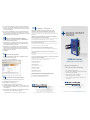
Before you begin, be
sure you have the following:
VESR900 Series
VESR9xx Ethernet Serial Server
Fast and easy on the web:
www.advantech-bb.com
QUICK START
GUIDE
+ Vlinx VESR9xx Module
+ CD with Vlinx Manager S/W and Manuals
+ This Quick Start Guide
+ Network Cable (not included)
+ Serial Cable/s (not included)
+ 10 to 48VDC (6.0W) Power Supply (not
included)
Set Up Advanced Parameters
10
1. If you want to set up Advanced parameters, click Advanced on
the Port Network Parameters page.
2. If necessary for your application, select “I want to control when
connections are forced closed, then set up the Network Watch-
dog and Serial Watchdog as required.”
3. If necessary for your application, select “I want to control data
packets are sent over the network, then set up the Character
Count, Forced Transmit, Intercharacter Timeout, Delimiters and
Delimiter Removal as required.”
4. Click Next.
Save And Log Out
11
1. If you have completed the conguration, click Save to save the
conguration to the serial server.
2. To Logout, click the Logout button.
To Test & Verify Operation
12
1. Set up serial server as a TCP Server on serial port 1.
2. Set serial port to RS-232 on serial port 1.
3. Set to 9600 8-N-1 on serial port 1.
4. Loopback serial port 1 by connecting TD to RD.
5. Open a DOS window and type “telnet x.x.x.x yyyy” where x.x.x.x
is the IP address of the serial server and yyyy is the port number
of the serial port.
6. Type characters on the keyboard. The characters should appear
in the window. If not, double check your settings.
SUITABLE FOR USE IN CLASS I, DIVISION 2, GROUPS A, B, C AND D
HAZARDOUS LOCATIONS, OR NONHAZARDOUS LOCATIONS ONLY.
CONVENANT À L’EMPLOI DANS LES SITES DANGEREUX DE CLASSE I,
DIVISION 2, GROUPES A, B, C ET D, OU DANS LES SITES NON HASARDEUX
SEULEMENT
WARNING - EXPLOSION HAZARD - SUBSTITUTION OF ANY COMPONENT
MAY IMPAIR SUITABILITY FOR CLASS I, DIVISION 2.
ATTENTION - DANGER D’EXPLOSION - LA SUBSTITUTION DE COMPOSANTS
PEUT ENTRAÎNER UNE ADÉQUATION À LA CLASSE I, DIVISION 2.
The unit is to be powered by a Class 2 power source, of a grounded-type, when
power is applied to the barrel connector.
L’unité doit être alimentée par une source d’alimentation de classe 2, de type mise à
la terre, lorsque le connecteur du canon est alimenté.
THE POWER CABLE MUST HAVE A MINIMUM RATING OF 80°C.
LE CÂBLE D’ALIMENTATION DOIT AVOIR UNE INDICATION MINIMALE DE 80
°C.
Power cannot be applied to both the terminal block and barrel connectors
simultaneously.
L’alimentation ne peut pas être appliquée simultanément aux connecteurs du bornier
et du barillet.
The use of coaxial cable for the eld wiring shall be in accordance with Class 2/Class
3 requirements in Article 725 of the NEC.
L’utilisation d’un câble coaxial pour le câblage sur site doit être conforme aux
exigences de classe 2 / classe 3 de l’article 725 du NEC.
One Conductor Per Terminal
Un conducteur par borne
Use Copper Wire Only
Utiliser uniquement du l de cuivre
Wire Size: 28 to 16 AWG
Taille de l: 28 à 16 AWG
Tightening Torque: 5 KG-CM
Couple de serrage: 5 KG-CM
Wire Temperature Rating: 105 °C Minimum (Sized for 60 °C Ampacity)
Indice de température du l: 105 °C Minimum (calibré pour 60 °C)
80 °C Maximum Surrounding Ambient Air Temperature
80 °C Température ambiante ambiante maximale
UL Class 1 / Division 2
13
5. If you want the serial server to act as a virtual communications
port for a computer, select VCOM. This allows your computer to
connect to a serial device on the network as if it were connected
to a physical COM port.
6. If you want the serial server to operate in Paired mode with an-
other serial server, select Paired, then congure it as a client or
server and set up the IP address, port numbers and other related
parameters (similar to setting up TCP).

Install the Hardware
Install Vlinx Manager Software
LED Status
1
4
2
1. Connect a 10-48 VDC (58VDC max.) power supply (6W
required).
2. Connect the network cable from the serial server to a network
drop using a standard network cable.
3. Connect the serial device(s):
• RS-232 with DB9: straight-through for DCE device, null
modem for DTE device.
• RS-232/422/485 with terminal blocks. See Appendix D in
user manual for pinouts.
UL Installation - See Step #13 for more information.
1. Insert the included CD and it should autostart.
2. Follow the prompts to install the Vlinx Manager software.
Note: Be sure you have administrative rights & disable rewalls.
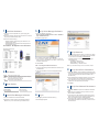
Set Up Vlinx Manager Software
5
1. Open Vlinx Manager, by clicking:
Start > Programs > B&B Electronics > Vlinx > Vlinx Man-
ager > VESR Serial Server
The Discovery page opens.
Log In
6
1. Click Login. (Password is blank from factory.)
The General page appears.
LED STATUS
Ready Blinks if system is operating correctly.
Port 1 ON indicates serial port open; blinks when data is present on serial port.
Port 2 Same as Port 1. (Present on 2-port units only.)
Link
ON indicates Ethernet operating in 100BaseTX;
Blinks when data is present on Ethernet link.
Mode Switch
3
HOLD MODE SWITCH IN for... RESULT
0 to 2 seconds Initiates a Hardware Reset.
2 to 10 seconds Enters Console Mode.
Over 10 seconds Reset to Factory Defaults.
2. To congure via the network, select Network.
3. If you know the IP address, select “The device is at this ad-
dress”, and type in the address. If not, select “I don’t know the
IP address of the device.”
4. Click Connect.
OR...Set Up the Web Interface:
1. Open a browser and type the IP address of the serial server in
the Address Bar.
2. When the serial server is found, the Conguration window
appears.
Set Up Network
7
• The serial server is set at the factory to receive an IP assign-
ment from a DHCP server. If a DHCP server is not available
on your network, it will default to 169.254.102.39.
• If this address does not work with your PC, change your
network settings to:
• IP Address = 169.254.102.1
• Subnet Mask = 255.255.255.0
• Default Gateway = 169.254.102.100
Note: If you need different settings, refer to User Manual, Chapter 4.
Set Up Serial Port Parameters
8
1. Click Port 1 Serial to open the Serial Port Parameters page.
Select the type of serial connection between the serial server
and the serial device (RS-232, RS-422, RS-485 2-wire, or
RS-485 4-wire).
2. Select the Baud Rate, Data Bits, Stop Bits, Parity and Flow
Control needed to communicate with the serial device.
3. If your serial server is 2 port, select the next port in the de-
scription box, then repeat the previous steps.
4. Click Next.
Set Up Port Network Parameters
9
1. Click Port 1 Network to open the Port Network Parameters
page.
2. Select the type of network protocol you want to use: TCP,
UDP, VCOM or Paired Mode.
3. If you select TCP, select whether the serial server will oper-
ate as a Client or Server, then congure the required IP ad-
dress, port numbers and other related parameters.
4. If you select UDP, congure the IP addresses, ports and
other related parameters for the devices you want to receive
from and send to.
-
 1
1
-
 2
2


Advantech VESR900 Series Guide de démarrage rapide
- Catégorie
- La mise en réseau
- Taper
- Guide de démarrage rapide
dans d''autres langues
Documents connexes
Autres documents
-
MicroNet SP3350A Manuel utilisateur
-
-
Extron WAP 100AC Manuel utilisateur
-
Tripp Lite SNMPWEBCARD Le manuel du propriétaire
-
-
-
Yamaha CS-700 Mode d'emploi
-
ATEN PE6208AV Manuel utilisateur
-
EchoStar HUGHES inmarsat 9502 Manuel utilisateur