Osburn OP00025 Guide d'installation
- Catégorie
- Poêles
- Taper
- Guide d'installation

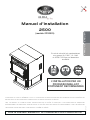
Installation Manual
2500
(OP00025 model)
Printed in Canada
Safety tested according to ULC S627,
UL 1482 and ASTM E1509 by an
accredited laboratory.
INSTALLATION BY A
PROFESSIONAL IS STRONGLY
RECOMMENDED
CONTACT LOCAL BUILDING OR FIRE OFFICIALS ABOUT RESTRICTIONS AND INSTALLATION INSPECTION REQUIREMENTS IN
LOCAL AREA.
READ THIS ENTIRE MANUAL BEFORE INSTALLATION AND USE OF THIS PELLET STOVE. FAILURE TO FOLLOW THESE
INSTRUCTIONS COULD RESULT IN PROPERTY DAMAGE, BODILY INJURY OR EVEN DEATH.
READ AND KEEP THIS MANUAL FOR REFERENCE
ENGLISHFRANÇAIS
45910_IA
2022-01-24

Page 2 Installation Manual - 2500
ENGLISH
RECOMMENDATIONS
It is highly recommended that this appliance be installed and serviced by professionals who are
certified in the United States by NFI (National Fireplace Institute® ) or in Canada by WETT (Wood
Energy Technology Transfer) or in Quebec by APC (Association des Professionnels du Chauffage).
If this appliance is not properly installed, combustible materials near it may overheat and
catch fire. To reduce the risk of fire, follow the installation instructions in this manual exactly. Contact
local building or fire officials about restrictions and installation inspection requirements in local area. It
is also recommended to inform your home insurance company.
It may be needed to get a building permit for the installation of this appliance and the venting system
that it is connected to.
Read this entire manual before installing this stove.
GENERAL INFORMATION
This stove does not work with a natural draft or without power source to activate the blowers
and the pellet feeding system. The stove will not work in the event of a power outage.
This stove has been developed and built to be used as a residential heater. Commercial or industrial
use is prohibited and will void the warranty.
The information given on the certification label affixed to the appliance always overrides the information
published, in any other media (owner’s manual, catalogues, flyers, magazines or web sites).
Mixing of appliance components from different sources or modifying components is prohibited and
will void the warranty.
Any modification to the stove that has not been approved in writing by the testing authority is prohibited
and violates CSA B365 (Canada), and ANSI NFPA 211 (USA).
Stove Builder International inc. (SBI) grants no warranty, implied or stated, for the poor installation or
lack of maintenance of this appliance and assumes no responsibility of any consequential damages.
When locating this appliance, make sure the venting system will not interfere with any truss, roof
beams, wall studs, water pipes or electrical wiring. It may be easier to relocate the appliance than to
rework the building structure.
This stove is certified to comply with EPA NSPS 2015 particulate emission standards and is not
approved for sale after May 15th 2020.


Page 4 Installation Manual - 2500
ENGLISH
TABLE OF CONTENTS
Recommendations ....................................................................................................................... 2
General Information ...................................................................................................................... 2
Available Options and Accessories ............................................................................................. 3
Specifications ............................................................................................................................... 5
Performances ............................................................................................................................... 6
Dimensions ................................................................................................................................... 6
Appliance Installation ................................................................................................................... 7
Safety Information .................................................................................................................. 7
Regulations ............................................................................................................................ 7
Appliance Set Up ................................................................................................................... 8
Clearances to Combustibles ..................................................................................................10
Floor Protection.....................................................................................................................11
Venting System ........................................................................................................................... 12
General Information ...............................................................................................................12
Safety Information .................................................................................................................12
Regulations ...........................................................................................................................12
Equivalent Vent Length (EVL) ..................................................................................................13
Termination Location .................................................................................................................. 14
Canada .................................................................................................................................14
United States ........................................................................................................................15
Direct Vent System ................................................................................................................15
Canada ...................................................................................................................................15
United States ...........................................................................................................................15
Venting System Installation Configuration ................................................................................ 16
Through the Wall ..................................................................................................................16
Through the Roof ..................................................................................................................17
Through a Factory Built Chimney ............................................................................................18
Through a Masonry Chimney ..................................................................................................19
Mobile and manufactured Home ............................................................................................... 20
Thermostat Installation .............................................................................................................. 21
Location ...............................................................................................................................21
Electrical Connection .............................................................................................................22
Fresh Air Intake .......................................................................................................................... 23
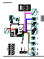
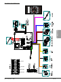
Wiring Diagram ........................................................................................................................... 25
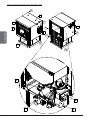
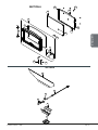
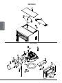
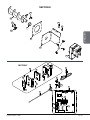
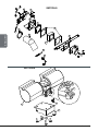
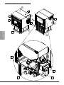
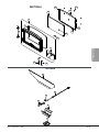
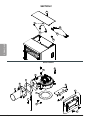
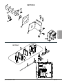
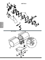
Exploded Views and Parts List .................................................................................................. 26

Page 5Installation Manual - 2500
ENGLISH
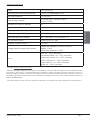
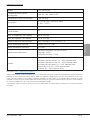
SPECIFICATIONS
Model 2500 (OP00025)
Recommended venting pipe diameter 3 in. or 4 in. depending on EVL1.
Flue outlet diameter 3 in. (80 mm)
Pellet venting standard ULC/ORD-C441, CAN/ULC S609
UL 641 (TYPE L)
Approved for alcove installation Yes
Approved for mobile home installation2Yes
Shipping weight (without option) 286 lb (130 kg)
Appliance weight (without option) 253 lb (115 kg)
Particulate emission standard EPA / CSA B415.1-10, ASTM E2779
USA standard (safety) ASTM E1509, UL 1482
Canadian standard (safety) ULC S627
Average electrical power consumption3
Voltage and Frequency 120VAC et 60 Hz
Ingition : 2.60A
Continuous operation : 2.50A
Fuses
Main: 8A - 250V slow blow
Convection blower: 5A - 250V slow blow
Combustion blower: 5A - 250V slow blow
Exhaust blower: 5A - 250V slow blow
Auger motor #1: 3A - 250V slow blow
Igniter: 8A - 250V slow blow
1 See section « Venting - Equivalent Vent Length ».
2 Mobile home (Canada) or manufactured home (USA): The US Department of Housing and Urban Development describes “manufactured homes”
better known as “mobile homes” as followed; buildings built on xed wheels and those transported on temporary wheels/axles and set on a
permanent foundation. In Canada, a mobile home is a dwelling for which the manufacture and assembly of each component is completed or
substantially completed prior to being moved to a site for installation on a foundation and connection to service facilities and which conforms to the
CAN/CSA-Z240 MH standard.
3 Unless stated otherwise, measures were taken directly at the main power source and include all electrical components present in the appliance

Page 6 Installation Manual - 2500
ENGLISH
PERFORMANCES
Values are as measured per test method. Results may vary depending on pellet quality, density, length, and
diameter.
Fuel type Wood Pellet (Premium grade or better)1
Maximum heat input rate239,260 BTU/h (11.5 kW)
Overall heat output rate (min. to max.)36,648 BTU/h to 28,540 BTU/h (1.95 kW to 8.36 kW)
Average overall efficiency370.3 % (HHV)475.8 % (LHV)5
Optimum efficiency678.4 %
Burn rate 1.2 lb/h to 4.7 lb/h (0.54 kg/h to 2.14 kg/h)
Average particulate emissions rate70.96 g/h (EPA / CSA B415.1-10)
Average CO87.6 g/h
1 Grades of pellet fuel are determined by organizations such as Pellet Fuels Institute (PFI), ENplus and CANplus.
2 Based on the maximum burn-rate and a dry energy value of pellet at 8,600 BTU/lb.
3 As measured per CSA B415.1-10 stack loss method.
4 Higher Heating Value of the fuel.
5 Lower Heating Value of the fuel.
6 Optimum overall efciency at a specic burn rate (LHV).
7 This appliance is ofcially tested and certied by an independent agency
8 Carbon monoxide.
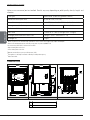
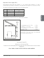
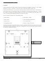
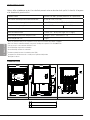
DIMENSIONS
2
5
7
/
8
"
656mm
9 1/2"
240mm
17 1/4"
438mm
21 1/8"
5
3
7
m
m
23 3/8"
595mm 24 3/8"
620mm
23 1/4"
591mm
9"
228mm 17 7/8"
454mm 33"
8
3
9
m
m
A
B
27 5/8"
7
0
3
m
m
10 5/8"
2
6
8
m
m
5 1/4"
134mm
O3"
76mm
O
3"
76mm
B
A
Front view Side view Back view
A
B
FRESH AIR INLET
FLUE OUTLET

Page 7Installation Manual - 2500
ENGLISH
APPLIANCE INSTALLATION
Safety Information
• If this stove is not properly installed, a house fire or smoke spillage may result. To reduce the risks,
follow the installation instructions.
• Do not use makeshift materials or make any compromises when installing this appliance.
• This stove is mobile home approved and in these cases requires installation of a fresh air kit,
sold separately. The stove must be attached to the structure of the mobile home and the structural
integrity of the mobile home floor, wall, and ceiling / roof must be maintained. Do not install in a
sleeping room of a mobile home.
• This stove must be connected to a standard 120V / 60Hz, grounded electrical outlet. Do not use
an outlet adapter, an extension cord or sever the grounding plug. Do not route the electrical
cord underneath, in front or over the stove.
• This stove is not recommended to be installed in a bedroom.
• Burning any solid fuels generates carbon monoxide in low concentration. This gas is evacuated
by the exhaust venting system. In higher concentrations, carbon monoxide is toxic and may
cause death. To prevent this, ensure that the exhaust venting system is airtight and installed
properly.
• A smoke detector, a carbon monoxide detector and a fire extinguisher should be installed in the
house. The location of the fire extinguisher should be known by all family members.
This product can expose you to chemicals including carbon monoxide, which is
known to the State of California to cause cancer, birth defects or other reproductive
harm. For more information go to www.P65warnings.ca.gov/
Regulations
• When installed and operated as described in these instructions, this pellet stove is suitable for use
as a freestanding heater in residential installations.
• In Canada, the CSA B365 Installation Code for Solid Fuel Burning Appliances and Equipment and
the CSA C22.1 Canadian National Electrical Code are to be followed in the absence of local code
requirements.
• In the USA, the ANSI NFPA 211 Standard for Chimneys, Fireplaces, Vents and Solid Fuel-Burning
Appliances and the ANSI NFPA 70 National Electrical Code are to be followed in the absence of
local code requirements.
• This stove must be connected to a pellet venting system complying with the requirements for Pellet
Vent UL 103, UL 641, ULC S629M, CAN/ULC S609 and ULC/ORD C441 standards or to a code-
approved masonry chimney with a stainless steel flue liner.

Page 8 Installation Manual - 2500
ENGLISH
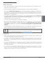
Appliance Set Up
• Read and follow appliance and venting manufacturer’s instructions;
• Remove appliance and accessories from packaging. Make sure no parts are missing or damaged;
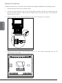
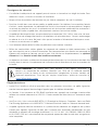
• Level the stove using threaded legs, located under the stove;
Threaded legs location
• Make sure the fresh air intake back draft shutter opens and closes freely;
Back draft shutter location
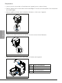
• Remove tools and other accessories inside the stove;
1
2
3
4
No Tools / Accessories
1Baffle
2Warning sheet
3Humidity absorbant
4Owner’s manual
Tools and accessories located inside the stove

Page 9Installation Manual - 2500
ENGLISH
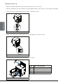
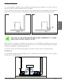
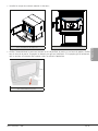
• Install baffle as shown below
Baffle installation direction
Baffle final location in the stove
• Test the door seal by closing and latching the door on a strip of paper. Test all around the door.
The paper should not slip out easily. If it does, see the «adjusting the door» section in the operation
manual.
Door sealing test

Page 10 Installation Manual - 2500
ENGLISH
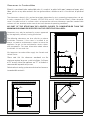
Clearances to Combustibles
Material is considered to be combustible when it is made of, or plated with wood, compressed paper, plant
fibers, plastics or any other materials that can ignite and burn, whether or not it is fire resistant, or plastered
or not.
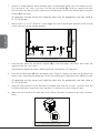
The clearances shown in this section have been determined by tests according to procedures set out
in safety standards ULC S627 (Canada), ASTM E1509 and UL 1482 (United States). When the pellet
stove is installed so that its surfaces are at, or beyond the minimum clearances specified, combustible
surfaces will not overheat under normal and even abnormal operating conditions.
NO PART OF THE STOVE MAY BE LOCATED CLOSER TO COMBUSTIBLES THAN THE
MINIMUM CLEARANCES SPECIFIED ON THE CERTIFICATION LABEL.
Clearances may only be reduced by means approved
by the regulatory authority having juridisction.
The following clearances are also valid for an alcove
installation. However, if the stove is installed in an
alcove, to perform maintenance, expect to move the
appliance to get to the maintenance access doors
and components. For more information about alcove
installation visit our web site.
All clearances to combustibles apply for Canada and
United States.
Please note that the clearances mentioned are the
mimimum required to ensure a safe installation. A distance
of 24" on each side of the appliance and 12" at the back is
recommended to provide easy access.
Refer to exhaust venting system manufacturer for clearances
to combustible materials.
6"
152mm
3"
76mm
3"
76mm
Side clearance Corner clearance
3"
76mm
48"
1219mm
Back and ceiling clearance

Page 11Installation Manual - 2500
ENGLISH
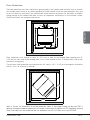
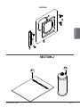
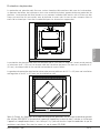
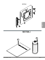
Floor Protection
The floor protection must be a continuous (grouted joints) non combustible material such as ceramic
tile, cement board, brick, or any other approved or listed material suited for floor protection. Any type
of tile will require a continuous non combustible sheet beneath to prevent the possibility of embers
falling through to the combustible floor if cracks or separation should occur in the finished surface.
Check local codes for approved alternatives.
6"
152mm 6"
152mm
6"
152mm
29"
737mm
29 1/2"
749mm
2"
51mm
2"
51mm
Rectangular floor protection
Floor protection must extend at least 6" (152 mm) in front of the loading door opening and 6"
(152 mm) on each side of the loading door. It must also extend at least 2" beyond each side of any
horizontal venting pipe.
The minimum floor protection area required for this stove is 29 ½" x 29" for a rectangular installation
and 40" x 40" for a corner installation.
40"
1016mm
40"
1016mm
Corner floor protection
Note: In Canada, the dimensions of the floor protection shown in the previous image can be used ONLY if
opening the appliance door or removing the ash drawer is done when the appliance is OFF completely, meaning
there is no more fire in the combustion pot and the blowers are off. In all other cases, see CSA B365.

Page 12 Installation Manual - 2500
ENGLISH
VENTING SYSTEM
General Information
Even though the chimney draft is mechanical, a suitable venting system will ensure a natural draft
which will prevent smoke spillage in the home if a power outage occurs. Moreover, a suitable venting
system configuration will help getting the best efficiency out of the stove when installed in accordance
with the required equivalent vent length (EVL).
This stove is equipped with a blower that draws air for combustion. The venting system restricts the
blower’s ability to move the amount of air required for proper combustion. An overly restrictive venting
system will cause incomplete combustion problems, more frequent cleaning and poor performance.
It is recommended to select a location for the appliance that will provide a venting system with the
shortest possible equivalent vent length (EVL).
The installation configurations in the following sections are for informative purposes only. Always refer
to the vent manufacturer’s instructions for installation.
Safety Information
Connect this stove only to a listed pellet exhaust venting system for use with solid fuel or to a lined
chimney conforming to national and local building codes.
DO NOT CONNECT THIS STOVE TO ANY OTHER EXISTING VENTING SYSTEM SERVING
ANOTHER APPLIANCE.
The venting system must be completely airtight and properly installed. All vent connector joints
must be sealed and fastened in accordance with the pellet venting manufacturer’s installation
instructions to ensure consistent performance and avoid smoke and ash spillage.
DO NOT INSTALL A FLUE DAMPER IN THE VENTING SYSTEM OF THIS UNIT.
DO NOT CONNECT TO OR USE IN CONJUNCTION WITH ANY AIR DISTRIBUTION
DUCTWORK.
The venting system should be checked, at least twice a year for any buildup of soot or creosote.
Regulations
In Canada, it is recommended to use a listed pellet vent that meets the CAN/ULC S609 or
ULC/ORD C441 Standard. A chimney listed to ULC S629M is also suitable for installation with this
stove.
For the United States, it is recommended to use a listed pellet vent that meets the UL 641 Standard.
A chimney listed to UL 103 is also suitable for installation with this stove.
This stove can be vented in an existing factory-built or masonry chimney with the addition of a stainless
steel liner. The liner should be listed and should meet the ULC S635 CAN/ULC S640 standard in
Canada and the UL 1777 standard in the USA. Refer to the instructions provided by the venting
system manufacturer, especially when passing through a wall, ceiling or roof.

Page 13Installation Manual - 2500
ENGLISH
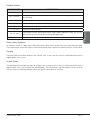
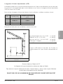
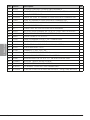
Equivalent Vent Length (EVL)
Recommended venting pipe inner diameter is 3" for a ground floor installation. A 4" pipe is
recommended for basement installation or if the equivalent vent length (EVL) is more than 15 feet.
To calculate the Equivalent Vent Length, refer to the following table:
Qty Type of pipe Equivalent Vent Lenght
(EVL)
190° Elbow or T 5 feet
145° Elbow 3 feet
1 feet Horizontal Pipe 1 feet
1 feet Vertical Pipe ½ feet
Example of how to calculate the EVL for a ground floor installation:
2 ft. of horizontal run (2 X 1' EVL) = 2' EVL
90° elbow or T (1 X 5' EVL) = 5' EVL
12 ft. of vertical run (12 X 0.5' EVL) = 6' EVL
Termination / Cap = 0' EVL
Total EVL = 13' EVL
Since the EVL is less than 15 feet, the venting pipe
inner diameter recommanded is 3".
Diagram to calculate the Equivalent Vent Length
Never exceed 30 feet of EVL.
Horizontal runs shall not exceed 9 feet.
To reduce the risk of smoke spillage there should always be at least one foot of vertical rise for each foot of
horizontal run.
AT ALL TIMES, AT LEAST 3 FEET OF VERTICAL RISE IS NEEDED.

Page 14 Installation Manual - 2500
ENGLISH
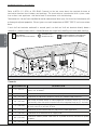
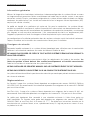
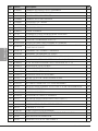
TERMINATION LOCATION
Refer to NFPA 211 (USA) or CSA B365 (Canada) to find out more about the required distance of
termination location from windows and openings. The termination of a mechanical draft system, other
than a direct vent appliance, shall be located in accordance with the following:
Termination of a side wall vent should be located to avoid personal burn injury, fire hazard and interference with
or damage to adjacent properties. Exhaust gases can reach temperatures of 500°F (260°C) and cause serious
burns.
A vent shall not terminate underneath a veranda, porch, or deck and shall not terminate directly above a
sidewalk or a paved driveway which is located between two single family dwelling and serves both dwellings.
v
A
A
J
B
B
B
B
L
BB
B
I
A
A
K
F
VENT TERMINAL
SORTIE DU TUYAU D’EVACUATION
VAIR SUPPLY INLET
ENTRÉE D’AIR FRAIS
AAREA WHERE TERMINAL IS NOT PERMITTED
ZONE OU LA SORTIE N’EST PAS PERMISE
V
V
V
V
V
V
V
V
H
F
Premitted termination location
Canada
CLEARANCES DESCRIPTION
A12" (30 cm) Clearances above grade level or any adjacent surface that might support
snow, ice, or debris.
B39" (100 cm) Clearance to window or door that may be opened.
F39" (100 cm) Clearance to corner or adjacent wall or any combustible materials.
H39" (100 cm) Not to be installed above a meter/regulator assembly within 39" (100 cm)
horizontally from the vertical center-line of the regulator and for 15' vertically.
I72" (183 cm) Clearance to gas service regulator vent outlet or within 39" (100 cm) of an
oil tank vent or an oil tank fill inlet.
J39" (100 cm) Clearance to the combustion air inlet to any other appliance.
K72" (183 cm) Clearance to a mechanical air supply inlet.
L84" (213 cm) Clearance above paved side-walk or a paved driveway located on public
property.
39" (100 cm) Clearance to property boundary.

Page 15Installation Manual - 2500
ENGLISH
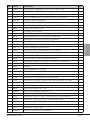
United States
CLEARANCES DESCRIPTION
36" (91 cm) Clearance above any forced air inlet located within 120" (305 cm).
48" (122 cm) Clearance below and horizontally from any door, window or gravity air inlet into
any building.
12" (30 cm) Clearance above any door, window or gravity air inlet into any building.
24" (61 cm) Clearance from an adjacent building.
84" (213 cm) Clearance above grade when located adjacent to a public walkway.
12" (30 cm) Clearance above grade.
36" (91 cm) Termination cannot be located above a gas meter/regulator within 36" (91cm)
horizontally of the vertical center line of the regulator.
72" (183 cm) Clearance of a gas service regulator vent outlet.
Direct Vent System
An exhaust system is called direct when the exhaust and the air intake are made using the same pipe.
The internal pipe serves for exhaust while the external pipe supplies the combustion air to the stove.
Canada
The permitted termination locations for a direct vent system are the same as those permitted with a
regular pellet vent system.
United States
The permitted termination location for a direct vent system are the same as those permitted with a
regular pellet vent system except for the following : The termination shall be located not less than 9"
(23 cm) from any opening through which vent gases could enter a building.

Page 16 Installation Manual - 2500
ENGLISH
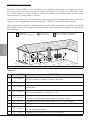
VENTING SYSTEM INSTALLATION CONFIGURATION
Burning solid fuels generates carbon monoxide in low concentration. In higher
concentrations, carbon monoxide is toxic and may cause death. To prevent this,
the exhaust venting system must be airtight. All vent connector joints must be
sealed and fastened in accordance with the pellet venting manufacturer’s installation
instructions.
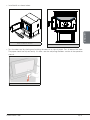
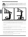
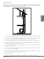
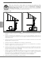
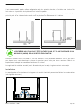
Through the Wall
12
3
4
56
3
1
4
2
3
5
56
Sol
Ground
Ground installation Basement installation
1. Position appliance following appliance and venting system manufacturer’s installation instructions.
2. Install a stove connector (1) or tee on the appliance flue collar. Seal with high temperature silicone.
If necessary, use an additional horizontal length between the flue collar and the tee.
3. Locate the position of the pipe in the wall and cut a hole in the wall the appropriate size for the
wall thimble.
4. Install the wall thimble (2) according to the vent manufacturer’s instructions.
5. Connect enough sections to protrude the horizontal pipe from the outside wall. Install a tee (3) on
the pipe that runs through the wall.
6. Install a vertical pipe section that is at least 36" long. Refer to vent manufacturer’s instructions for
clearances to combustible materials (exterior wall) and use of wall supports (4).
7. Install a 90 degree elbow (5) facing out from the wall, and then attach a stainless steel vent cap
(6), facing towards the ground (a 45 degree elbow or a horizontal vent cap may be used). A spark
arrester must be attached to the vent cap.
The installation of a spark arrester on the termination of the vent is mandatory.
8. Seal the exterior wall bracket with silicone.
DANGER

Page 17Installation Manual - 2500
ENGLISH
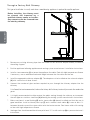
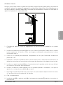
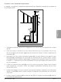
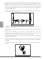
Through the Roof
Where vent pipes pass through an attic, a closet or any confined space, a floor or ceiling, only approved
venting components shall be used. To pass through a combustible wall or partition, the installation must meet
CSA-B365 standard for solid fuel-burning appliances and equipment.
1
2
3
4
5
6
7
Through the roof installation
1. Position appliance following appliance and venting system manufacturer’s installation instructions.
2. Install a stove connector (1) or tee on the appliance flue collar. Seal with high temperature silicone.
If necessary, use an additional horizontal length between the flue collar and the tee.
3. Use a plumb bob to determine where the exhaust pipe will pass through the ceiling and roof.
4. Cut a hole in the ceiling and in the roof and frame the rough opening. Refer to the vent manufacturer’s
instructions for dimensions and construction rules.
5. Install a ceiling support (2) in the rough opening and the first vent section following vent
manufacturer’s instructions.
6. Install a firestop radiation shield (3) on any subsequent ceiling/floor, except for the attic where an
attic insulation shield is required (4).
7. Run the necessary section of vent vertically so the rain cap exceeds the highest point of the roof
at least 24" in United States and at least 36" in Canada.
8. Install roof support.
9. Install roof flashing (5), storm collar (6) and rain cap (7) as per manufacturer’s instructions.

Page 18 Installation Manual - 2500
ENGLISH
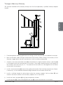
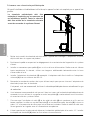
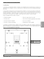
Through a Factory Built Chimney
This type of installation is usually used when a wood burning appliance is replaced by a pellet appliance.
Before installing, the chimney must
be cleaned and inspected by a
qualified chimney sweep or installer.
Any creosote must be removed from
the existing chimney.
1
2
4
5
6
7
8
9
3
Through a factory built chimney installation
1. Remove any existing chimney pipe from the heater to the universal adapter already installed in
the ceiling support.
2. Position appliance following appliance and venting system manufacturer’s installation instructions.
3. Install a stove connector (1) or tee on the appliance flue collar. Seal with high temperature silicone.
If necessary, use an additional horizontal length between the flue collar and the tee.
4. Install the appropriate chimney adapter (2). The adapter must be installed on the universal adapter
(3) with a minimum of three screws.
5. Connect the number of pipe sections required to pass through the chimney adapter into the
chimney.
It is allowed, but not recommended, to leave the factory built chimney to naturally evacuate the combustion
gases.
6. It is highly recommended to either extend the pellet venting through the chimney or to connect
the vent pipe to a stainless steel liner (4) following the venting system manufacturer’s instructions.
7. Make sure there is a roof flashing (5) and a storm collar (6) already installed and that they are in
good condition. Install a chimney end cap (7) and a second storm collar (8). Leave at least ½»
between the end cap and the storm collar to let the heat evacuate. Seal storm collar with venting
or liner with high temperature silicone.
8. Venting or liner should exceed the chimney of at least 12". Install a rain cap (9) as per manufacturer’s
instructions.

Page 19Installation Manual - 2500
ENGLISH
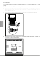
Through a Masonry Chimney
The structural condition of the masonry chimney must first be inspected by a qualified chimney sweep or
installer.
5
1
2
3
7
8
4
6
Through a Masonry Chimney
1. Position appliance following appliance and venting system manufacturer’s installation instructions.
2. Mark the location where the pipe should enter the masonry. Make a hole in the masonry of the
diameter suggested by the vent manufacturer. Install a masonry adapter (1).
3. Connect a tee with a removable snout (2) to the bottom of a rigid or flexible stainless steel liner (3)
in accordance with the manufacturer’s instructions. Liner lengh should be equal to the length of
the chimney from the mark plus 12". The center of the tee snout must be aligned with the center
of the hole in the masonry.
4. Install a stove connector (4) or tee on the appliance flue collar. Seal with high temperature silicone.
If necessary, use an additional horizontal length between the flue collar and the tee.
5. Install a sufficient length of vertical pipe to join the masonry adapter. Add an elbow (5) and
connect the vertical section to the masonry adapter with a slip section.
6. Install and seal a top plate (6) with high temperature silicone.
7. Install top plate (6), storm collar (7) and rain cap (8) as per manufacturer’s instructions

Page 20 Installation Manual - 2500
ENGLISH
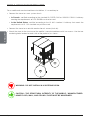
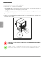
MOBILE AND MANUFACTURED HOME
For a mobile and manufactured home installation, it is mandatory to
• Connect the stove to a vent system who is:
• In Canada : certified according to the standard ULC/ORD-C441 or CAN/ULC-S609. A chimney
meeting the requirements of ULC S629M can also be used.
• In the United States, certified according to the UL 641 standard. A chimney that meets the
requirements of UL 103 standard may also be used.
• Connect the stove to an outside combustion air source (fresh air).
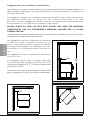
• Attach the stove to the structure of the mobile / manufactured home with two screws. Use the two
anchoring holes located on each side of the pedestal, as shown .
Anchoring holes location
WARNING : DO NOT INSTALL IN A SLEEPING ROOM.
CAUTION : THE STRUCTURAL INTEGRITY OF THE MOBILE / MANUFACTURED
HOME FLOOR, WALL, AND CEILING / ROOF MUST BE MAINTAINED.
La page est en cours de chargement...
La page est en cours de chargement...
La page est en cours de chargement...
La page est en cours de chargement...
La page est en cours de chargement...
La page est en cours de chargement...
La page est en cours de chargement...
La page est en cours de chargement...
La page est en cours de chargement...
La page est en cours de chargement...
La page est en cours de chargement...
La page est en cours de chargement...
La page est en cours de chargement...
La page est en cours de chargement...
La page est en cours de chargement...
La page est en cours de chargement...
La page est en cours de chargement...
La page est en cours de chargement...
La page est en cours de chargement...
La page est en cours de chargement...
La page est en cours de chargement...
La page est en cours de chargement...
La page est en cours de chargement...
La page est en cours de chargement...
La page est en cours de chargement...
La page est en cours de chargement...
La page est en cours de chargement...
La page est en cours de chargement...
La page est en cours de chargement...
La page est en cours de chargement...
La page est en cours de chargement...
La page est en cours de chargement...
La page est en cours de chargement...
La page est en cours de chargement...
La page est en cours de chargement...
La page est en cours de chargement...
La page est en cours de chargement...
La page est en cours de chargement...
La page est en cours de chargement...
La page est en cours de chargement...
La page est en cours de chargement...
La page est en cours de chargement...
La page est en cours de chargement...
La page est en cours de chargement...
La page est en cours de chargement...
La page est en cours de chargement...
La page est en cours de chargement...
La page est en cours de chargement...
La page est en cours de chargement...
La page est en cours de chargement...
La page est en cours de chargement...
La page est en cours de chargement...
-
 1
1
-
 2
2
-
 3
3
-
 4
4
-
 5
5
-
 6
6
-
 7
7
-
 8
8
-
 9
9
-
 10
10
-
 11
11
-
 12
12
-
 13
13
-
 14
14
-
 15
15
-
 16
16
-
 17
17
-
 18
18
-
 19
19
-
 20
20
-
 21
21
-
 22
22
-
 23
23
-
 24
24
-
 25
25
-
 26
26
-
 27
27
-
 28
28
-
 29
29
-
 30
30
-
 31
31
-
 32
32
-
 33
33
-
 34
34
-
 35
35
-
 36
36
-
 37
37
-
 38
38
-
 39
39
-
 40
40
-
 41
41
-
 42
42
-
 43
43
-
 44
44
-
 45
45
-
 46
46
-
 47
47
-
 48
48
-
 49
49
-
 50
50
-
 51
51
-
 52
52
-
 53
53
-
 54
54
-
 55
55
-
 56
56
-
 57
57
-
 58
58
-
 59
59
-
 60
60
-
 61
61
-
 62
62
-
 63
63
-
 64
64
-
 65
65
-
 66
66
-
 67
67
-
 68
68
-
 69
69
-
 70
70
-
 71
71
-
 72
72


Osburn OP00025 Guide d'installation
- Catégorie
- Poêles
- Taper
- Guide d'installation
dans d''autres langues
- English: Osburn OP00025 Installation guide
Autres documents
-
Drolet ECO-55 ST PELLET STOVE Guide d'installation
-
-
-
-
US Stove Company 5040 Le manuel du propriétaire
-
Ashley Hearth Products APC4000M Manuel utilisateur
-
 Cleveland PS20W Manuel utilisateur
-
USSC VG60 Mode d'emploi
-
