
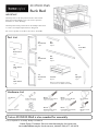
Hardware List
Part List
Home Styles Customer Service: www.homestyles-furniture.com,
888-680-7460, 877-831-0319
Tool(s) required for assembly: Phillips screwdriver
IMPORTANT
Carefully remove all the parts from the carton and
place them individually on a soft cloth to prevent
scratches or other damage.
Carefully and strictly follow these assembly instructions
to ensure a completed product as designed.
Do not use power tools above 8 volts to assemble.
20 05530 0565
Bunk Bed
Small Hex Wrench
1 pc.
Hex Wrench
1 pc.
Carton 20 05530 0564 is also needed for assembly.
S2.
Back Panel
1 pc.
S3.
Back Panel
1 pc.
S5.
Back Panel
1 pc.
T1.
Stair Panel
1 pc.
T2.
Stair Panel
1 pc.
T3.
Stair Panel
4 pcs.
U2.
Rail
2 pcs.
V.
Stair Rail
1 pc.
W.
Upright
1 pc.
Refer to later page(s) of these
instructions for drawer assembly.
X.
Drawer
4 pcs.
U1.
Rail
2 pcs.
Cam Lock Screw
32 pcs. (+1 extra)
Cam Lock
32 pcs. (+4 extra)
M4x1”
Machine Screw
4 pcs.
Knob (22mm)
4 pcs.
M6x30
Head Cap Bolt (short)
21 pcs. (+1 extra)
M6x55
Head Cap Bolt (medium)
1 pcs. (+1 extra)
M6x25
Wood Screw for Drawer
32 pcs. (+1 extra)
M6x45
Head Cap Bolt for Bed
3 pcs. (+1 extra)

Assembly Instructions 2/10
IMPORTANT
Use a soft cloth between these parts and the floor.
Do not use power tools above 8 volts to assemble.
Do not tighten all the bolts until each part is properly assembled.
The unit must be level to work properly. Use the included adjustable levelers to level.
Keep Hex Wrench as the bolts may need to be tightened in the future.
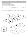
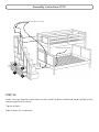
STEP 11
Insert Cam Lock Screws into pre-drilled holes in Stairs (M1), (M2), (M3), (M4), (M5), Base (N),
Side Panel (O) and Risers (P2), (P3), then tighten. (See Figure 6)
Follow instructions in carton 20 05530 0563 first, then proceed with Step 11.
Figure 6
M4
M3
M1
M5
M2
Cam Lock Screw
N
P2
P3
O
Cam Lock Screw

Assembly Instructions 3/10
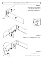
STEP 12
Attach Base (N) to Side Panel (O)
with Cam Locks. (See Figure 7)
Note: A Philips screwdriver 5” or
less in length is recommended.
O
N
Figure 7
Cam Lock
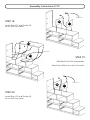
STEP 13
Attach Rail (U1) and Middle Panel (R) to unit.
STEP 14
Attach Rail (U1) to unit.
Attach Riser (P2) to unit with Cam Locks.
U1
R
Cam Lock
P2
U1

Assembly Instructions 4/10
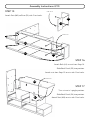
STEP 15
Attach Stair (M5) to Riser (P3) with Cam Locks.
Cam Lock
Cam Lock
S4
M4
STEP 17
Turn unit to its’ upright position.
Slide Back Panel (S4) into position.
Attach Stair (M4) to unit with Cam Locks.
Cam Lock
STEP 16
Attach Rails (U2) to unit from Step 14.
Slide Back Panel (S5) into position.
Attach unit from Step 15 to unit with Cam Locks.
P3
M5
U2
U2
S5

Assembly Instructions 5/10
Cam Lock
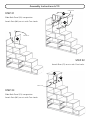
STEP 18
Attach Riser (P1) and Divider (Q)
to unit with Cam Locks.
P1
Q
STEP 19
Slide Back Panel (S3) into position.
Attach Stair (M3) to unit with Cam Locks.
Cam Lock
M3
S3
STEP 20
Attach Riser (P1) and Divider (Q)
to unit with Cam Locks.
P1
Q
Cam Lock

Assembly Instructions 6/10
M2
S2
Cam Lock
STEP 21
Slide Back Panel (S2) into position.
Attach Stair (M2) to unit with Cam Locks.
STEP 22
Attach Riser (P1) to unit with Cam Locks.
P1
Cam Lock
STEP 23
Slide Back Panel (S1) into position.
Attach Stair (M1) to unit with Cam Locks.
S1
Cam Lock
M1

Assembly Instructions 7/10
W
T3
T3
T3
T3
V
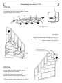
STEP 24
Assemble Stair Panels (T3), Stair Rail (V)
and Upright (W) with Head Cap Bolts (short),
tightening bolts only halfway.
Head Cap Bolt (short)
Figure 8
STEP 25
Attach unit from Step 24 and Stair Panel (T2)
to unit from Step 23 with Head Cap Bolts (short),
tightening bolts only halfway.
Head Cap Bolt (short)
T2
Head Cap Bolt (short)
Head Cap Bolt (medium)
STEP 26
Attach Head Cap Bolt (medium) to unit,
tightening bolt only halfway.
Attach Stair Panel (T1) to unit with
Head Cap Bolts (short), tightening bolts
only halfway.
Tighten all bolts used in Steps 24, 25 and 26.
T1

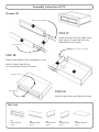
Part List
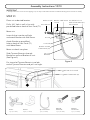
STEP 29
Attach Knob (22mm) with Machine Screw.
X1.
Drawer Front
4 pcs.
X2.
Drawer Back
4 pcs.
X3.
Drawer Side
4 pcs.
X4.
Drawer Side
4 pcs.
X5.
Drawer Bottom
4 pcs.
Machine Screw
STEP 28
Slide Drawer Bottom (X5) into grooves in unit.
Attach Drawer Side (X4) to
unit with Wood Screws for Drawer.
Assembly Instructions 8/10
Knob (22mm)
Drawer (X)
Roller at back
X2
X3
Wood Screw for Drawer
X1
STEP 27
Attach Drawer Front (X1) and Drawer
Back (X2) to Drawer Side (X3) with
Wood Screws for Drawer.
X4
X5
Wood Screw for Drawer

STEP 30
Attach unit from Step 24 to bunk bed unit with Head Cap Bolts for Bed and Head Cap Bolt (short),
tightening bolts only halfway.
Tighten all bolts.
Slide Drawers (X) into position.
Assembly Instructions 9/10
Head Cap Bolt for Bed
Head Cap Bolt (short)
X
X
X
X

Assembly Instructions 10/10
STEP 31
Place unit at desired location.
Drill a 3/8” hole in wall in-line with
pre-drilled hole on back of Stair Panel (T1).
Move unit.
Insert Anchor into the wall hole
and attach Bracket with Wall Screw.
Attach Bracket at pre-drilled
hole on back of Stair Panel (T1)
with Wood Screw.
Move unit back into place.
Slide Tip-over Restraint through
Bracket on wall and Bracket on unit.
(See Figure 9)
Put tie end of Tip-over Restraint into lock
end of Tip-over Restraint and pull until tight.
IMPORTANT
To help reduce the risk of the unit tipping over, the Tip-over Restraint must be installed following these instructions exactly.
Figure 9
Wood Screw
Wall Screw
Bracket
on wall
Anchor in wall
3/8” wall hole
Pre-drilled hole on
back of Stair Panel (T1)
Tie end
Lock end
Bracket on back
of Stair Panel (T1)
Tip-over
Restraint
Anchor
1 pc. (+1 extra)
Bracket
2 pcs. (+1 extra)
Tip-over Restraint
1 pc. (+1 extra)
M3.5x38
Wall Screw
1 pc. (+1 extra)
M3.5x16
Wood Screw
1 pc. (+1 extra)
Drill 3/8” hole in wall
Back of Stair Panel (T1)
T1

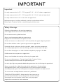
IMPORTANT
Use only mattress which is 74” – 75” long and 37 1/2" – 38 1/2" wide on upper bunk.
Use only mattress which is 74” – 75” long and 52 1/2“– 53 1/2" wide on lower bunk.
Use only mattress which is 10” or less thick on upper bunk.
Replacement parts, including additional guardrails may be obtained from
Home Styles Customer Service at www.homestyles-furniture.com.
Important
Follow the information on the warnings appearing
on the upper bunk end structure and on the carton.
Do not remove warning label from bed.
Always use the recommended size mattresses to
help prevent the likelihood of entrapment or falls.
Surface of mattress must be at least 5” (127 mm) below the upper edge of guardrails.
Do not allow children under 6 years of age to use the upper bunk.
Periodically check and ensure that the guardrail, ladder, and other components
are in their proper position, free from damage, and that all connectors are tight.
Do not allow horseplay on or under the bed and prohibit jumping on the bed.
Prohibit more than one person on upper bunk.
Always use the ladder for entering and leaving the upper bunk.
Do not use substitute parts. Contact Home Styles Customer Service
at www.homestyles-furniture.com for replacement parts.
Use of a night light may provide added safety precaution for a child using the upper bunk.
Always use guardrails on both long sides of the upper bunk. If the bunk bed
will be placed next to a wall, the guardrail that runs the full length of the bed
should be placed against the wall to prevent entrapment between the bed and wall.
The use of water or sleep flotation mattresses is prohibited.
STRANGULATION HAZARD – Never attach or hang items to any
part of the bunk bed that are not designed for use with the bed;
for example, but not limited to, hooks, belts, and jump ropes.
Keep these instructions for future reference.
Safety Warnings

IMPORTANTES
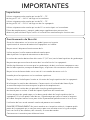
Importantes
Utilisez uniquement des matelas qui est de 74" – 75"
de long et 37 1/2" – 38 1/2" de large sur la couchette.
Utilisez uniquement des matelas qui est de 74" – 75"
de long et 52 1/2“ – 53 1/2" de large sur des lits superposés.
Utilisez uniquement des matelas qui est de 10" ou moins épais sur la couchette.
Pièces de remplacement, y compris garde-corps supplémentaires peuvent être
obtenus à partir de Home Styles service à la clientèle au www.homestyles-furniture.com.
Avertissements de Sécurité
Suivez les informations sur les mises en garde figurant sur la partie
supérieure de la structure d'extrémité et superposés sur la boîte.
Ne pas retirer l'étiquette d'avertissement du lit.
Utilisez toujours la taille recommandée du matelas pour
aider à prévenir le risque de coincement ou de chutes.
La surface du matelas doivent être d'au moins 5" (127 mm) sous le bord supérieur du garde-corps.
Ne permettez pas aux enfants de moins de 6 ans d'utiliser les lits superposés.
Vérifier régulièrement et s'assurer que les garde-corps, de bain, et d'autres composants sont
dans la bonne position, exempts de dommages, et que tous les connecteurs sont bien serrés.
Ne pas laisser les bousculades sur ou sous le lit et interdire de sauter sur le lit.
Interdire plus d'une personne sur la couchette supérieure.
Toujours utiliser l'échelle pour l'entrée et à la sortie de l'angle supérieur des lits superposés.
N'utilisez pas les articles de substitution. Contact service à la clientèle de Home Styles
au www.homestyles-furniture.com pour les pièces de remplacement.
Utilisation d'une lumière de nuit peut offrir une plus grande précaution
de sécurité pour un enfant à l'aide de la partie supérieure de la couchette.
Utilisez toujours des garde-corps sur les deux grands côtés de l'angle supérieur des lits
superposés. Si le lit est placé à côté du mur, le garde-corps qui court sur toute la longueur
du lit doit être placé contre le mur pour éviter la provocation policière entre le lit et le mur.
L'utilisation de l'eau ou de sommeil matelas de portance est interdite.
DANGER D'ÉTRANGLEMENT- Ne jamais attacher ou s'accrocher articles à n'importe quelle
partie du lit superposé qui ne sont pas conçus pour une utilisation avec le lit; par exemple,
mais non limité à, des crochets, des ceintures, et sauter des cordes.
Conservez ces instructions pour référence future.

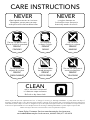
NEVER
use glass cleaners on
finished furniture. Ammonia
chemically attacks the finish.
allow liquids to remain on furniture.
Absorption causes parts to warp
and split and finishes to delaminate.
NEVER
CARE INSTRUCTIONS
Do not use rubber
based placemats.
PREVENT
DISCOLORING
Do not use commercial
waxes and polishes.
PREVENT
YELLOWING
Do not place hot
objects on surface.
PREVENT
FINISH DAMAGE
Do not write
directly on surface.
PREVENT
MARKING
Do not use power tools
above 8 volts to assemble.
PREVENT
CRACKING
Do not place
in direct sunlight.
PREVENT
FADING
with a soft cloth moistened
in lukewarm soap and water.
Buff with a dry clean cloth.
CLEAN
Home Styles will provide replacements free of charge for missing or damaged hardware or parts within 30 days of
purchase. Digital images of the defective parts may be required. If the product was not purchased from an authorized
retail affiliate, Home Styles is under no obligation to provide replacement parts. Parts are not available for fully assembled
items nor are parts available for sale. Replacements for missing or damaged hardware or parts may be requested at:
www.homestyles-furniture.com/customer-service/replacement-parts
Home Styles Customer Service: www.homestyles-furniture.com,
888-680-7460, 877-831-0319
-
 1
1
-
 2
2
-
 3
3
-
 4
4
-
 5
5
-
 6
6
-
 7
7
-
 8
8
-
 9
9
-
 10
10
-
 11
11
-
 12
12
-
 13
13


Home Styles 5530-56D Assembly Instructions
- Taper
- Assembly Instructions
- Ce manuel convient également à
dans d''autres langues
- English: Home Styles 5530-56D
Documents connexes
Autres documents
-
Home Decorators Collection OME-66002 Guide d'installation
-
 Flair Furnishings Oscar Triple Le manuel du propriétaire
-
 Dorel Home Furnishings FA7499W Mode d'emploi
-
Dorel Living 0-65857-17755-8 Mode d'emploi
-
-
-
Dorel Living DL1008TFBB-1 Manuel utilisateur

