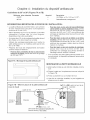
Thermador PRG366EPG/01 Guide d'installation
- Catégorie
- Fours
- Taper
- Guide d'installation
Ce manuel convient également à

For Thermador ProfessionaP PRO-GRAN DTM
Gas Ranges
Pour toutes cuisinieres a gaz Thermador Professional ®
PRO-GRAND TM
A= _>J=,=ic==3=, =..
ModeLs
PG30
PG36
PG48

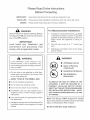
Please Read Entire Instructions
Before Proceeding
mMPORTANT:
mNSTALLER:
OWNER:
Save these instructions for the Local Gas Inspector's use.
Please leave these Installation Instructions with this unit for the owner.
Please retain these instructions for future reference.
Disconnect power before installing. Before
turning power ON, be sure that all controls
are in the OFF position.
IMPORTANT
LocaJ codes vary. Installation, gas
connections and grounding must
comply with all applicable codes.
For Massachusetts Instamaations:
,
.
3.
Installation must be performed by a qualified
or licensed contractor, plumber or gas fitter
qualified or licensed by the state, province or
region where this appliance is being in-
stalled.
Shut-off valve must be a "T" handle gas
cock.
Flexible gas connector must not be longer
than 36 inches.
If the information in this manual is not
followed exactly, a fire or explosion may
result causing property damage, personal
injury or death.
m Do not store or use gasoline or other flam-
mable vapors and liquids in the vicinity of this
or any other appliance.
WHAT TO DO _F YOU SMELL GAS
[] Do not try to light any appliance.
[] Do not touch any electrical switch.
[] Do not use any phone in your building.
[] Immediately call your gas supplier from a
neighbor's phone. Follow the gas supplier's
instructions.
[] If you cannot reach your gas supplier, call the
fire department.
Installation and service must be performed by
a qualified installer, service agency or the gas
supplier.
,_ WARNtNG
m All Ranges can tip
m Injury to Persons
could result
m lnstaHAnti-Tip Device
m See _nstaHation
Instructions
TO REDUCE THE RiSK OF TIPPING OF THE
APPMANCE, IT MUST BE SECURED BY A
PROPERLY INSTALU=D ANTI-TIP DEVICE.
VERIFY THAT TH_=ANTi-TIP D_=WC_=IS _=NGAG _=D
PER INSTALLATION INSTRUCTIONS. (NOTE:
ANTi-TIP DEVICE IS REQUIRED ON ALL 30" AND
36" RANGES)
Note: This Range is NOT designed for installa-
tion in manufactured (mobile) homes orfor instal-
lation in Recreational Park Trailers.
Do Not install this range outdoors.

Contents
Important Installation Information ................. 1
Step 1: Ventilation Requirements ................ 2
Step 2: Cabinet Preparation ................. 3 - 7
Step 3: Unpacking, Moving
and Placing the Range ......................... 8 - 9
Step 4: Installing AntioTip Device ...... 10 - 11
Step 5: Gas Requirements and Hookup .... 12
Step 6: Electrical Requirements,
Connection and Grounding ....................... 13
Step 7: Backguard Installation .................. 14
Step 8: Door Removal and Installation ...... 15
Step 9: Burner Test and Adjustment.. 16 - 17
Installer Checklist ...................................... 18
To Clean and Protect Exterior Surfaces .... 18

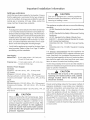
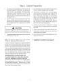
Important Installation Information
GAS type verification
Verify the type of gas supplied to the location. Ensure
that the appliance is connected to the type of gas for
which it is certified. All ranges are certified for use with
natural gas or propane (LP) gas. Make certain the
range matches the gas type available.
Important
* A backguard must be utilized when there is less than
a 12" horizontal clearance between combustible ma-
terials and the backedge of the range. The Thermador
Low Back backguard must be ordered separately and
installed at the rear of the range. For island installa-
tions and other installations with more than 12" clear-
ance, an optional stainless steel Island Trim is avail-
able to cover the backguard mounting flanges.
. Verify that the appliance is correct for the type of gas
being provided. Refer to Step 5 on Page 12 before
proceeding with the installation.
Gas Supply:
Natural Gas - 6 inch water column. (14.9 mb) min,
14 inch (34.9 rob) max.
Propane Gas - 11 inch water column. (27.4 mb), min,
14 inch (34.9 rob) max.
Electric Power Supply:
30" Model:
4 Burners - 120 VAC, 60 Hz, IPh. 15Amp circuit.
36" Models:
6 Burners- 120 VAC, 60 Hz., IPh, 15Amp circuit.
4 Burners with Grill- 120VAC, 60 Hz, 1Ph, 15Amp circuit.
4 Burners with Griddle- 120 VAC, 60 Hz, IPh, 20 Amp
circuit.
48" Models:
6 Burners with Grill- 120VAC, 60 Hz, 1Ph. 15Amp circuit.
6 Burners with Griddle- 120 VAC, 60 Hz. IPh. 20 Amp
circuit.
4 Burnerswith Grill and Griddle- 120 VAC, 60 Hz, 1Ph, 20
Amp circuit.
CAUTION
When connecting the unit to propane gas, make
certain the propane gas tank is equipped with its
own high-pressure regulator in addition to the
pressure regulator supplied with the range. The
maximum gas pressure to this appliance
must not exceed 14.0 inches water column
(34.9 rob) from the propane gas tank to the
pressure regulator.
CAUTION
This unit is designed as a cooking appliance.
Based on safety considerations, never use itfor
warming or heating a room.
This appliance complies with one or more of the following
standards:
UL 858, Standard for the Safety of Household Electric
Ranges
UL 923, Standard for the Safety of Microwave Cooking
Appliances
• UL 507, Standard for the Safety of Electric Fans
ANSi Z21.1, American National Standard for House-
hold Cooking Gas Appliances
CANiCSA-C22.2 No. 113-M1984 Fans and Ventila-
tors
CAN/CSA-C22.2 No. 61-M89 Household Cooking
Ranges
It is strong_ recommended that this appliance be
installed in conjunction with a suitable overhead vent
hood. (See Step 1 for Ventilation Requirements.) Due
to the high heat capability of this unit, particular atten-
tion should be paid to the hood and duct work instal-
lation to assure it meets local building codes.
It is the responsibility of the owner and the installer to
determine if additional requirements and!or standards
apply to specific installations.
CAUTION
To eliminate risk of burns or fire caused by
reaching over heated surface units, cabinet
storage located above the surface units
should be avoided.
Check local building codes for the proper method of
appliance installation. Local codes vary. Installation,
electrical connections and grounding must comply
with all applicable codes. In the absence of local
codes the appliance should be installed in accor-
dance with the National Fuel Gas Code ANSI Z223.1/
NFPA 54 current issue and National Electrical Code
ANSI/NFPA 70-current issue. In Canada, installation
must be in accordance with the CAN 1-B149.1 and .2
-Installation Codes for Gas Burning Appliances and/
or local codes.

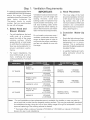
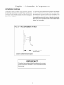
Step 1
It is stron IgLv_recommended that a
suitable exhaust hood be installed
above the range. Downdraft
ventilation should notbe used. The
table below indicates the
Thermador hoods, by model
number, that are recommended
for use with all ranges.
1. Select Hood and
B ower Modems:
Forwall installations, the hood
width must, at a minimum,
equal the width of the range
cooking surface. Where
space permits, a hood larger
in width than the cooking sur-
face may be desirable for im-
proved ventilation perfor-
mance.
For island installations, the
hood width should, at a mini-
mum, overhang the range
cooking surface by 3" on each
side.
Ventilation Requirements
2.
Ventilation hoods and blowers are
designed for use with single wall
ducting. However, some local
building codes or inspectors may
require double wall ducting. Con-
suit local building codes and/or
local agencies before starting to
assure that hood and duct instal-
lation will meet local requirements.
Do not install a microwave oven /
ventilator combination above the
range, as these types of units do
not provide the proper ventilation
and are not suitable for use with
the range.
3_
Hood Placement:
The lower edge of the hood
should be installed a minimum
of 36" above the range cook-
ing surface. Also use a 36"
minimum clearance if the hood
contains any combustible
materials such as a wood cov-
ering. (See Figure 1).
Consider Make-Up
Air:
Due to the high volume of ven-
tilation air, a source of outside
replacement air is recom-
mended. This is particularly
important for tightly sealed and
insulated homes.
A qualified heating and venti-
lating contractor should be
consulted.
30" RANGE
36" RANGE
48" RANGE
PH30CS VTRI030D,
PHE30 / 36 VTR1530D,
orVTN1030C
HNW36YS VTRI030D,
orVTRI530D
PH36CS/42CS
PHE36 / 42
HNW36YS / 42YS
PH48CS / 54CS
PHE48 / 60
VTRI030D,
VTR1530D,
orVTNI030C
VTRI030D,
orVTRI530D
VTRI030D,
VTR1530D,
orVTNI030C
HNW48YS VTR 1030D,
or VTR1530D
HNI42YS VTRI030D
HTNI42YS orVTR1530D
HNI42YS VTRI030D
HTNI42YS orVTR1530D
HNI48YS / 54YS
HTNN8YS/54YS
VTR1530D
Notes: * For wall installations where adequate space is available, the installer or user may elect to
use a hood that is wider than the rangetop cooking surface. This may be particularly beneficial
for installations having a long duct run or when heavy usage of the grill is anticipated, in which
improved capturing of the cooking exhaust is desired.
•* Thermador offers a choice of remote (VTRI03OD or VTR1530D) or internal (VTN1030C)
blowers for use in wall installations.

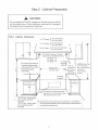
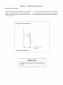
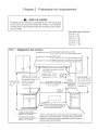
Step 2: Cabinet Preparation
.
.
The range is a free standing unit. If the unit is to
be placed adjacent to cabinets, the clearances
shown in Fig. 1 are required. The same clear-
ances apply to island installations, except for the
overhead cabinets, which must have a space
wide enough to accept the flared island hood as
indicated in Fig. 1.
The 36" ranges may be recessed into the cabk
nets beyond the edge of the front face of the oven
(See Figures 2A and 2B). The 30" and 48" ranges
are not approved to be installed flush with the
cabinets.
CAUTION
In these installations, the door and cabinet on
36-inch models can cause a pinching hazard.
3. The gas and electrical supply should be within the
zones shown in Fig. 3A.
.
5.
.
.
.
Any openings in the wall behind the range and in
the floor under the range must be sealed.
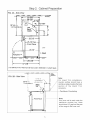
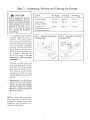
When there is less than a 12" horizontal clear-
ance between combustible material A and the
back edge of the range above the cooking sur-
face, a Thermador Low Back or Pot and Pan
Shelf must be installed. (See Fig. 2A). When
clearance to combustible material A is over 12",
a Thermador Island Trim may be used. (See Fig.
2B). Figures 2A and 2B indicate the space re-
quired for each type of backguard.
A three (3) inch minimum clearance is needed
when the range is installed beside a combustible
side wall.
Always keep appliance area clear and free from
combustible materials, gasoline and other flam-
mable vapors and liquids.
Do not obstruct the flow of combustion and ven-
tilation air to the unit.
Note: The maximum depth of over head cabinets
installed on either side of the hood is 13".
A 36-inch minimum clearance is required between
the top of the range and the bottom of an unprotected
cabinet. It is recommended that the bottom of the
wood or metal cabinet be protected by not less than
1,1'4inch of aflame retardant material covered with not
less than No. 28 MSG sheet steel, 0.015 inch (0.38
mm) thick stainless steel, 0.024 inch (0.6 mm) alumk
num, or 0.020 inch (0.5 mm) thick copper. Flame
retardant materials bear the following mark:
UNDERWRITERS LABORATORIES INC.
CLASSIFIED MINERAL AND FIBER BOARDS
SURFACE BURNING CHARACTERISTICS
Followed by the flame spread and smoke ratings,
these designations are shown as "FHC (Flame
Spread/Smoke Developed)." Materials with "O" flame
spread ratings are flame retardant. Local codes may
allow other flame spread ratings.
A As defined in the "National Fuel Gas Code"
(ANSI Z223.1 / NFPA 54, Current Edition).

Step 2: Cabinet Preparation
CAUTION:
Do not install the 30" and 48" ranges such that the oven door isflush
with the cabinet face. A flush installation could result in damage to
the cabinets due to exposure to high heat.
FIG. 1 Cabinet Clearances
m
O0
18"
Min.
36"minimumfrombottomof
OverheadHoodtocooking
surface(also36"rain.ifhood
containscombustible
materialsA )
°°I
'35o7/8" iV]in,Range Height
with Leveling Legs fully
retracted
"36-3/4" Max. Range Height
with Leveling Legs fully
extended,
For 30" Ranges _ 30"or36"WideHood
36" or42" for Island
f
36"or42"Wide Hood
For 36" Ranges _.
42" or48"for Island
\
For 48" Ranges { 48", 54", or 60" Wide Hood
48" or54" for Istand
Cooking
Surface
For Electrical and Gas Supply Zone,
m
0
CAUTION: See Figs.
3" Min. to 2A, and 2B. 36"
combustible Min. to combustible
(_side watt_ material A,
materialA , I from cooking
(both sides) I surface
1
i
see Figure 3A. Zone size and position ,_
differ according to the model.
\
A as defined in the"National Fuet Gas Code" (ANSI Z223.1, Current Edition).
*The range height is adjustable. The level ofthe range top must beat the same
eve orabovethe countertop eve.

Step 2: Cabinet Preparation
F{G. 2A - Side View
/i'll / /// ////. /1// //// -- Combustible
_ 32-5/8'"
M_ials &
I _ 29-1/2" ,,
I Potan d _,,,]2-7/&"
Pan _ I
36"MIn. to ! Sh_tf "-4._ -I
Combustibles A I LOW L._
'_---- 26-3/8"
/
_25-112" max./
./Front Face
29-112"--
//// I
,[_----28-3/8" -----_-
47-3/8" 71
I
I
I
I
/
/
!
I
[o
Kickplate
///I
3/8"
-'-Wall
////
A as defined in the "National Fuel Gas Code" (ANSI Z223.1, Current Issue).
FiG. 2B - Side View t
I
t
36" MIn._to
Combustibles A
I
t
t
t
t
12" Min. to
Combustibles A
with Island Trim
Island
/ Front Face
L J,
Note:
For Island Trim installations,
counter surface should have a
cantilever edge meeting the back
section of the Island Trim
accessory,
Countertop
Note:
If an inner wall is used under the
cantilever counter top, there
should be a 1/8" gap from the rear
of the range to the inner wall,

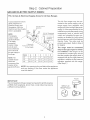
Step 2: Cabinet Preparation
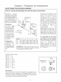
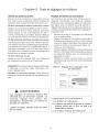
GAS AND ELECTRIC SUPPLY ZONES:
F_G. 3A Gas & E_ectrica_ Supply Zones for AH Gas Ranges
Typical placement shown.
Other placement of
Electrical Supply and
Receptacle within the
Electrical and Gas Supply
Zone is acceptable.
NOTE:
If not already
present, install
gas shut-offvalve
in an easiJy
accessible
location. Make
sure all users
knowwhere and
how to shut off
the gas supply to
the range.
NOTE: The
installershould
inform the
consumer of the
location of the
gasshutzoffvalve.
3/4" Ftex Line to
Appliance
1/2"
NPT 120 VAC Receptacle
(Shown) or Junction
I Box
I .... Centerline of
Electrical
I
2" Maximum
Protrusion from Wait "_
_ a
for Gas Supply
Floor
Model A B C D E
30" 8" 12" 10" 6-1/2" 5ol/4"
36" 10ol/2" 15" 10ol/2" 6ol/2" 5ol/4"
48" 16-1/2" 16" 15-1/2" 6ol/2" 5ol/4"
The All Gas ranges may be con-
nected to the power supply with a
range supply cord (supplied with
range) or by hard-wiring to the power
supply. It is the responsibility of the
installer to provide the proper wiring
components (cord or conduit and
wires) and complete the gas con-
nection as dictated by local codes
and ordinances, and/or the National
Electric Code. The units must be
properly grounded. Refer to Step 6
for details.
The range must be connected
only to the type of gas for which
it is certified. If the range is to be
connected to propane gas, ensure
that the propane gas supply tank is
equipped with its own high pressure
regulator in addition to the pressure
regulator supplied with the range.
(See Step 5.)
NOTE:Any opening in the wall behind the appliance
and any opening in the floor under the appliance
must be sealed.
mMPORTANT:
The cord supplied with gas ranges having electric griddle requires
a NEMA 5-20 receptacle, shown here. Local codes may require
a different wiring method.
NEMA 5z20
RECEPTACLE
PLUG

Step 2 Cabinet Preparation
ELECTRICAL SUPPLY
Installation of the range must be planned so that the
rough-in of the junction box for the receptacle or
conduit connection will allow maximum clearance to
the rear of the unit.
To minimize binding when the unit is connected to
the receptacle or junction box, orient the receptacle
or conduit connector, and slide back into position.
F_G. 3B Wall Connection
I -1/4" Max. When
' . Plugged in
Power Cord & Receptacle
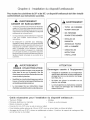
IMPORTANT
For all gas range models with an electric griddle, a
dedicated 20 Amp service is required for proper
operation.

Step 3 Unpacking, Moving and Placing the Range
CAUTION
Proper equipment and ad-
equate manpower must be
used in moving the range to
avoid injury, and to avoid
damage to the unit or the
floor. The unit is heavy
and shouJd be handled
accordingJy.
The range has an approximate
shipping weight as shown in
Chart A. The grates, griddle
plate and frame, burner caps,
front kick panel and oven racks
must be removed to facilitate
handling. This will reduce the
weight as shown in ChartA and
allow the range to pass through
30" doorways. See Figs. 2A
and 2B on Page 5. Do not
remove the grill or griddle
assemblies.
Remove the outer carton and
packing material from the ship-
ping base. The all gas ranges
are held to the skid by four (4)
bolts (see Fig. 4 and 5). After
removing the bolts the range
must be lifted and removed from
the skid.
mMPORTANT: Do not lift the
range by the oven door's
handJe, as this may damage
the door hinges and cause
the door to fit incorrectJy to
the oven cavity.
Cha_ A 30" Range 36" Range 48" Range
Shipping Weight 335 Jbs. 444 Ibs. 584 Jbs.
Weight without 285 Ibs. 390 Ibs. 524 Ibs.
packing materials
Without door(s),
burner caps, front kick
panel and oven racks
215 Ibs. 295 Ibs. 395 Ibs.
FIG. 4 - Removat of Two Front
Shipping BoJts
FiG. 5 - RernovaJ of Two Rear
Shipping BoJts
Left Rear ,if'Y"
Shipping
Bolt
!
NOTE: Leave adhesive-backed
foam layer over brushed-metal
surfaces to protect finish from
scratches, until the range is in-
stalled in final position.

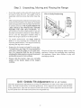
Step 3: Unpacking, Moving and Placing the Range
Due to the weight, a dolly with soft wheels should
be used to move this unit. The weight must be
supported uniformly across the bottom (See Fig.
6).
After transporting the professional range by dolly
close to its final location, the range can be tipped
back and supported on the rear legs while the dolly
is carefully removed. THE FLOOR UNDER THE
LEGS SHOULD BE PROTECTED BEFORE
PUSHING THE UNiT mNTO POSlTmON. The
anti-tip device must be installed (Step 4), gas and
electrical connections should be made (Steps 5
and 6), and the backguard installed (Step 7)
before the range is placed in its final position.
For proper performance, the range must be
_eveL (It is very important for all products that
have the griddle feature.) The range is leveled by
adjusting the legs with a wrench.
Replace the kick panel and install the oven door.
To install door, see Page 15. Do not install the
oven door until the range is in its final loca-
tion. ff is important that the two (2) screws
retaining the kick pane_ are secure to prevent
accidenta_ access to hot surfaces.
Ensure that the burner caps are correctly
seated on the burner bases of the range's
cooktop.
Range
Musl be
Uniformly
Supported
by Braces
Provided
on Bottom
Range
22-3t4"
Remove all tape and packaging before using the
appliance. Destroy the packaging after unpacking
the appliance. Never allow children to play with
packaging material.
Grill / Griddle Tilt Adjustment (Notonallmodels)
Check the griddle frame adjustment by pouring two tablespoons of water on the back of the griddle
plate. The water should slowly roll into the grease tray. If not, adjust the two screws under the back
of the griddle frame. Start with one half turn CCW of the screws. Further adjustment should be made
by one=quarter turn until water slowly flows into the grease tray.

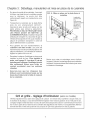
Step 4: Installing Anti-Tip Device
For aH 30" and 36" ranges, an anti-tip device must be installed as per these
instructions.
_, WARNING
RANGE TtPPING HAZARD
AH ranges can tip and injury can result.
To prevent accidental tipping of the range,
attach it to the floor, wall or cabinet by
installing the Anti-Tip Device supplied.
A risk of tip-over may exist if the appmi-
ance is not installed in accordance with
these instructions.
mfthe range is pulled away from the wall
for c_eaning, service or any other reason,
ensure that the Anti-Tip Device is prop-
er_y reengaged when the range is pushed
back against the wall. mnthe event of
abnorma_ usage (such as a person stand-
ing, sitting, or _eaning on an open door},
failure to take this precaution can result
in tipping of the range. Persona_ injury
might result from spilled hot _iquids or
from the range itself.
_, WARNING
o ALL RANGES CAN
T_P
o _NJURY TO PER-
SONS COULD RE-
SULT
o _NSTALL ANT_-T_P
DEVICES PACKED
W_TH RANGE
o SEE _NSTALLAT_ON
_NSTRUCT_ONS
WARNtNG
ELECTRICAL SHOCK HAZARD
. Use extreme caution when drilling ho_es
into the wall or floor. There may be con-
cealed electrica_ wires _ocated behind the
wall or under the floor.
. mdentify the e_ectricaL circuits that could
be affected by the installation of the Anti-
Tip Device, then turn off power to these
c ircu its.
. Failure to follow these instructions may
result in e_ectrica_ shock or other per-
sona_ injury.
ATTENTION
PROPERTY DAMAGE
. Contact a qualified installer or contrac-
tor to determine the proper method for
drilling ho_es through the wall or floor
materia_ (such as ceramic the, hardwood,
etc.}
. Do not s_ide the range across an unpro_
tected floor.
. Failure to follow these instructions may
result in damage to wall or floor cover-
ings.
Too_s Needed for Installation of Anti-Tip Device:
•Screwdriver, Phillips •Hammer
• Drill, electric or hand • Pencil or other marker
• Measuring tape or ruler
• 1/8" drill bit (wood or metal wall or floor)
•3/16" carbide:tipped masonry drill bit (concrete or concrete block wall or floor)
• 3/16" anchors, drywall or concrete, 4 each (not required if mounting bracket is being attached to solid wood or metal)
10

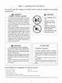
Step 4 Installing Anti -Tip Device
30" and 36" Ranges (Figures 7A and 7B)
Thermador Service Pa_ No. Qty
415078 4
487310 1
Description
Screw, Phillips, #10 x 1-1/2"
Anti-Tip Bracket, Floor-Mounted
_MPORTANT _NSTALLAT_ON _NFORMAT_ON:
• The anti-tip bracket may be attached to a solid
wood cabinet having a minimum wall thickness of
3/4".
• The thickness of the wall or floor may require use
of longer screws, available at your local hardware
store.
• In aJlcases, at least two (2) of the bracket mount-
ing screws must be fastened to solid wood or
metal.
• Use appropriate anchors when fastening the
mounting bracket to any material other than hard-
wood or metal.
• Prepare holes at fastener locations as identified
below:
For walls, wall studs, or floors composed of
F_G. 7A - Mounting Anti-tip Bracket
o e !
o oJ
solid wood or metal, drill 1/8" pilot holes.
For walls or floors composed of drywall,
sheet-rock or other soft materials, drill 3/16"
holes to a minimum depth of 1-3/4", then tap
plastic anchors into each of the holes using
a hammer.
For walls or floors composed of concrete or
concrete block, drill 3/16" holes to a mini-
mum depth of 1-3/4", then tap concrete
anchors into each of the holes using a
hammer.
For walls orfloors having ceramic tile cover-
_, drill 3/16" holes through the tile only, then
drill into the material behind the tile as indi-
cated immediately above.
If the range is moved to a new location, the Anti-
Tip Device must be removed and reinstalled.
MOUNTING ANT_-T_P BRACKET
The alternative floor mounted bracket shall be installed
as follows:
a) Place bracket on floor in position shown in Figure
7B.
b) Secure to floor or wall stud.
c) Later, when the unit is installed, the adjustable leg
will slide under the bracket.
F_G. 7B
- Placement of Anti-tip Bracket (Top View)
Wall Line
Cabinet
Floor
./ /
\--
Front (typical-
Right Cabinet I ether s de)
:_m 2oi/2, _ from edge of range
\
11

Step 5:
Verify the type of gas being used at the installation site.
As shipped from the factory, units are configured
for use with only natural gas or propane (LP) gas.
Make certain the range matches the type of gas
available at this location. These ranges are NOT
convertible between different types of gas.
For installation of the appliance at high altitude, please
consult your local gas company for their recommen-
dation of the correct orifice sizes and any other
necessary adjustments that will provide proper gas
combustion at specified altitudes.
CAUTION
When connecting unit to propane gas, make
certain the propane gas tank is equipped with its
own high pressure regulator in addition to the
pressure regulator supplied with the appliance.
The pressure of the gas supplied to the appli-
ance regulator must not exceed 14"
(34.9 mb) water column.
Supply Pressure:
Manifold Pressure:
Natural Gas Requirements:
Inlet Connection: 3/4" NPT external
1/2" NPT internal
(Minimum 3/4" dia. flex line.)
6" min. to 14" max. water column.
(14.9 to 34.9 mb)
5" water column (12.5 mb)
Supply Pressure:
Manifold Pressure:
Propane Gas Requirements:
Inlet Connection: 3/4" NPT external
1/2" NPT internal
(Minimum 3,14'' dia. flex line.)
11" min. to 14" max. water column.
(27.4 mb to 34.9 mb)
10" water column (24.9 mb)
WARNING
Gas Requirements and Hookup
HOOK UP
• A manual gas shut-off valve must be installed
external to the appliance, in a location accessible
from the front, for the purpose of shutting off the
gas supply. The supply line must not interfere with
the back of the unit. Make sure the gas supply is
turned off at the manual shut-off valve before
connecting the appliance.
• The range is supplied with its own pressure regu-
lator that has been permanently mounted within
the range body.
Use 3/4" flex line to connect between the gas
supply and the appliance inlet pipe, which exits the
upper rear of the appliance. The appliance pipe
connection has a 3/4" NPT external thread and a
1/2" NPT internal thread. (See Photo A.) Use
caution to avoid crimping the 3/4" flex line when
making bends.
• The gas supply connections shall be made by a
competent technician and in accordance with
local codes or ordinances. In the absence of a
local code, the installation must conform to the
National Fuel Gas Code ANSI Z223.1iNFPA54-
current issue.
Always use pipe sealing compound or Teflon®
tape on the pipe threads, and be careful not to
apply excessive pressure when tightening the
fittings.
• Leak testing of the appliance shall be in accor-
dance with the following instructions.
• Turn on gas and check supply line connections
for beaks using a soap and water solution,
Bubbles forming indicate a gas leak. Repair all
beaks immediately after finding them.
• Do not use a flame of any kind to check for
gas leaks.
Photo A
Gas line must not come in contact with any
components inside back cover of range. Run
gas line in channel in back of range.
Use 3/4" flex line to connect between the gas supply
and the appliance manifold pipe, which exits the
upper left rear of the appliance.
12

Step 6: Electrical Requirements, Connection & Grounding
Before installing, turn power OFF at the service
panel. Lock service panel to prevent power from
being turned ON accidentally.
Chart B: Electrica_ Suppmy Circuit Requirements
MODEL TYPE VOLTAGE CURRENTRATING FREQUENCY PHASE
30" 120 VAC 15 Amps 60 Hz. Single
36" 120 VAC 15 Amps 60 Hz. Single
36" with Grill 120VAC 15 Amps 60 Hz. Single
36" with Griddle 120 VAC 20 Amps 60 Hz. Single
48" with Grill 120VAC 15 Amps 60 Hz. Single
48" with Griddle 120 VAC 20 Amps 60 Hz. Single
48" with Grill 120 VAC 20 Amps 60 Hz. Single
and Griddle
A neutral supply wire must be provided from the
power source (breaker/fuse panel) because criti-
cal range components, including the surface
burner spark re-ignition modules, require 120
VAC to operate safely and properly. An improper
120 VAC power supply will cause malfunction,
damage to this appliance, and possibly create a
condition of shock hazard. If the correct power
supply circuit is not provided, it is the responsibil-
ity and obligation of the installer and user to have
proper power supply connected. This must be
accomplished in accordance with all applicable
local codes and ordinances by a qualified electri-
cian. In the absence of local codes and ordi-
nances, the power supply connection shall be in
accordance with the National Electrical Code.
Observe all governing codes and ordinances
when grounding. In the absence of these codes
or ordinances observe National Electrical Code
ANSI/NFPA No. 70 current issue.
Electric wiring diagrams and schematics have
been placed in the toe kick area of the range for
access by a qualified service technician.
iMPORTANT
For all gas ranges with electric griddle, dedicated 20 AMP service is required for proper operation.
Before you plug in an electrical cord, be sure all controls are in the OFF position.
For appliances equipped with a cord and plug, do not cut or remove the ground prong. It must be plugged into
a matching grounding type receptacle to avoid electrical shock. If there is any doubt as to whether the wall
receptacle is properly grounded, the customer should have it checked by a qualified electrician.
Installer - show the owner the location of the circuit breaker or fuse. Mark it for easy reference.
_, CAUTION
The appliance must be isolated from the gas supply piping system by closing its individual manual shut-
off valve during any pressure testing of the gas supply piping system at test pressures equal to or less
than 1/2 psig (3.5kPa.).
The appliance and its individual shut off valve must be disconnected from the gas supply piping system
during any pressure testing of the system at test pressures in excess of 1/2 psig (3.5kPa.).
When checking the manifold gas pressure, the inlet pressure to the regulator should be at least 6.0" (14.9
mb) W.C. for natural gas or 11.0" (27.4 mb) for propane.
Do not attempt any adjustment of the pressure regulator.
13

Step 7: Backguard Installation
The backguard must be attached before sliding the
range into the final installed position. A Low Back or
Pot and Pan Shelf must be installed when there is less
than a 12" clearance between combustibles and the
back of the range above the cooking surface. (See
Fig. 2A and 2B on Page 5).
An Island Trim is available for covering the backguard
mounting flanges for island installations, where there
is a minimum of 12" of horizontal clearance between
combustibles and the back of the range. (See Fig. 2B
on Page 5).
The backguard is inserted, as shown in Fig. 8, into the
guide channels on the back of the range. Secure the
backguard with the (4) sheet metal screws provided.
Front of Unit
Chart C: Backguard Kit Mode_ Numbers
Model Width 9" Std. Low Back 12" Low Back 22" Pot and Pan Shelf
30" Included N!A HS30R
36" NiA LB36R HS36R
48" NiA LB48R HS48R
Backguard
Installed
3o3/4" island Trim
IT30R
IT36R
IT48R
14

Step 8: Door Removal and Installation
CAUTtON
USE CAUTION WHEN REMOVING THE
DOOR. THE DOOR IS VERY HEAVY.
o Make sure oven is cool and power to oven has
been turned off. Failure to do so could result in
electrical shock or burns.
, The oven door is heavy and fragile. Use both
hands to remove or replace the door.
o Grasp only the ends of the oven door handle.
o Failure to grasp the oven door firmly and properly
could result in personal injury and product
damage.
o With the door off, never release the levers and
try to close the hinges. Without the weight of the
door, the powerful springs will snap the hinges
closed with great force.
To Remove the Oven Door:
• Open the door fully and use a screwdriver to pry the
hinge clips away from the hinge slots. (See Photo
B.)
• Flip the hinge clip toward you. (See Photo C.)
• Close the door until it stops against the hinge clips.
The open hinge clips wilt hold the door open at a
slight angle.
• Grasp the door firmly on the ends of the door
handle, and lift the door up. (There will be some
spring resistance to overcome.) When the door is
lifted sufficient to clear the hinge hooks, the door
can be pulled straight out. (See Photo D.)
• Place the door in a safe and stable location.
To Reinstall the Oven Door:
• Position the door at a slight angle and insert the
hinges into the hinge slots - one on each side of the
range. The hinges will securely hook into the slots
when properly installed. Do not force, bend, or twist
the door.
Tip: Rest the door on your foot while using your leg for
stability.
• Open the door fully and use a screwdriver to push
the hinge clips all the way into the hinge slots. Be
careful not to scratch the range during this process.
To Check Door Fit and Operation:
• Open and close the door slowly to test the movement
and the fit of the door to the oven cavity. Do not force
the door to open or close, tf the door is properly
installed, it should move smoothly and rest straight
on the front of the range when closed.
• tf the door does not operate correctly, verify that the
hinges are properly seated into the hinge slots, and
that the hinge clips are fully engaged into the slots.
Photo B. Pry hinge clips out using a screwdriver.
Photo C. Flip hinge clips toward you.
15
Photo D. Hinges removed from oven.

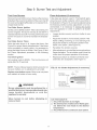
Step 9 Burner Test and Adjustment
Install any loose components, such as burner caps
and grates that may have been removed earlier. Be
certain that burner caps seat properly into the burner
bases. Before testing operation of the appliance,
verify that the unit and the gas supply have been
carefully checked for leaks and that the unit has been
connected to the electrical power supply. Turn the
manual gas shut-off valve to the open position.
Test Rangetop Burners
Test Burner Ignition. Select a rangetop burner
knob. Push in and turn counterclockwise to HI. The
ignitor/spark module will produce a clicking sound.
Once the air has been purged from the supply lines,
the burner should light within four (4) seconds.
Test Flame: High Setting. Turn burner on to HI. See
Figure 9 for appropriate flame characteristics.
If any of the rangetop burners continue to burn mostly
or completely yellow, verify that the burner cap is
positioned properly on the burner base, then re-test. If
flame characteristics do not improve, call
Thermador@.
Test Flame: Low Setting. Turn burner on to LO.
Verify that the flame completely surrounds the burner.
There should be a flame at each burner port and there
should be no air gap between the flame and the
burner. If any burners do not carry over, call
Thermador@.
The two far left burners feature XLO®, causing the
flame to cycle on and off when the knob is set to the
XLO range. This is normal operation.
Repeat the Ignition and Flame Test procedures de-
scribed above for each rangetop burner and the grill
burner (if so equipped).
FIG. 9 Flame Characteristics
Yellow Flames:
Further adjustment is required.
Yellow Tips on Outer Cones:
Normal for LP Gas.
Soft Blue Flames:
Normal for Natural Gas.
Ifthe flame iscompletely or mostly yellow, verify that the
regulator is set for the correct fuel. After adjustment,
retest.
Some orange-colored streaking is normal during the
initial start-up.
Allow unit tooperate 4-5 minutes and re-evaluate before
making adjustments.
WHEN FLAME IS PROPERLY ADJUSTED:
. There should be a flame at each burner port.
. There should be no air gap between the flame
and burner port.
The gas grill uses a tube-style burner that has an air
shutter which allows adjustment to the amount of
primary air inside the burner tube.
Air shutters of tube-style burners are pre-adjusted at
the factory, and usually do not require re-adjustment
except under rare conditions such as installation at
high altitude.
If grill burner/flame adjustment is required, go to the
procedure: "Flame Adjustment (if necessary)".
16

Step 9: Burner Test and Adjustment
Test Oven Burners
Remove the oven bottom cover. Remove the 4 screws
that attach the cover to the bottom of the oven, then lift
the cover and angled baffle plate out to expose the U-
shaped bake burner.
Test Bake Burner mgnition
Set the oven to BAKE at 350°F. After a short delay, the
burner will ignite. The burner will stay lit until 350°F is
reached and then shutoff. From this point forward, the
burner will cycle on and off to maintain the tempera-
ture.
Test Bake Burner Flame
While the bake burner is lit, inspect the flame. See
Figure 9 for proper flame characteristics. If the flame
burns completely or mostly yellow, it is necessary to
adjust the bake burner air shutter. See Figure 10 and
the Flame Adjustment procedure in the following
section.
Test Broil mgnition
Set cooking mode to BROIL. The broil burners will
ignite after 30-75 seconds.
F_ame Adjustment _if necessary}i."
Tube-style gas burners used in Thermador© appli-
ances have air shutter systems which are similar to
the illustration in Figure 10, and can be adjusted using
the following method (unless adjustment is not rec-
ommended). It is necessary to remove the burner
from the appliance in order to perform air-shutter
adjustments.
• Loosen shutter screw(s) and turn shutter to new
position.
• Adjust the shutter to more-closed position if the
flame is lifting or blowing, or is not carrying over.
Adjust the shutter to more-open position if the
flame is too yellow. (See Figure 10.)
• Re-tighten the shutter screw(s).
• After adjustment, re-installthe burnerand perform
flame evaluation. The air shutter must fit over the
orifice hood for proper operation of the burner.
• Repeat procedure as needed until flame char-
acteristics are acceptable. (See Figure 9.)
NOTE: The two infrared ceramic broil burners do not
have air shutters, so no adjustment is provided.
RepLace oven bottom cover. Slide cover into place
and reattach to bottom of oven cavity.
WARNtNG
Burner adjustments must be performed by a
qualified technician. Rmproper adjustments may
cause harmfu_ by-products or void the
appliance's warranty.
AHow burners to coo_ before attempting to
remove them!
F_G. 10 Air Shutter Adjustment (if necessary)
Screw
More Carryover
Less Lifting or Blowing
Call Thermador@ if:
1. Any of the burners do not light.
2. The broil burner or bake burner flame goes
out before the oven heats to the desired
temperature.
3. Any of the burners continue to burn yellow.
17
La page est en cours de chargement...
La page est en cours de chargement...
La page est en cours de chargement...
La page est en cours de chargement...
La page est en cours de chargement...
La page est en cours de chargement...
La page est en cours de chargement...
La page est en cours de chargement...
La page est en cours de chargement...
La page est en cours de chargement...
La page est en cours de chargement...
La page est en cours de chargement...
La page est en cours de chargement...
La page est en cours de chargement...
La page est en cours de chargement...
La page est en cours de chargement...
La page est en cours de chargement...
La page est en cours de chargement...
La page est en cours de chargement...
La page est en cours de chargement...
La page est en cours de chargement...
La page est en cours de chargement...
La page est en cours de chargement...
La page est en cours de chargement...
-
 1
1
-
 2
2
-
 3
3
-
 4
4
-
 5
5
-
 6
6
-
 7
7
-
 8
8
-
 9
9
-
 10
10
-
 11
11
-
 12
12
-
 13
13
-
 14
14
-
 15
15
-
 16
16
-
 17
17
-
 18
18
-
 19
19
-
 20
20
-
 21
21
-
 22
22
-
 23
23
-
 24
24
-
 25
25
-
 26
26
-
 27
27
-
 28
28
-
 29
29
-
 30
30
-
 31
31
-
 32
32
-
 33
33
-
 34
34
-
 35
35
-
 36
36
-
 37
37
-
 38
38
-
 39
39
-
 40
40
-
 41
41
-
 42
42
-
 43
43
-
 44
44


Thermador PRG366EPG/01 Guide d'installation
- Catégorie
- Fours
- Taper
- Guide d'installation
- Ce manuel convient également à
dans d''autres langues
Documents connexes
-
Thermador 336 Manuel utilisateur
-
-
-
-
Thermador PCD24EE01 Guide d'installation
-
-
-
-
Thermador PD366BS/08 Guide d'installation
-
Thermador PRD304EHC/04 Guide d'installation