Miller MC320546J Le manuel du propriétaire
- Catégorie
- Système de soudage
- Taper
- Le manuel du propriétaire
Ce manuel convient également à

OWNER’S MANUAL
© 2020 Miller Electric Mfg. LLC
FORM: OM-245021D 2020-06
RFCS - RJ45 Foot Control For Welding Power Sources
1. Safety Symbol Definitions
DANGER! − Indicates a hazardous situation which, if not
avoided, will result in death or serious injury. The possible haz-
ards are shown in the adjoining symbols or explained in the text.
DANGER ! - Indique une situation dangereuse qui, si elle n’est
pas évitée, entraînera la mort ou des blessures graves. Les
éventuels risques sont représentés par les symboles joints ou
expliqués dans le texte.
Fsafe1 2013-10
Beware of electric shock from welding electrode or wiring.
Touching the electrode while in contact with the work or
ground can cause electric shock. Always wear dry
gloves. Keep all panels and covers closed.
Attention au risque d’électrocution due au contact avec
l’électrode de soudage ou les fils. Le fait de toucher
l’électrode tout en étant en contact avec la pièce ou la
terre peut provoquer une électrocution. Toujours porter
des gants secs. Tous les panneaux et couvercles doivent
rester fermés.
Fsafe6 2018-01
Indicates a hazardous situation which, if not avoided, could result
in death or serious injury. The possible hazards are shown in the
adjoining symbols or explained in the text.
Indique une situation dangereuse qui, si elle n’est pas évitée,
entraînera la mort ou des blessures graves. Les éventuels
risques sont représentés par les symboles joints ou expliqués
dans le texte.
Fsafe2 2013-10
Wear safety glasses with side shields.
Porter des lunettes de sécurité avec écrans latéraux.
Fsafe8 2013-10
NOTICE
Indicates statements not related to personal injury.
Signale des consignes non associées aux dommages corporels.
Indicates special instructions.
Fournit des instructions spéciales.
Fsafe3 2013-10
Arc rays can burn eyes and skin − wear a welding helmet
with correct filter, and cover exposed skin with nonflam-
mable clothing.
Le rayonnement de l’arc peut provoquer des brûlures au
niveau des yeux ou de la peau – porter un casque protec-
teur muni d’un écran de filtre approprié et porter des vête-
ments non inflammables pour protéger toutes parties
exposées.
Fsafe11 2018-01
Have only trained and qualified persons install, operate,
or service this unit. Read the safety information at the
beginning of these instructions and in each section. Call
your distributor if you do not understand the directions.
For WELDING SAFETY and EMF information, read own-
er’s manual(s).
Ne confiez l’installation, l’exploitation ou l’entretien de cet
appareil qu’à des personnes compétentes et qualifiées. Lire
les directives de sécurité au début de ces instructions et
dans chaque section. Appeler votre distributeur si vous
ne comprenez pas les directives. Lire le(s) manuel(s)
d’utilisateur pour des renseignements sur la SÉCURITÉ
DE SOUDAGE et les champs électromagnétiques.
Fsafe15 2013-10
Welding sparks can cause fire or explosion. Move flam-
mables away. Do not weld on closed tanks or barrels, or
on containers that have held combustibles − they can
explode. Clean tanks or barrels properly.
Les étincelles de soudure peuvent provoquer un incendie
ou une explosion. Ne pas souder de cuves ou de ton-
neaux, au risque qu’ils explosent. Nettoyer soigneuse-
ment les cuves ou tonneaux.
Fsafe9 2018-01
CALIFORNIA PROPOSITION 65 WARNINGS
WARNING: Cancer and Reproductive Harm −
www.P65W
arnings.ca.gov
PROPOSITION CALIFORIENNE 65
AVERTISSEMENTS
AVERTISSEMENT : cancer et troubles de la repro-
duction − www.P65W
arnings.ca.gov
.
Fsafe26 2018-01
Breathing welding fumes and gases can harm your
health. Welding requires good ventilation. If ventilation is
impossible, such as when welding in a confined space,
use an air-supplied respirator.
L’inhalation des fumées et des gaz de soudure peut être
dangereuse pour la santé. Une bonne ventilation est
nécessaire pour procéder au soudage. S’il est impossible
de ventiler, dans des lieux confinés par exemple, utiliser
un respirateur à alimentation d’air.
Fsafe10 2018-01
2. Software Licensing Agreement
The End User License Agreement and any third-party notices and terms and conditions pertaining to third-party software can be found at
https://www
.millerwelds.com/eula
and are incorporated by reference herein.
3. Information About Default Weld Parameters And Settings
NOTICE − Each welding application is unique. Although certain Miller Electric products are designed to determine and default to certain typical welding
parameters and settings based upon specific and relatively limited application variables input by the end user, such default settings are for reference
purposes only; and final weld results can be affected by other variables and application-specific circumstances. The appropriateness of all parameters
and settings should be evaluated and modified by the end user as necessary based upon application-specific requirements. The end user is solely
responsible for selection and coordination of appropriate equipment, adoption or adjustment of default weld parameters and settings, and ultimate
quality and durability of all resultant welds. Miller Electric expressly disclaims any and all implied warranties including any implied warranty of fitness
for a particular purpose.

OM-810 Page 2
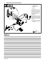
4. Typical Connections And Operation
805465-A
1. Welding Power Source Foot
Control Receptacle
2. Strain Relief (Optional
Installation)
3. Cord
4. Foot Control
If desired, route cord through strain
relief. Remove screw, as shown,
from welding power source, and
use screw to secure strain relief.
Plug one end of cord into receptacle
on welding power source.
OPERATION:
Press pedal lightly to turn weld
output and gas flow on. Press pedal
further to increase weld output.
Raise pedal to reduce amperage,
crater-out, and turn off weld output
and gas flow.
. See welding power source
Owner’s Manual for additional
information.
Tools Needed:
1
3
2
4
Torx T25
Notes

OM-810 Page 3
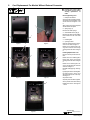
5. Cord Replacement For Models Without External Connector
! Unplug foot control cable
from power source before
starting replacement of
cable.
Removing Existing Cord.
1. Phillips Head Screws
Squeeze pedal and base together,
and remove the two Phillips head
screws as shown in Figures 1 and
2.
After screws are removed, lift pedal
off base. Retain the pedal.
2. Springs (Fig. 3)
Remove and retain springs.
3. Strain Relief Screws (Fig. 3)
Remove and retain the two Phillips
head screws from the cord strain
relief.
4. Retaining Tab
5. Opening In Base
Depress retaining tab and discon-
nect cord as shown in Figure 4.
Rotate cord so retaining tab is fa-
cing down. Remove cord through
opening in base as shown in Figure
5.
Installing Replacement Cord.
Reverse removal procedure as fol-
lows:
Rotate new cord so retaining tab is
facing down. Feed cord through
opening in base as shown in Figure
5.
Rotate cord so retaining tab is fa-
cing up and plug tab into connector
as shown in Figure 4.
Reinstall existing springs. See Fig-
ure 3.
Lightly tighten the two existing Phil-
lips head screws to secure cord
with strain relief (do not crush cord).
See Figure 3.
Set pedal on base.
Squeeze pedal and base together.
Secure pedal to base with existing
Phillips head screws. See Figures
1 and 2.
Tools Needed:
Figure 1
Figure 2
Figure 3 Figure 4
Figure 5
Phillips Screwdriver
1
1
1
2
2
5
4
3

OM-810 Page 4
6. Troubleshooting
Trouble Remedy
No weld output Be sure foot control cord is plugged into matching receptacles on welding power source and inside of
the foot control.
Not enough weld amperage Set weld amperage to highest desired value on welding power source Material Thickness/Amperage
control. Amperage available with foot control is 10 amps to max value set on Thickness/Amperage
control.
7. Parts List
Description
Part
No.
245589
Item
No. Quantity
RFCS−RJ45 (Foot Control)
1 245044 RFCS-RJ45 Foot Control (Pedal Only) 1... .......... ..... .............................
2 237676 Cable, w/Connectors 14 Ft 1... .......... ..... ........................................
3 235493 Clamp, Stl Cush .187 Dia x .281 Mtg Hole Zinc Pld 1... .......... ..... ...................
To maintain the factory original performance of your equipment, use only Manufacturer’s Suggested
Replacement Parts. Model and serial number required when ordering parts from your local distributor.
-
 1
1
-
 2
2
-
 3
3
-
 4
4


Miller MC320546J Le manuel du propriétaire
- Catégorie
- Système de soudage
- Taper
- Le manuel du propriétaire
- Ce manuel convient également à
dans d''autres langues
- English: Miller MC320546J Owner's manual
Documents connexes
-
Miller PROHEAT SERIES ADAPTOR (195 437) Le manuel du propriétaire
-
-
-
Miller LE28 Le manuel du propriétaire
-
-
-
Miller MA27 Le manuel du propriétaire
-
Miller MJ395009V Le manuel du propriétaire
-
-
Miller PIPEWORX 400 SYSTEM (380-400 VOLT CE) Le manuel du propriétaire