Klein Tools CL120 Manuel utilisateur
- Catégorie
- Mesure, test
- Taper
- Manuel utilisateur
Ce manuel convient également à

INSTRUCTION MANUAL
600V
400A
20M
Ω
FRANÇAIS pg. 25
ESPAÑOL pg. 13
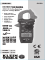
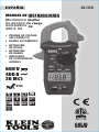
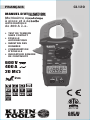
400A AC Auto-Ranging
Digital Clamp Meter
INSTRUCTION MANUAL
400A AC Auto-Ranging
Digital Clamp Meter
400A AC Auto-Ranging
Digital Clamp Meter
• NON-CONTACT
VOLTAGE TESTING
• AUTO-RANGING
• DATA HOLD
• RANGE HOLD
• AUDIBLE
CONTINUITY
ENGLISH
CL120
2m
CAT III
600V

2
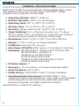
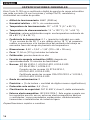
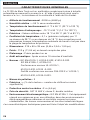
GENERAL SPECIFICATIONS
Klein Tools CL120 is an automatically ranging digital clamp-meter
that measures AC current via the clamp, and AC/DC voltage,
resistance and continuity via test-leads.
• Operating Altitude: 6562 ft. (2000 m)
• Relative Humidity: <95% non-condensing
• Operating Temp: 32° to 122°F (0° to 50°C)
• Storage Temp: 14° to 122°F (-10° to 50°C)
• Accuracy: Values stated at 65° to 83°F (18° to 28°C)
• Temp Coefcient: 0.1 x (Quoted Accuracy) per °C above
28°C or below 18°C, corrections are required when ambient
working temp is outside of Accuracy Temp range
• Dimensions: 8.46" x 3.54" x 1.50" (215 x 90 x 38 mm)
• Weight: 11.04 oz. (313 g) including batteries
• Calibration: Accurate for one year
• Auto Power-Off (APO): After approx. 10 minutes of inactivity
• Standards: IEC EN 61010-1, 61010-2-032, 61010-2-033.
IEC EN 61326-1, 61326-2-2.
Conforms to UL STD.61010-1,
61010-2-032,61010-2-033;
Certified to CSA STD.C22.2 NO. 61010-1,
61010-2-032,61010-2-033.
• Pollution degree: 2
• Accuracy: ± (% of reading + # of least significant digits)
• Drop Protection: 6.6 ft. (2m)
• Safety Rating: CATIII 600V, Class 2, Double insulation
• Electromagnetic Environment: IEC EN 61326-1. This
equipment meets requirements for use in basic and controlled
electromagnetic environments like residential properties,
business premises, and light-industrial locations.
Specifications subject to change.
ENGLISH

3
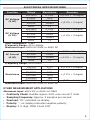
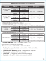
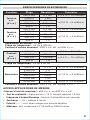
ELECTRICAL SPECIFICATIONS
Function Range Resolution Accuracy
AC Voltage
(V AC)
200.0mV 0.1mV ±(2.5% + 10 digits)
2.000V 1mV
±(2.0% + 5 digits)
20.00V 10mV
200.0V 100mV
600V 1V
DC Voltage
(V DC)
200.0mV 0.1mV ±(1.0% + 8 digits)
2.000V 1mV
±(1.0% + 3 digits)
20.00V 10mV
200.0V 100mV
600V 1V
Input Impedance: 10MΩ
Frequency Range: 45 to 400Hz
Maximum Input: 600V AC RMS or 600V DC
AC Current
(A AC)
2.000A 1mA ±(2.5% + 30 digits)
20.00A 10mA
±(2.0% + 10 digits)200.0A 100mA
400A 1A
Frequency Range: 50 to 60Hz
Resistance
200.0Ω 0.1Ω ±(1.2% + 5 digits)
2.000KΩ 1Ω
±(1.2% + 3 digits)
20.00kΩ 10Ω
200.0kΩ 100Ω
2.000MΩ 1kΩ
20.00MΩ 10kΩ ±(2.0% + 5 digits)
Maximum Input: 600V AC RMS or 600V DC
OTHER MEASUREMENT APPLICATIONS
Maximum Input: 600V DC or 600V AC RMS
• Continuity Check: Audible signal <10Ω, max current 1.5mA
• Sampling Frequency: Approx. 3 samples per second
• Overload: "OL" indicated on display
• Polarity: "-" on display indicates negative polarity
• Display: 3 ½ digit, 2000 Count LCD

4
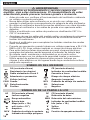
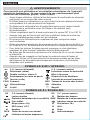
WARNINGS
To ensure safe operation and service of the meter, follow these
instructions. Failure to observe these warnings can result in
severe injury or death.
• Before each use verify meter operation by measuring a known
voltage or current.
• Never use the meter on a circuit with voltages that exceed the
category based rating of this meter.
• Do not use the meter during electrical storms or in wet weather.
• Do not use the meter or test leads if they appear to be damaged.
• Use only with CAT III or CAT IV rated test leads.
• Ensure meter leads are fully seated, and keep fingers away
from the metal probe contacts when making measurements.
• Do not open the meter to replace batteries while the probes
are connected.
• Use caution when working with voltages above 25V AC RMS
or 60V DC. Such voltages pose a shock hazard.
• To avoid false readings that can lead to electrical shock,
replace batteries when a low battery indicator appears.
• Do not attempt to measure resistance or continuity on a live circuit.
• Always adhere to local and national safety codes. Use personal
protective equipment to prevent shock and arc blast injury
where hazardous live conductors are exposed.
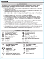
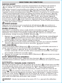
SYMBOLS ON METER
AC (Alternating Current) DC (Direct Current)
Resistance (in Ohms) Audible Continuity
Double Insulated Class II Ground
Warning or Caution
Risk of Electrical Shock
V Voltage (Volts) A Amperage (Amps)
COM Common NCV Non-Contact Voltage Tester
Backlight SEL Select
+
Positive
–
Negative
SYMBOLS ON LCD
AC AC (Alternating Current) DC DC (Direct Current)
Negative Reading
H
Data Hold
Auto Ranging MAX Maximum Value Hold
Low Battery Audible Continuity
M
Mega (value x 10
6
)
k
kilo (value x 10
3
)
m
milli (value x 10
-3
)
V
Volts
A
Amps Ohms
NCV
Non-Contact Voltage Tester Auto Power-Off
Hazardous Voltage Indicator
ENGLISH

5
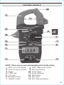
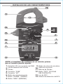
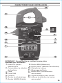
FEATURE DETAILS
1
6
2
9
3
10
14
5
8
7
4
NOTE: There are no user-serviceable parts inside meter.
1.
2000 count LCD display
8.
"MAX" (Maximum) button
2.
Function selector switch
9.
Data Hold button
3.
Clamp
10.
Clamp trigger
4.
"COM" jack
11.
Arrow markings
5.
"VΩ" jack
12.
NCV Button
6.
Backlight button
13.
NCV Light
7.
"RANGE" button
14.
NCV Sensing Antenna
11
12
13

6
FUNCTION BUTTONS
ON/OFF
To power ON the meter, rotate the Function Selector switch
2
from
the OFF setting to any measurement setting. To power OFF the meter,
rotate the Function Selector switch
2
to the OFF setting. The Auto-
Power Off icon
will be visible in the display. By default, the meter
will automatically power OFF after 10 minutes of inactivity. If the meter
automatically powers-OFF while in a measurement setting, press any
button to power the meter ON, or rotate Function Selector
2
switch
to OFF, then power ON the meter. To deactivate Auto-Power OFF
functionality press and hold the "NCV" button
12
before powering ON
from the OFF setting. When Auto-Power OFF is deactivated, the Auto-
Power Off icon
will not be visible in the display.
BACKLIGHT
Press Backlight button symbol
6
to turn ON or OFF the backlight.
The backlight does not automatically power OFF.
RANGE
The meter defaults to auto-ranging mode
. This mode
automatically determines the most appropriate measurement range
for the testing that is being conducted.
To manually force the meter to
measure in a different range, use the
"RANGE"
button
7
.
1. Press the "RANGE" button
7
to manually select measurement
range (
is deactivated on the LCD). Repeatedly press the
"RANGE" button
7
to cycle through the available ranges,
stopping once the desired range is reached.
2. To return to auto-ranging mode, press and hold the "RANGE"
button
7
for more than two seconds ( is reactivated).
MAX
When the "MAX" button
8
is pressed, the meter keeps track of the
Maximum value as the meter continues to take samples.
1. When measuring, press "MAX" button
8
to display the
maximum value. If a new maximum occurs, the display
updates with that new value.
2. Press "MAX" button
8
again to return to normal measuring mode.
DATA HOLD
Press the Data Hold button
9
to hold the current measurement on
the display. Press again to return to live measuring mode.
NCV
Press and hold the "NCV" button
12
to enter Non-contact Voltage
Testing (NCV) mode to test for presence of AC voltage.
The NCV
icon and "EF" will be present on the display. Approach the conductor
under test leading with the sensing antenna
14
. In the presence of
AC voltage, the red NCV light
13
will illuminate and audible signals
(beeps) will sound.
As the NCV sensing antenna
13
approaches
the voltage source, the frequency of the audible sound will increase.
Release the "NCV" button to exit NCV testing mode.
NOTE: Only voltages of 40V AC or greater will be detected.
ENGLISH

7
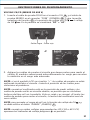
OPERATING INSTRUCTIONS
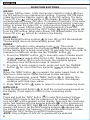
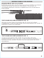
CONNECTING TEST LEADS
Do not test if leads are improperly seated. Results could cause
intermittent display readings. To ensure proper connection, firmly
press leads into the input jack completely.
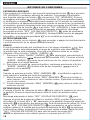
TESTING IN CAT III MEASUREMENT LOCATIONS
Ensure the test lead shield is pressed firmly in place. Failure to use
the CATIII / CATIV shield increases arc-flash risk.
TESTING IN CAT II MEASUREMENT LOCATIONS
CAT III / CAT IV shields may be removed for CAT II locations. This
will allow testing on recessed conductors such as standard wall
outlets. Take care not to lose the shields.
5/32"
(4 mm)
.7" (18 mm)
INCORRECT
CORRECT

8
ENGLISH
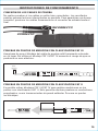
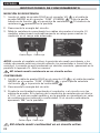
OPERATING INSTRUCTIONS
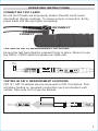
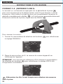
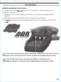
AC CURRENT (LESS THAN 400A)
AC Current is measured by pressing the clamp trigger
10
to open
the clamp and placing it around a current-carrying wire. When
measuring, care should be taken to ensure that the clamp is
completely closed with trigger
10
fully released, and that the wire
passes perpendicularly through the center of the clamp in line with
the arrow markings
11
.
To measure current:
1. Rotate the Function Selector switch
2
to the 200/400 A setting.
2. Place clamp around wire. The current measurement will be shown
in the display.
NOTE: If the measurement is less than 20A, rotate the Function
Selector switch
2
to the 2/20 A setting for improved resolution.
Disconnect test leads when measuring with the clamp.
WIRE

9
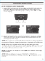
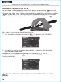
OPERATING INSTRUCTIONS
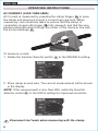
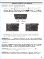
AC/DC VOLTAGE (LESS THAN 600V)
1. Insert RED test lead into VΩ jack
5
, and BLACK test lead into
COM jack
4
, and rotate function selector switch
2
to the
DC Voltage
or AC Voltage setting. Note "DC" or "AC"
on the display.
2. Apply test leads to the circuit to be tested to measure voltage.
The meter will auto-range to display the measurement in the
most appropriate range.
NOTE: If "–" appears on the LCD, the test leads are being applied to
the circuit in reverse. Swap the position of the leads to correct this.
NOTE: When in a voltage setting and the test leads are open,
readings of order mV may appear on the display. This is noise and
is normal. By touching the test leads together to close the circuit
the meter will measure zero volts.
NOTE: To access mV range for V AC
the "RANGE" button
7
must be used.
NOTE: When voltages in excess of 25V AC or 60V DC are
measured, the Hazardous Voltage Indicator
will appear on the
display.
OR
Red leadBlack lead

10
ENGLISH
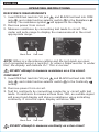
OPERATING INSTRUCTIONS
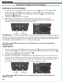
RESISTANCE MEASUREMENTS
1. Insert RED test lead into VΩ jack
5
, and BLACK test lead into COM
jack
4
, and rotate function selector switch
2
to the Resistance
setting. The resistance symbol will appear on the display.
2. Remove power from circuit.
3. Measure resistance by connecting test leads to circuit. The
meter will auto-range to display the measurement in the most
appropriate range.
NOTE: When in a Resistance setting and the test leads are open
(not connected across a resistor), or when a failed resistor is under
test, the display will indicate O.L. This is normal.
DO NOT attempt to measure resistance on a live circuit.
CONTINUITY
1. Insert RED test lead into VΩ jack
5
and BLACK test lead into COM
jack
4
, and rotate function selector switch
2
to the Continuity
setting.
2. Remove power from circuit.
3. Test for continuity by connecting conductor or circuit with test
leads. If resistance is measured less than 10Ω, an audible signal
will sound and display will show a resistance value indicating
continuity. If circuit is open, display will show "OL".
DO NOT attempt to measure continuity on a live circuit.
Red leadBlack lead
Red leadBlack lead

11
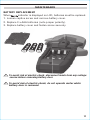
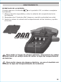
MAINTENANCE
BATTERY REPLACEMENT
When indicator is displayed on LCD, batteries must be replaced.
1. Loosen captive screw and remove battery cover.
2. Replace 3 x AAA batteries (note proper polarity).
3. Replace battery cover and fasten screw securely.
T
o avoid risk of electric shock, disconnect leads from any voltage
source before removing battery door.
To avoid risk of electric shock, do not operate meter while
battery door is removed.

ENGLISH
CLEANING
Be sure meter is turned off and wipe with a clean, dry lint-free
cloth.
Do not use abrasive cleaners or solvents.
STORAGE
Remove the batteries when meter is not in use for a prolonged
period of time. Do not expose to high temperatures or
humidity. After a period of storage in extreme conditions
exceeding the limits mentioned in the General Specifications
section, allow the meter to return to normal operating
conditions before using.
WARRANTY
www.kleintools.com/warranty
DISPOSAL / RECYCLE
Do not place equipment and its accessories in the trash.
Items must be properly disposed of in accordance with local
regulations. Please see www.epa.gov or www.erecycle.org
for additional information.
CUSTOMER SERVICE
KLEIN TOOLS, INC.
450 Bond Street
Lincolnshire, IL 60069
1-877-775-5346
www.kleintools.com

MANUAL DE INSTRUCCIONES
Multímetro digital
de ganchode rango
automáticode
400A CA
MANUAL DE INSTRUCCIONES
Multímetro digital
de ganchode rango
automáticode
Multímetro digital
de ganchode rango
automáticode
• PRUEBA DE VOLTAJE
SIN CONTACTO
• RANGO AUTOMÁTICO
• RETENCIÓN
DE DATOS
• RETENCIÓN
DE RANGO
• INDICADOR
DE CONTINUIDAD
AUDIBLE
CL120
600 V
400 A
20 M
Ω
2m
ESPAÑOL
CAT III
600V

14
ESPECIFICACIONES GENERALES
Klein Tools CL120 es un multímetro digital de gancho de rango automático
que mide corriente CA con las pinzas y voltaje CA/CD, resistencia y
continuidad con cables de prueba.
• Altitud de funcionamiento: 6562' (2000m)
• Humedad relativa: <95%, sin condensación
• Temperatura de funcionamiento: 32° a 122°F (0° a 50°C)
• Temperatura de almacenamiento: 14° a 122°F (-10° a 50°C)
• Precisión: valores establecidos según una temperatura ambiente de
65 a 83°F (18 a 28°C)
• Coeciente de temperatura: 0,1 × (precisión indicada) por cada
°C por encima de los 28°C o por debajo de los 18°C, esnecesario
realizar correcciones si la temperatura del ambiente de trabajo se
encuentra fuera del rango de precisiónde temperatura
• Dimensiones: 8,46" × 3,54" × 1,50" (215 × 90 × 38mm)
• Peso: 11,04 oz (313g) incluidas las baterías
• Calibración: precisa durante un año
• Función de apagado automático (APO): después de
aproximadamente 10minutos de inactividad
• Normas: IECEN61010-1, 61010-2-032, 61010-2-033.
IECEN61326-1, 61326-2-2.
Cumple con las normas UL STD.61010-1,
61010-2-032, 61010-2-033;
Certificado según las normas CSA STD.C22.2 n.º 61010-1,
61010-2-032, 61010-2-033.
• Grado de contaminación: 2
• Precisión: ± (% de lectura + cantidad de dígitos menos significativos)
• Protección ante caídas: 6,6' (2m)
• Clasicación de seguridad: CATIII 600V, clase 2, doble aislamiento
• Entorno electromagnético: IEC EN 61326-1. Este equipo cumple con
los requisitos para su uso en entornos electromagnéticos básicos
y controlados, como propiedades residenciales, establecimientos
comerciales e instalaciones deindustria ligera.
Especificaciones sujetas a cambios.
ESPAÑOL

15
ESPECIFICACIONES ELÉCTRICAS
Función Rango Resolución Precisión
Voltaje CA
(V CA)
200,0mV 0,1mV ± (2,5% + 10dígitos)
2,000V 1mV
± (2,0% + 5dígitos)
20,00V 10mV
200,0V 100mV
600V 1V
Voltaje CD
(V CD)
200,0mV 0,1mV ± (1,0% + 8dígitos)
2,000V 1mV
± (1,0% + 3dígitos)
20,00V 10mV
200,0V 100mV
600V 1V
Impedancia de entrada: 10MΩ
Rango de frecuencia: 45 a 400Hz
Entrada máxima: 600V CA RMS o 600V CD
Corriente CA
(A CA)
2,000A 1mA ± (2,5% + 30dígitos)
20,00A 10mA
± (2,0% + 10dígitos)200,0A 100mA
400A 1A
Rango de frecuencia: 50 a 60Hz
Resistencia
200,0Ω 0,1Ω ± (1,2% + 5dígitos)
2,000kΩ 1Ω
± (1,2% + 3dígitos)
20,00kΩ 10Ω
200,0kΩ 100Ω
2,000MΩ 1kΩ
20,00MΩ 10kΩ ± (2,0% + 5dígitos)
Entrada máxima: 600V CA RMS o 600V CD
OTRAS APLICACIONES DE MEDICIÓN
Entrada máxima: 600V CD o 600V CA RMS
• Vericación de continuidad: señal audible < 10Ω, 1,5mA de
corrientemáxima
• Frecuencia de muestreo: aprox. 3 muestras por segundo
• Sobrecarga: se indica “OL” en la pantalla
• Polaridad: “-” en pantalla indica polaridad negativa
• Pantalla: LCD de 3 ½ dígitos con recuento de 2000

16
ADVERTENCIAS
Para garantizar un funcionamiento y servicio seguros del
medidor, siga estas instrucciones. El incumplimiento de estas
advertencias puede provocar lesiones graves o la muerte.
• Antes de cada uso, verifique el funcionamiento del multímetro midiendo
un voltaje o corriente conocidos.
• Nunca debe utilizar este multímetro en un circuito con voltajes que
excedan la clasificación correspondiente a la categoría de este multímetro.
• No utilice el multímetro durante tormentas eléctricas o en clima húmedo.
• No utilice el multímetro o los cables de prueba si en apariencia están
dañados.
• Utilice el multímetro con cables de prueba con clasificación CATIII o
CATIV únicamente.
• Asegúrese de que los cables del medidor estén correctamente colocados
y mantenga los dedos lejos de los contactos de la sonda de metal al
realizar las mediciones.
• No abra el multímetro para reemplazar las baterías mientras las sondas
están conectadas.
• Proceda con precaución cuando trabaje con voltajes superiores a 25VCA
RMS o 60VCD. Esos voltajes implican un riesgo de choque eléctrico.
• Para evitar lecturas falsas que puedan provocar choques eléctricos,
reemplace las baterías cuando aparezca el indicador de batería baja.
• No intente medir resistencia o continuidad en un circuito activo.
• Cumpla siempre con los códigos de seguridad locales y nacionales.
Utilice equipo de protección personal para prevenir lesiones por
choque y arco eléctrico en los lugares donde haya conductores activos
peligrosos expuestos.
SÍMBOLOS DEL MEDIDOR
CA (corriente alterna) CD (corriente directa)
Resistencia (en ohmios) Indicador de continuidad audible
Doble aislamiento Clase II Conexión a tierra
Advertencia o precaución
Riesgo de choque eléctrico
V Voltaje (voltios) A Amperaje (amperios)
COM Común NCV Probador de voltaje sin contacto
Retroiluminación SEL Seleccionar
+
Positivo
–
Negativo
SÍMBOLOS DE LA PANTALLA LCD
AC CA (corriente alterna) DC CD (corriente directa)
Lectura negativa
H
Retención de datos
Rango automático MAX Retención del valor máximo
Batería baja
Indicador de continuidad audible
M
Mega (valor × 10
6
)
k
kilo (valor × 10
3
)
m
mili (valor × 10
-3
)
V
Voltios
A
Amperios Ohmios
NCV
Probador de voltaje sin contacto
Función de apagado automático
Indicador de voltaje peligroso
ESPAÑOL

17
DETALLES DE LAS CARACTERÍSTICAS
1
6
2
9
3
10
14
5
8
7
4
NOTA: el medidor no contiene en su interior piezas
que el usuario pueda reparar.
1.
Pantalla LCD con recuento de 2000
9.
Botón de retención de datos
2.
Perilla selectora de función
10.
Gatillo de las pinzas
3.
Pinzas
11.
Marcas de flechas
4.
Conector “COM”
12.
Botón “NCV” (VOLTAJE
SINCONTACTO)
5.
Conector “VΩ”
6.
Botón de retroiluminación
13.
Luz de NCV
7.
Botón “RANGE” (RANGO)
14.
Antena de detección de NCV
8.
Botón “MAX” (MÁXIMO)
11
12
13

18
BOTONES DE FUNCIONES
ENCENDIDO/APAGADO
Para encender el multímetro, gire la perilla selectora de función
2
de la posición
OFF (APAGADO) a cualquier posición de medición. Para apagar el multímetro,
gire la perilla selectora de función
2
a la posición “OFF” (APAGADO). El icono
de apagado automático
será visible en la pantalla. Deforma predeterminada,
elmultímetro se apagará automáticamente después de 10minutos de inactividad.
Si el multímetro se apaga automáticamente cuando se encuentra en un parámetro
de medición, presione cualquier botón para volver a encender el multímetro, ogire
la perilla selectora de función
2
a la posición “OFF” (APAGADO) y luego encienda
el multímetro. Para desactivar la función de apagado automático, mantenga
presionado el botón “NCV” (VOLTAJE SIN CONTACTO)
12
antes de encender la
unidad desde la posición “OFF” (APAGADO). Al desactivar la función de apagado
automático, el icono correspondiente
no se visualiza en la pantalla.
RETROILUMINACIÓN
Presione el botón con el símbolo
6
para encender o apagar la retroiluminación.
La retroiluminación no se apaga automáticamente.
RANGO
El modo predeterminado del multímetro es el de rango automático . Este
modo determina automáticamente el rango de medición más adecuado para
la prueba que se está realizando. Para que el multímetro mida en un rango
diferente, utilice el botón “RANGE” (RANGO)
7
.
1. Presione el botón “RANGE” (RANGO)
7
para seleccionar manualmente el
rango de medición (
desaparece de la pantalla LCD). Presione el botón
“RANGE” (RANGO)
7
varias veces para recorrer los rangos disponibles y
deténgase en el rango deseado.
2. Para volver al modo de rango automático, mantenga presionado el botón
“RANGE” (RANGO)
7
durante más de dos segundos ( vuelve a
aparecer en la pantalla).
MAX
Cuando se presiona el botón “MAX” (MÁXIMO)
8
, el multímetro registra el
valor máximo a medida que toma las muestras.
1. Mientras mide, presione el botón “MAX” (MÁXIMO)
8
para visualizar el
valor máximo. Si se detecta un valor máximo nuevo, la pantalla se actualiza
con el valor nuevo.
2. Vuelva a presionar el botón “MAX” (MÁXIMO)
8
para volver al modo de
medición normal.
RETENCIÓN DE DATOS
Presione el botón de retención de datos
9
para retener la medición en curso en
la pantalla. Presione nuevamente para volver al modo de medición activo.
NCV
Mantenga presionado el botón “NCV” (VOLTAJE SIN CONTACTO)
12
para
ingresar al modo de prueba de voltaje sin contacto (NCV) y probar la presencia
de voltaje CA. El icono NCV y “EF” aparecerán en la pantalla. Acerque la antena de
detección
14
al conductor que desee probar. Ante la presencia de voltaje CA, laluz
roja de “NCV” (VOLTAJE SIN CONTACTO)
13
se encenderá y se oirán señales
audibles (pitidos). A medida que la antena de detección de NCV
13
se aproxima
a la fuente de voltaje, aumentará la frecuencia del sonido audible. Suelte el botón
“NCV” (VOLTAJE SIN CONTACTO) para salir del modo de prueba NCV.
NOTA:
se detectarán solo voltajes iguales o mayores que 40VCA.
ESPAÑOL

19
INSTRUCCIONES DE FUNCIONAMIENTO
CONEXIÓN DE LOS CABLES DE PRUEBA
No realice pruebas si los cables no están bien conectados. Los resultados
podrían generar lecturas intermitentes en pantalla. Para garantizar una buena
conexión, presione los cables firmemente en el conector de entrada hasta el
final.
PRUEBAS EN PUNTOS DE MEDICIÓN CON CLASIFICACIÓN CATIII
Asegúrese de que el blindaje del cable de prueba esté firmemente colocado
en su lugar. No utilizar el blindaje CATIII/CATIV aumenta el riesgo de que se
produzca un arco eléctrico.
PRUEBAS EN PUNTOS DE MEDICIÓN CON CLASIFICACIÓN CATII
Es posible retirar blindajes CATIII/CATIV para realizar mediciones en los
puntos con clasificación CATII. Esto permite efectuar pruebas en conductores
empotrados, como tomacorrientes de pared estándar. Procure no perder
losblindajes.
5/32"
(4 mm)
.7" (18 mm)
INCORRECTO
CORRECTO

20
INSTRUCCIONES DE FUNCIONAMIENTO
CORRIENTE CA (MENOS DE 400A)
La corriente CA se mide presionando el gatillo de las pinzas
10
para que
estas se abran y colocándolas alrededor del cable que conduce la corriente.
Almedir, se debe tener cuidado de cerrar bien las pinzas soltando el gatillo
10
por completo, y de que el cable pase perpendicularmente a través del
centro de las pinzas y quede alineado con las marcas de flechas
11
.
Para medir la corriente realice lo siguiente:
1. Gire la perilla selectora de función
2
a la posición de 200/400A.
2. Coloque las pinzas alrededor del cable. La medición de corriente
aparecerá en la pantalla.
NOTA: si el resultado de la medición es inferior a 20A, gire la
perilla selectora de función
2
a la posición de 2/20A para obtener
mejorresolución.
Desconecte los cables de prueba cuando mida con las
pinzas.
CABLE
CABLE
CABLE
ESPAÑOL
La page est en cours de chargement...
La page est en cours de chargement...
La page est en cours de chargement...
La page est en cours de chargement...
La page est en cours de chargement...
La page est en cours de chargement...
La page est en cours de chargement...
La page est en cours de chargement...
La page est en cours de chargement...
La page est en cours de chargement...
La page est en cours de chargement...
La page est en cours de chargement...
La page est en cours de chargement...
La page est en cours de chargement...
La page est en cours de chargement...
La page est en cours de chargement...
-
 1
1
-
 2
2
-
 3
3
-
 4
4
-
 5
5
-
 6
6
-
 7
7
-
 8
8
-
 9
9
-
 10
10
-
 11
11
-
 12
12
-
 13
13
-
 14
14
-
 15
15
-
 16
16
-
 17
17
-
 18
18
-
 19
19
-
 20
20
-
 21
21
-
 22
22
-
 23
23
-
 24
24
-
 25
25
-
 26
26
-
 27
27
-
 28
28
-
 29
29
-
 30
30
-
 31
31
-
 32
32
-
 33
33
-
 34
34
-
 35
35
-
 36
36


Klein Tools CL120 Manuel utilisateur
- Catégorie
- Mesure, test
- Taper
- Manuel utilisateur
- Ce manuel convient également à
dans d''autres langues
- español: Klein Tools CL120 Manual de usuario
Documents connexes
-
Klein Tools CL120KIT Mode d'emploi
-
Klein Tools CL110 Mode d'emploi
-
-
Klein Tools CL220 Manuel utilisateur
-
-
-
-
-
-
Klein Tools 69355 Mode d'emploi
Autres documents
-
Ideal Vol-Con® Elite Digital Voltage Tester w/Vibration Mode Mode d'emploi
-
-
-
-
Extech Instruments CA250 Manuel utilisateur
-
-
-
-
-