Kicker 2019 CXA 5-Channel Amplifiers Le manuel du propriétaire
- Taper
- Le manuel du propriétaire

CX
AMPLIFIERS
Owner’s Manual
CXA660.5
Manual del Propietario | Español
AMPLIFICADOR DEL LA SERIE CX.5
Benutzerhandbuch | Deutsch
VERSTÄRKER DER CX.5-SERIE
Manuel d’utilisation | Française
AMPLIFICATEUR DE SÉRIE CX.5

2
CX.5-SERIES AMPLIFIERS
OWNER’S MANUAL
PERFORMANCE
Authorized KICKER Dealer:
Purchase Date:
Serial Number:
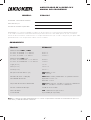
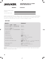
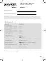
Model: CXA660.5
RMS Power, AMP1 and AMP2
@ 14.4V, 4Ω stereo, ≤ 1% THD+N
@ 14.4V, 2Ω stereo, ≤ 1% THD+N
@ 14.4V, 4Ω mono, ≤ 1% THD+N
65W x 4
90W x 4
180W x 2
RMS Power, SUB channel
@ 14.4V, 4Ω mono, ≤ 1.5 % THD+N
@ 14.4V, 2Ω mono, ≤ 1.5 % THD+N
150W x 1
300W x 1
Length [in, cm] 14, 30
Height [in, cm] 2-3/8, 5.9
Width [in, cm] 6-3/4, 17
Frequency Response [Hz] AMPS 1-2: 10–20k
SUB: 25–200
Signal-to-Noise Ratio [dB] >90dB, A-weighted, re: rated power
Input Sensitivity Low Level: 250mV–10V
High Level: 1V–40V
Selectable Electronic Crossover AMPS 1-2: HI or OFF; Variable 10–200Hz @ 12dB/Octave
SUB: LO; 50–200Hz @ 12dB/Octave
KickEQ™ Bass Boost Variable 0–6dB @ 40Hz
Subsonic Filter SUB: 24dB/Octave, Fixed @ 25Hz
Remote Bass: Yes [sold separately]
Pro Tip: To get the best performance from your new KICKER Amplifi er and extend the warranty by 1 year, use
genuine KICKER accessories and wiring.
MODEL: CXA660.5
WARNING: KICKER products are capable of producing sound levels that can permanently damage your hearing! Turning up a
system to a level that has audible distortion is more damaging to your ears than listening to an undistorted system at the same
volume level. The threshold of pain is always an indicator that the sound level is too loud and may permanently damage your
hearing. Please use common sense when controlling volume.

3
INSTALLATION
Mounting: Choose a structurally sound location to mount your KICKER amplifi er. Make sure there are no items
behind the area where the screws will be driven. Choose a location that allows at least 4” (10cm) of open
ventilation for the amplifi er. If possible, mount the amplifi er in the climate-controlled passenger compartment. Drill
four holes using a 7/64” (3mm) bit and use the supplied #8 screws to mount the amplifi er.
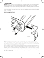
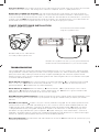
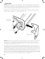
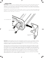
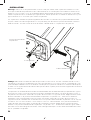
The KICKER CX Amplifi ers are capable of space-saving vertical mounting. Use a 2.5mm hex key (Allen wrench)
to loosen the endpanel, remove the existing brackets, then insert and tighten the double-slotted brackets to the
amplifi er as illustrated.
double-slotted
bracket
hex screws
amplifi er side panel
VERTICAL MOUNTING
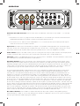
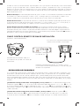
Wiring: Disconnect the vehicle’s battery to avoid an electrical short. Then, connect the ground wire to the
amplifi er. Make the ground wire short, 24” (60cm) or less, and connect it to a paint-and-corrosion-free, solid,
metal area of the vehicle’s chassis. Adding an additional ground wire of this same gauge (or larger) between the
battery’s negative post and the vehicle chassis is recommended.
The CX amplifi er has dual input sensitivity differential RCA inputs which will receive either high or low level signals
from your car stereo’s source unit. A high-level signal can be run from the source unit’s speaker outputs to the
stereo RCA input on the end panel of the amplifi er using the KICKER KISL as shown (make sure you set the CX
amplifi er’s input level switch to “HI”). Alternatively, the signal can be delivered to the amplifi er using the low-level
RCA outputs on the source unit; set the input level switch on the end panel of the amplifi er to “LO”. Keep the
audio signal cable away from factory wiring harnesses and other power wiring. If you need to cross this wiring,
cross it at a 90 degree angle.

4
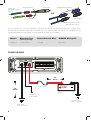
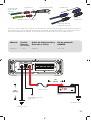
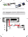
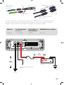
POWER WIRING
12V
GND REM +12V
battery
external fuse
remote turn-on
(see page 6)
bare-metal
chassis ground
bare-metal
chassis ground
≤18”
(45cm)
≤24”
(60cm)
Model External Fuse
(sold separately)
Power/Ground Wire KICKER Wiring Kit
CXA660.5 1 x 80 Ampere 4 Gauge PK4, CK4
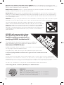
Install a fuse within 18” (45cm) of the battery and in-line with the power cable connected to your amplifi er. If you
ever need to remove the amplifi er from the vehicle after it has been installed, the ground wire should be the last
wire disconnected from the amplifi er--just the opposite as when you installed it.
source unit
high-level speaker
outputs
to amplifi er
shield
+
–
core conductor
OR
KICKER KISL (optional)
from source unit high-
level speaker outputs
to amplifi er

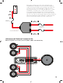
5
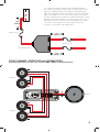
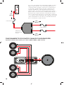
AMP1
AMP2
SUB
L R S
SL R
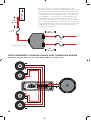
FOUR CHANNEL OPERATION with SUBWOOFER
minimum impedance of 2 ohms per channel (AMP1, AMP2, and SUB channels)
speakers
speakers
woofer
external fuse
external fuses
distribution block
≤18”
(45cm)
≤18”
(45cm)
≤18”
(45cm)
12V
For multiple amplifi er installations where distribution blocks
are used, each amplifi er should have its proper-rated fuse, or
breaker, installed between the amplifi er and the distribution
block within eighteen inches of the block, or on the distribution
block if it provides for fusing. The primary power wire should
also be fused between the battery and distribution block, within
eighteen inches of the battery’s positive terminal, with a fuse
or breaker rated at least to the sum of the individual amplifi er’s
fuse values. Use wiring of the same gauge and current
capacity as your power and ground wires.

6
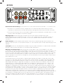
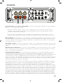
OPERATION
6
Automatic Turn-On Selection: The CX series offers two different automatic turn-on modes; +12V and DC
Offset.
• Remote Turn-On: Run 18 gauge wire from the Remote Turn-On Lead on your source unit to the terminal
labeled REM between the amplifi er’s positive and negative power terminals.
• DC Offset Turn-On: The DC Offset mode detects a >2.5V DC offset from the HI-Level speaker outputs
when the source unit has been turned on.
Input Level: The RCA inputs on KICKER CX amplifi ers are capable of receiving either Hi or Low-level signals
from your source unit. If the only output available from your source unit is a Hi-Level signal, simply press in the
Input Level switch on the amplifi er. Refer to the wiring section of this manual for additional instructions.
Fader Switch: Depress the fader switch if you are running two sets of inputs (front and rear for example) to the
amplifi er. Leave the fader switch OFF if you want to drive all channels from a single stereo input.
Sub Input: If there is no dedicated output on your source unit for a subwoofer, use the SUB INPUT switch to set
your subwoofer input to either SUB INPUT or AMP INPUT 2.
Input Gain Control: The input gain control is not a volume control. It matches the output of the source unit to
the input level of the amplifi er. Maximum power out of the amplifi er is possible with the gain in the lowest position.
Incorrectly setting the gain can result in distorted output or damage to, and premature failure of, your speakers. For
a quick setup, turn the source unit up to about 3/4 volume (if the source unit goes to 30, turn it to 25). Slowly turn
up (clockwise) the gain on the amplifi er until you can hear audible distortion, then turn it down a little.
To use the preferred method of setting the input gain using a voltmeter or oscilloscope, begin by turning off the
amplifi er and disconnecting all speakers from it. Turn the gain knob completely off (counterclockwise) and all
crossovers off, or to their least effective setting. Turn the bass boost knob completely off (counterclockwise). If a
remote bass accessory is connected to the amplifi er, turn it completely on (clockwise). Ensure all EQ and DSP
settings on the source unit such as bass, treble, fader, seating position etc are set to linear, fl at, center, or off. Turn
on the amplifi er. Play a 0dB sine wave through your source unit and increase the volume to about 3/4 of maximum.
Sine wave tracks can be downloaded for free from KICKER.com under the “Support” tab. Use the 50Hz sine wave
to set the gain for a subwoofer and the 1kHz sine wave for full-range speakers. Set your voltmeter or oscilloscope
to measure AC voltage. Place the voltmeter’s probes on the amplifi er’s speaker output terminals. With the sine wave
playing, slowly turn the gain knob clockwise and watch the AC voltage on the voltmeter increase. When the desired
voltage is shown (reference power chart insert), or you start to see the waveform square off stop increasing the
gain, turn the amplifi er off, reconnect all speakers and set the crossovers to your desired setting. Your gain is now
set for maximum unclipped power from the amplifi er. If you increase amplitude using settings on the source unit or
the bass boost on the amplifi er it will introduce distortion and you will need to redo these steps.
Bass Boost Control: The variable bass boost control on the top of the amplifi er is designed to give you
increased output, 0–6dB, at 40 Hz. The setting for this control is subjective. If you turn it up, you must readjust
the input gain control to avoid clipping the amplifi er.
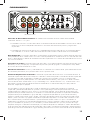
audio inputs

7
6
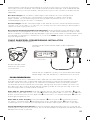
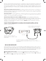
CXARC REMOTE BASS INSTALLATION
(Optional - CXARC not included.)
back view
Surface-mount the CXARC remote
using the supplied screws.
Remote cable passes audio; do not
run cable parallel to power wires.
Connect the supplied 1/8th inch [3.5mm] patch cable to the
CXARC remote and the Remote Bass jack on the amplifi er
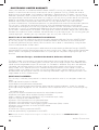
TROUBLESHOOTING
If your amplifi er does not appear to be working, check the obvious things fi rst such as blown fuses, poor or incorrect
wiring connections, incorrect setting of crossover switch and gain controls, etc. There are Power (PWR) & Protection
(PRT) LEDs on the side panel of your Kicker CX series amplifi er. Depending on the state of the amplifi er and the
vehicle’s charging system, the LEDs will glow either green or red. When the green LED is lit, this indicates the amplifi er
is turned on and no trouble exists.
Green LED off, no output? With a Volt Ohm Meter (VOM) check the following:
+12 volt power terminal (should
read +12V to +16V)
Remote turn-on terminal (should read +12V to +16V)
Check for reversed power and
ground connections
Ground terminal, for proper conductivity.
Green LED on, no output? Check the following:
RCA connections
Test speaker outputs with a “known”
good speaker.
Substitute source unit with a “known” good source unit.
Check for a signal in the RCA cable
feeding the amplifi er with the VOM meter set to measure “AC” voltage.
Red LED fl ickering with loud music? The red LED indicates low battery voltage. Check all the connections in your
vehicle’s charging system. It may be necessary to replace or charge your vehicle’s battery or replace your vehicle’s
alternator.
Red LED on, no output?
Amplifi er is very hot = thermal protection is engaged. Test for proper impedance at the
speaker terminals with a VOM meter (see the diagrams in this manual for minimum recommended impedance and
multiple speaker wiring suggestions). Also check for adequate airfl ow around the amplifi er.
Amplifi er shuts down
= voltage protection circuitry is engaged. Voltage to the amplifi er is not within the 8–16 volt operating range. Have
the vehicle’s charging and electrical system inspected.
Amplifi er will only play at low volume levels = short circuit
protection is engaged. Check for speaker wires shorted to each other or to the vehicle chassis. Check for damaged
speakers or speaker(s) operating below the minimum recommended impedance.
No or low output?
Check the balance and fader controls on source unit
Check the RCA (or speaker input) and
speaker output connections.
Crossover Control: The variable crossovers on the side panel of the amplifi er allow you to adjust the crossover
frequency from 50Hz–200Hz. The setting for this control is subjective; 80Hz is a good place to start.
Remote Bass-CXARC (not included): With the CXARC remote bass level control, you have the ability to
control the output level of the amplifi er remotely. To surface-mount the CXARC remote bass level control, simply
screw the remote to the chosen location, then run the cable from the controller to the “Remote Bass” jack on the
amplifi er panel. Do NOT connect/disconnect while the amplifi er is on. Connecting the 3.5mm cable without the
remote knob will cause the amplifi er to output at full gain, possibly damaging your speakers.

8
KICKER will now provide a three-
year warranty with all CX-Series
Amplifi er purchases paired with a
qualifying KICKER Installation Kit* .
This extends the standard warranty by an additional
year. Amplifi er and Kit must be purchased from an
Authorized KICKER Dealer.
KICKER CX amplifi er success is currently at an unheard-of rate, making the extended
warranty program even more benefi cial to you.
Using poor-quality, under-spec wiring kits will impede CX amplifi er performance.
A superior-quality KICKER installation Kit is guaranteed to extend the life of CX
amplifi ers.
The new extended warranty applies only to KICKER amplifi ers and accessories sold to consumers by Authorized
KICKER Dealers in the United States of America or its possessions. It also only applies to the original purchaser of
KICKER amplifi ers and accessories. One warranty extension per amplifi er is allowed regardless of the number of amplifi er
installation kits purchased. This program does not apply to “B”-stock product or factory-refurbished product.
This offer is for a limited time, so see your local Authorized KICKER Dealer soon for details.
*U.S.A. Only | EE.UU. solamente | Nur USA | Les USA Seulement
CXA660.5
AMPS 1 & 2: 65 x 4 @ 4 ohms
Signal to Noise Ratio -75dB CEA-2006B (ref: 1W, A-weighted)
SUB: 150 x 1 @ 4 ohms (25Hz–200Hz)
Signal to Noise Ratio -75dB CEA-2006B (ref: 1W, A-weighted)
14.4VDC, 1% THD, CEA-2006B (Watts)
Alternator noise-whining sound with engine’s RPM?
Check for damaged RCA (or speaker input) cable
Check the routing of RCA (or speaker input) cable
Check the source unit for proper grounding
Check the gain
settings and turn them down if they are set too high.
Reduced bass response? Reverse a speaker connection from positive to negative on the stereo/subwoofer
channel(s); if the bass improves, the speaker was out of phase.
Ground Noise? KICKER amplifi ers are engineered to be fully compatible with all manufacturers’ head units. Some
head units may require additional grounding to prevent noise from entering the audio signal. If you are experiencing
this problem with your head unit, in most cases running a ground wire from the RCA outputs on the head unit to the
chassis will remedy this issue.
CAUTION: When jump starting the vehicle, be sure that connections made with jumper cables are correct. Improper
connections can result in blown amplifi er fuses as well as the failure of other critical systems in the vehicle.
If you have more questions about the installation or operation of your new KICKER
product, see the Authorized KICKER Dealer where you made your purchase. For more
advice on installation, click on the SUPPORT tab on the KICKER homepage, www.
kicker.com. Choose the TECHNICAL SUPPORT tab, choose the subject you are
interested in, and then download or view the corresponding information. Please E-mail
support@kicker.com or call Technical Services (405) 624-8583 for unanswered or
specifi c questions.

9
Modelo: CXA660.5
Potencia RMS, AMP1 y AMP2
@ 14.4V, 4Ω estéreo, ≤ 1% THD+N
@ 14.4V, 2Ω estéreo, ≤ 1% THD+N
@ 14.4V, 4Ω mono, ≤ 1% THD+N
65W x 4
90W x 4
165W x 2
Potencia RMS, SUB canal
@ 14.4V, 2Ω monofónico, ≤ 1.5% THD+N
@ 14.4V, 4Ω monofónico, ≤ 1.5% THD+N
300W x 1
150W x 1
Largo [in. cm] 14, 30
Altura [in. cm] 2-3/8, 5.9
Ancho [in. cm] 6-3/4, 17
Respuesta de frecuencias [Hz] AMPS 1-2: 10–20k
SUB: 25–200
Relación de señal a ruido [dB] AMPS 1-2: >90dB, ponderado-A, re: potencia nominal
Sensibilidad de entrada Bajo Nivel: 250mV–10V
Alto Nivel: 1V–40V
Separador de frecuencia electrónico AMPS 1-2: HI o OFF; variable 10–200Hz @ 12dB/octava
SUB: LO; variable 50–200Hz @ 12dB/octava
KickEQ™ Refuerzo de Bajos 0–6dB @ 40Hz variable
Filtro subsónico SUB: 24dB/Octava, Fijo @ 25Hz
Grave remoto Sí [se vende por separado]
AMPLIFICADOR DE LA SERIE CX.5
MANUAL DEL PROPIETARIO
RENDIMIENTO
Distribuidor autorizado de KICKER:
Fecha de compra:
Número de serie del amplifi cador:
Nota: Para obtener el mejor rendimiento de sus nuevos amplifi cadores KICKER, le recomendamos que use
accesorios y cableado KICKER auténticos.
MODELO: CXA660.5
ADVERTENCIA: Los excitadores KICKER son capaces de producir niveles de sonido que pueden dañar permanentemente
el oído. Subir el volumen del sistema hasta un nivel que produzca distorsión es más dañino para el oído que escuchar un
sistema sin distorsión al mismo volumen. El dolor es siempre una indicación de que el sonido es muy fuerte y que puede dañar
permanentemente el oído. Sea precavido cuando controle el volumen.

10
soporte de doble
ranura
tornillos hexagonales
panel de fondo
del amplifi cador
INSTALACIÓN
Montaje: Escoja un lugar estructuralmente sólido para montar el amplifi cador KICKER. Asegúrese de que no
haya nada por detrás de dónde van a entrar los tornillos. Escoja un lugar en que queden por lo menos 4 plg.
(10 cm) de espacio abierto de ventilación alrededor del amplifi cador. Si es posible, monte el amplifi cador en el
compartimiento de pasajeros, con ambiente acondicionado. Haga cuatro agujeros con una broca de 7/64 de
plg. (3 mm) y monte el amplifi cador con los tornillos N° 8 que se suministran.
Los Amplifi cadores CX de KICKER se pueden instalar verticalmente para ahorrar espacio. Use una llave
hexagonal de 2,5mm (llave Allen) para afl ojar el panel de fondo, quite los soportes existentes, luego inserte y
apriete los soportes de doble ranura al amplifi cador como se ilustra.
Cableado: Desconecte la batería del vehículo para evitar cortocircuitos. Luego, conecte un cable de conexión
a tierra al amplifi cador. El cable de conexión a tierra debe ser corto, de 24 plg. (60 cm) o menos, y debe
ir conectado a un punto sólido del chasis del vehículo en que no haya ni pintura ni corrosión. También se
recomienda instalar un cable de conexión a tierra adicional, de este mismo calibre (o de mayor calibre), entre la
terminal negativa de la batería y el chasis del auto.
El amplifi cador CX tiene entradas RCA diferenciales de doble sensibilidad de entrada que reciben señales de
alto nivel o bajo nivel de la unidad fuente del sistema estereofónico del automóvil.La señal se puede llevar al
amplifi cador desde las salidas de altavoz de alto nivel de la unidad fuente. Fije el selector de nivel de entrada del
panel de extremo del amplifi cador en la posición de alto (HI). Engarce y suelde conectores RCA al extremo del
cable de altavoz procedente de las salidas de altavoz de alto nivel de la unidad fuente y conéctelo a las entradas
RCA del panel de extremo del amplifi cador o simplifi car la instalación mediante un KISL KICKER como se
muestra a continuación. Como alternativa, puede conectar producción de su unidad fuente a las entradas RCA
del amplifi cador CX RCA. Fije el selector de nivel de entrada del panel de extremo del amplifi cador en la posición
de bajo (LO). Mantenga el cable de señal de audio alejado de los arneses de cableado de fábrica y otros cables
de alimentación. Si es necesario cruzar este cableado, crúcelo en un ángulo de 90°.

11
12V
GND REM +12V
batería
fusible externo
encendido a distancia
(página 13)
conexión a tierra
conexión a tierra
≤18”
(45cm)
≤24”
(60cm)
Hacia el
amplifi cador
KICKER KISL
Cable de salida de
altavoz de alto nivel
Modelo Fusible
Externo
(no incluido)
Cable de Alimentación y
Conexión a Tierra
Kit de cableado
KICKER
CXA660.5 1 x 80A Calibre 4 PK4, CK4
Cable de salida
de altavoz de
alto nivel
Hacia el amplifi cador
Conexión a tierra o blindaje
+
–
cable central
Instale un fusible a menos de 18 plg. (45 cm) de la batería y en línea con el cable de alimentación conectado al
amplifi cador. Si alguna vez necesita desmontar el amplifi cador, el cable de conexión a tierra debe ser el último
que se desconecte del amplifi cador. Exactamente lo contrario de lo que se hace cuando se instala.
O

12
AMP1
AMP2
SUB
L R S
SL R
FUNCIONAMIENTO POR CUATRO CANALES CON SUBWOOFER
impedancia mínima de 2 ohmios por canales (AMP1, AMP2, y SUB canales)
fusible externo
fusible externo
≤18”
(45cm)
≤18”
(45cm)
≤18”
(45cm)
12V
Para varias instalaciones de amplifi cadores donde se utilizan
bloques de distribución, cada amplifi cador debe poseer su
fusible de grado apropiado, o interruptor, instalado entre el
amplifi cador y el bloque de distribución a dieciocho años
pulgadas del bloque, o sobre el bloque de distribución si
admite fusibles. El principal cable de alimentación también
debe fusionarse entre la batería y el bloque de distribución, a
dieciocho años pulgadas del terminal positivo de la batería,
con un fusible o interruptor con una clasifi cación al menos de
la suma de los valores individuales del fusible del amplifi cador.
Utilice cableado del mismo calibre y capacidad de corriente
que su alimentación y cables de tierra.
Bloqueo de
distribución de
energía

13
señal de entrada
FUNCIONAMIENTO
6
Selección de Encendido Automático: El modelo CX le ofrece dos distintos modos de encendido
automático; desvío a +12V y DC.
• Encendido a Distancia: Instale cable calibre 18 desde el conductor de encendido a distancia de la unidad
fuente hasta la terminal etiquetada REM entre las terminales de alimentación positiva y negativa del
amplifi cador.
• Encendido por Compensación de CC: En la modalidad de compensación de CC, el amplifi cador detecta
una subida de >2.5V de las salidas de altavoz de alto nivel cuando la unidad fuente se ha encendido.
Nivel de Entrada: Las entradas RCA de los amplifi cadores CX de KICKER aceptan señales de bajo nivel o alto
nivel procedentes de la unidad fuente. Si la única salida disponible de la unidad fuente es una señal de alto nivel,
oprima y deje adentro el selector de nivel de entrada del amplifi cador. En la sección de cableado de este manual
hay más instrucciones.
Interruptor de “Fader”: Presione el interruptor de “Fader” si está ejecutando dos conjuntos de entradas (parte
delantera y trasera, por ejemplo) al amplifi cador. Deja el interruptor de apagado, si usted quiere manejar todos
los canales de entrada estéreo de un solo.
Entrada de Subwoofer: Si no hay salida dedicada al subwoofer en la unidad fuente, fi je el selector de entrada
de subwoofer (SUB INPUT) en la posición AMP2 o en la posición SUB.
Control de Amplifi cación de Entrada: El control de amplifi cación de entrada no es un control de volumen. El
control de amplifi cación de entrada hace que la salida de la fuente corresponda al nivel de entrada del amplifi cador.
La potencia máxima del amplifi cador es posible con la ganancia en la posición más baja. La confi guración
incorrecta de la ganancia puede provocar una salida distorsionada o daños y fallas prematuras de los altavoces.
Suba el volumen de la unidad fuente a ¾ (si la unidad llega a 30, súbale el volumen a 25). A continuación, suba
lentamente la amplifi cación (girando el control en el sentido de las manecillas del reloj) hasta que pueda oír
distorsión, luego bájela un poquito.
Para establecer la ganancia de entrada usando un voltímetro o un osciloscopio, comience apagando el
amplifi cador y desconectando todos los parlantes. Gire la perilla de ganancia completamente hacia afuera (en
sentido antihorario) y todos los cruces, o hacia su ajuste menos efectivo. Gire la perilla de refuerzo de graves
completamente (en sentido antihorario). Si se conecta un accesorio de bajo remoto al amplifi cador, enciéndalo
completamente (en el sentido de las agujas del reloj). Asegúrese de que todos los ajustes de ecualización y
DSP en la unidad fuente, como graves, agudos, atenuador, posición de asiento, etc. estén confi gurados como
lineales, planos, centrales o apagados. Enciende el amplifi cador. Reproduzca una onda 0dB sinusoidal a través
de su unidad fuente y aumente el volumen a aproximadamente 3/4 de máximo. Las pistas sinusoidales se
pueden descargar de forma gratuita desde KICKER.com en la pestaña “Soporte”. Utilice la onda sinusoidal de
50Hz para establecer la ganancia para un subwoofer y la onda senoidal de 1kHz para los parlantes de rango
completo. Confi gure su voltímetro o osciloscopio para medir el voltaje de CA. Coloque las sondas del voltímetro
en los terminales de salida del altavoz del amplifi cador. Con la onda sinusoidal en reproducción, gire lentamente la
perilla de ganancia en el sentido de las agujas del reloj y observe cómo aumenta la tensión de CA en el voltímetro.

14
RESOLUCIÓN DE PROBLEMAS
Si su amplifi cador parece no estar funcionando, revise lo obvio primero: fusibles quemados, conexiones malas
o incorrectas, posición incorrecta de los selectores de crossover y amplifi cación, etc. Su amplifi cador modelo
CX de KICKER cuenta con los LED de protección (PRT) y de encendido (PWR) en el panel de alimentación
lateral. Dependiendo del estado del amplifi cador y del sistema de carga del vehículo, los LED se iluminarán en
verde o en rojo. Cuando el LED se ilumina en verde, indica que el amplifi cador está encendido y no hay ningún
problema.
¿El indicador luminoso LED verde está apagado y no hay salida? Con un voltímetro/ohmímetro (VOM),
verifi que lo siguiente:
Hay +12V en la terminal de alimentación (debe leerse entre +12V y +16V).
Hay +12V
en la terminal de encendido a distancia (debe leerse entre +12V y +16V).
No hay conexiones invertidas de
alimentación o conexión a tierra.
La terminal de conexión a tierra tiene la conductividad adecuada.
No hay
fusibles quemados.
¿El Indicador luminoso LED verde está encendido y no hay salida? Verifi que lo siguiente:
Las
conexiones RCA están bien.
Las salidas de altavoces están bien pues han sido puestas a prueba con
un altavoz en buenas condiciones.
Se ha cambiado la unidad fuente por una unidad fuente en buenas
CXARC CONTROL REMOTO DE BAJOS INSTALACIÓN
(Opcional - no incluido CXARC)
vista desde atrás
Para instalar en superfi cie el control remoto
CXARC use los tornillos suministrados.
Cable de control remoto de audio pasa,
no se ejecutan en paralelo a los cables de
alimentación.
Conecte el cable de extensión de 1/8 pulgadas [3.5mm]
suministrado al control remoto CXARC y a la entrada de grave
remoto en el amplifi cador.
Cuando se muestra la tensión deseada, o que empiece a ver la plaza de forma de onda de parada aumentando la
ganancia, apagar el amplifi cador, vuelva a conectar todos los altavoces y establecer los cruces a la confi guración
deseada. Su ganancia ahora está confi gurada para la máxima potencia no eliminada del amplifi cador. Si aumenta la
amplitud usando los ajustes en la unidad fuente o la potencia de graves en el amplifi cador, introducirá distorsión y
deberá repetir estos pasos.
Refuerzo de Bajos: El control de potenciador de graves variable a un costado del amplifi cador está diseñado
para ofrecer una salida incrementada, 0–6dB, a 40Hz. La confi guración para este control es subjetiva. Si la
aumenta, puede reajustar el control de ganancia de entrada para evitar recortar el amplifi cador.
Control de Crossover: El separador de frecuencias variable en el costado del amplifi cador le permite ajustar
la frecuencia del separador de frecuencia de paso bajo de 10 a 200Hz (AMPS 1 & 2) y 50 a 200Hz (SUB). La
confi guración para estos controles es subjetiva; 80Hz es un buen punto para empezar.
Control Remoto de Bajos-CXARC (no incluido): Con el control remoto de nivel de graves CXARC
opcional, puede controlar a distancia el nivel de salida del amplifi cador. Para instalar en superfi cie el control
remoto de nivel de graves CXARC, simplemente atornille el control en la ubicación elegida, luego extienda el
cable del controlador hacia la entrada “Remote Bass” (grave remoto) en el panel del amplifi cador. NO conectar /
desconectar, mientras que el amplifi cador está encendido.

15
CXA660.5
65 x 4 @ 4 ohmios (20Hz–20,000Hz)
Relación de Señal a Ruido -75dB CEA-2006B (ref: 1W, ponderado en A)
150 x 1 @ 4 ohmios (25Hz–200Hz)
Relación de Señal a Ruido -75dB CEA-2006B (ref: 1W, ponderado en A)
14.4VCC, 1% THD, CEA-2006B (W)
condiciones.
Con un medidor VOM confi gurado para medir voltaje de “CA”, se ha buscado una señal en el
cable RCA que alimenta el amplifi cador.
¿El indicador luminoso LED de “protection” destella con la música fuerte? El indicador luminoso
LED rojo indica que hay bajo voltaje de batería. Revise todas las conexiones del sistema de carga eléctrica del
vehículo. Puede ser necesario cambiar o cargar la batería del vehículo o cambiar el alternador del vehículo.
¿El indicador luminoso LED de “protection” está encendido y no hay salida?
El amplifi cador está
muy caliente = Se ha activado el circuito de protección térmica. Con un medidor VOM, compruebe que las
terminales de altavoz tengan la impedancia correcta (vea en este manual los diagramas que contienen datos de
impedancia mínima recomendada y sugerencias de cableado de varios altavoces). Asegúrese también de que
haya un fl ujo de aire adecuado alrededor del amplifi cador.
El amplifi cador se apaga sólo cuando el vehículo
está en marcha = Se ha activado el circuito de protección contra sobrevoltaje. El voltaje al amplifi cador no está
dentro del intervalo de funcionamiento de 8V a 16V. Haga inspeccionar el sistema eléctrico y de carga eléctrica
del automóvil.
El amplifi cador sólo funciona a bajo volumen = Se ha activado el circuito de protección contra
cortocircuitos. Asegúrese de que los cables de los altavoces no estén en cortocircuito entre sí o con el chasis
del vehículo. Vea si hay altavoces dañados o funcionando a menos de la impedancia mínima recomendada.
¿No hay salida de uno de los canales?
Revise el control de balance de la unidad fuente.
Revise las
conexiones RCA (o de entrada de altavoz) y de salida de altavoz del canal.
¿Hay ruido sibilante de alternador asociado a las RPM del motor?
Vea si hay algún cable RCA (o de
entrada de altavoz) dañado.
Revise el encaminamiento del cable RCA (o de entrada de altavoz).
Vea si la
unidad fuente tiene conexión a tierra apropiada.
Revise las confi guraciones de amplifi cación y bájelas si están
muy altas.
¿Hay baja respuesta de bajos? Invierta la conexión de uno de los altavoces de positiva a negativa en los
canales estereofónicos y/o de subwoofer; si los bajos mejoran, el altavoz estaba fuera de fase.
¿Hay ruido de conexión a tierra? Los amplifi cadores KICKER son totalmente compatibles con las unidades
fuente de todos los fabricantes. Algunas unidades principales pueden necesitar más conexión a tierra para
evitar que entre ruido a la señal de audio. En la mayoría de los casos, este problema con la unidad principal se
resuelve instalando un cable de conexión a tierra desde las salidas RCA de la unidad principal al chasis.
PRECAUCIÓN: Cuando haga arrancar el vehículo con cables de arranque conectados a una batería externa,
asegúrese de que las conexiones de los cables de arranque sean correctas. Conectar los cables de arranque
de manera incorrecta puede quemar los fusibles del amplifi cador y causar fallas en otros sistemas del vehículo.
Si tiene más preguntas sobre la instalación de su nuevo producto KICKER, vaya al
distribuidor autorizado de KICKER donde lo compró. Si necesita más consejos sobre la
instalación, haga clic en la lengüeta SUPPORT (apoyo) de la página Web de KICKER,
www.kicker.com. Escoja la lengüeta TECHNICAL SUPPORT (apoyo técnico), escoja
el tema que le interese y luego descargue o vea la información correspondiente. Envíe
un mensaje por correo electrónico a support@kicker.com o comuníquese con Servicios
Técnicos llamando al (405) 624-8583 si tiene preguntas específi cas o a las cuales no
haya encontrado respuesta.

16
Modell: CXA660.5
RMS-Leistung, AMP1 und AMP2
@ 14.4V, 4Ω stereo, ≤ 1% Gesamtklirrfaktor
@ 14.4V, 2Ω stereo, ≤ 1% Gesamtklirrfaktor
@ 14.4V, 4Ω mono, ≤ 1% Gesamtklirrfaktor
65W x 4
90W x 4
165W x 2
RMS-Leistung, SUB kanal
@ 14.4V, 2Ω mono, ≤ 1,5% Gesamtklirrfaktor
@ 14.4V, 4Ω mono, ≤ 1,5% Gesamtklirrfaktor
300W x 1
150W x 1
Länge [Zoll, cm] 14, 30
Höhe [Zoll, cm] 2-3/8, 5.9
Breite [Zoll, cm] 6-3/4, 17
Frequenzgang [Hz] AMPS 1 - 2: 10 – 20 k
SUB: 25 – 200
Rauschabstand [dB] >90 dB, A-bewertet: Nennleistung
Eingangsempfi ndlichkeit N-Pegel: 250mV–10V
H-Pegel: 1V–40V
Elektronischer Trennfrequenzregler AMPS 1-2: HI oder OFF; 10 – 200 Hz @ 12 dB/Oktave
SUB: LO; 50 – 200 Hz @ 12 dB/Oktave
KickEQ™ Bass-Boost Variabel 0 – 6 dB bei 40 Hz
Unterschallfi lter SUB: 24 dB/Oktave, fest bei 25 Hz
Remote-Bass Ja (separat erhältlich)
WARNUNG: KICKER-Treiber können einen Schallpegel erzeugen, der zu permanenten Gehörschäden führen kann! Wenn Sie ein
System auf einen Pegel stellen, der hörbare Verzerrungen erzeugt, schadet das Ihren Ohren mehr, als ein nicht verzerrtes System
auf dem gleichen Lautstärkepegel. Die Schmerzschwelle ist immer eine Anzeige dafür, dass der Schallpegel zu laut ist und zu
permanenten Gehörschäden führen kann. Seien Sie bei der Lautstärkeeinstellung bitte vernünftig!
VERSTÄRKER DER CX.5 SERIE
BENUTZERHANDBUCH
LEISTUNG
Autorisierter KICKER-Händler:
Kaufdatum:
Verstärker-Seriennummer:
Hinweis: Um das Maximum aus Ihrem neuen KICKER-Verstärker herauszuholen, sollten Sie echtes KICKER-
Zubehör und KICKER-Kabel verwenden.
MODELL: CXA660.5

17
INSTALLATION
Befestigung: Wählen Sie für die Installation des KICKER-Verstärkers eine strukturell stabile Stelle. Vergewissern
Sie sich, dass sich hinter der Einschraubposition der Schrauben nichts befi ndet. Wählen Sie eine Stelle, die
mindestens 10 cm Lüftungsfreiraum für den Verstärker bietet. Installieren Sie, wenn möglich, den Verstärker im
klimatisierten Fahrgastraum. Bohren Sie mit einem 3-mm-Bohrer vier Löcher und verwenden Sie die beiliegenden
Nr. 8-Schrauben zur Befestigung des Verstärkers.
Die KICKER CX-Verstärker können vertikal montiert werden, um Platz zu sparen. Schrauben Sie die Abdeckplatte
mit einem 2,5 mm Innensechskantschlüssel ab, entfernen Sie die vorhandenen Halterungen und bringen Sie die
doppelt geschlitzten Halterungen am Verstärker an.
Doppelt geschlitzte
Halterung
Verstärkerabdeckplatte
Sechskantschrauben
Anschluss: Trennen Sie den Anschluss der Fahrzeugbatterie, um einen Kurzschluss zu vermeiden. Schließen
Sie dann das Massekabel an den Verstärker an. Verwenden Sie ein kurzes Erdungskabel (maximal 60 cm) und
schließen Sie es an eine lack- oder korrosionsfreie Metallstelle an der Fahrzeugkarosserie an. Es wird auch
empfohlen, ein weiteres Massekabel mit gleicher (oder größerer) Drahtstärke zwischen dem negativen Pol der
Autobatterie und der Fahrzeugkarosserie zu verwenden.
Der CX-Verstärker hat zwei RCA-Eingänge mit Eingangsempfi ndlichkeits-Differential, die entweder Hoch- oder
Niedrigpegelsignale vom Autoradio empfangen. Kann das Signal mit den Hochpegel-Lautsprecherausgängen
am Autoradio an den Verstärker übertragen werden. Stellen Sie den Eingangspegelschalter an der Endplatte
des Verstärkers auf „HI“. Crimpen und löten Sie die RCA-Stecker an das Ende des Lautsprecherkabels von den
Hochpegel-Lautsprecherausgängen am Autoradio und verbinden Sie das Kabel mit den RCA-Eingängen an der
Endplatte des Verstärkers, oder Vereinfachung der Installation, indem Sie ein KICKER KISL wie unten gezeigt.
Alternativ können Sie Ihre Quelle Einheit Cinch-Ausgänge zum CX Verstärker Cinch-Eingänge anschließen.
Stellen Sie den Eingangspegelschalter an der Endplatte des Verstärkers auf „LO“. Achten Sie beim Verlegen
dieser Audiokabel darauf, dass sie Werks-Kabelbäume und andere Stromkabel nicht berühren. Wenn Sie die
Kabel überkreuzen müssen, tun Sie dies in einem 90-Grad-Winkel.

18
12V
GND REM +12V
Batterie
Ferneinschaltung
(Seite 20)
Masse
Masse
≤18”
(45cm)
≤24”
(60cm)
externe Sicherung
Modell Externe Sicherung
(nicht inbegriffen)
Massekabel KICKER Verkabelungssatz
CXA660.5 1 x 80 Ampere 4 GA PK4, CK4
Installieren Sie in maximal 45 cm Entfernung von der Batterie eine Sicherung in Reihe mit dem Stromkabel zum
Verstärker. Wenn Sie je den Verstärker nach der Installation aus dem Fahrzeug ausbauen müssen, sollte die
Masseleitung als letzte vom Verstärker getrennt werden, genau in der umgekehrten Reihenfolge wie bei der
Installation.
Hochpegel-
Lautsprecherausgangskabel
Zum Verstärker
Erdung oder Abschirmung
–
Kabelseele
ODER
+
KICKER KISL
Hochpegel-
Lautsprecherausgangskabel
Zum
Verstärker

19
AMP1
AMP2
SUB
L R S
SL R
VIERKANALBETRIEB MIT SUBWOOFER
Minimal impedanz von 2 Ohm pro Kanal (AMP1, AMP2, und SUB Kanäle)
≤18”
(45cm)
≤18”
(45cm)
≤18”
(45cm)
12V
Beim Einbau mehrerer Verstärker unter Verwendung von
Verteilerblöcken sollte jeder Verstärker eine ordnungsgemäß
zugelassene Sicherung oder Stromunterbrechung haben, die
zwischen Verstärker und Verteilerblock angebracht wird, in
einer Entfernung von 45 cm (18 Zoll) vom Block bzw. auf dem
Verteilerblock, falls dieser Platz für Überstromschutz bietet.
Das Hauptstromkabel sollte ebenfalls zwischen Batterie und
Verteilerblock gesichert werden, und zwar mit einem Abstand
von 45 cm (18 Zoll) zum Pluspol der Batterie mit einer Sicherung
oder Stromunterbrechung, die mindestens für die Summe der
Sicherungswerte der einzelnen Verstärker zugelassen ist.
Stromverteilerblock
externe
Sicherung
externe
Sicherung

20
BETRIEB
6
Automatische Einschaltung: Die CX-Serie umfasst zwei automatische Einschaltmodi: +12V und DC Offset.
• Remote Turn-On (Ferneinschaltung): Verlegen Sie 18 GA-Kabel von der Ferneinschaltung an Ihrem
Autoradio zum REM-Terminal zwischen den positiven und negativen Stromanschlüssen des Verstärkers.
• DC Offset-Einschaltung: Der DC Offset-Modus entdeckt nach Einschalten des Autoradios einen >2.5-Volt-
Anstieg an den Hochpegel-Lautsprecherausgängen.
Eingangspegel: Die RCA-Eingänge an KICKER CX-Verstärkern können entweder Hoch- oder
Niedrigpegelsignale vom Autoradio empfangen. Wenn nur ein H-Pegel-Signal vom Autoradio verfügbar ist,
drücken Sie einfach den Schalter „Input Level“ am Verstärker. Weitere Hinweise fi nden Sie im Abschnitt
„Anschluss“.
Fader-Schalter: Drücken Sie den Fader-Schalter, wenn Sie mit zwei der Eingänge (vorne und hinten zum
Beispiel) an den Verstärker. Lassen Sie den Schalter aus, wenn Sie alle Kanäle aus einer Stereo-Eingang fahren
möchten.
„Sub Input“: Wenn Ihr Autoradio keinen speziellen Ausgang für den Subwoofer hat, stellen Sie den Subwoofer-
Eingang mit dem Schalter SUB INPUT auf SUB INPUT oder AMP INPUT 2.
Eingangsverstärkungsregler: Der Eingangsverstärkungsregler ist kein Lautstärkeregler. Er passt den
Ausgang des Autoradios an den Eingangspegel am Verstärker an. Maximale Leistung aus dem Verstärker ist mit
der Verstärkung in der niedrigsten Position möglich. Wenn Sie die Verstärkung falsch einstellen, kann dies zu
verzerrter Ausgabe, Beschädigung und vorzeitigem Ausfall Ihrer Lautsprecher führen. Stellen Sie das Autoradio
auf etwa 3/4 der Lautstärke ein (wenn es also bis 30 geht, wählen Sie 25). Drehen Sie dann langsam den
Verstärkungsregler am Verstärker (im Uhrzeigersinn), bis Sie eine hörbare Verzerrung feststellen. Drehen Sie ihn
dann wieder etwas zurück.
Um die Eingangsverstärkung mit einem Oszilloskop oder Voltmeter einzustellen, schalten Sie zunächst den
Verstärker aus und trennen Sie alle Lautsprecher davon. Drehen Sie den Gain-Regler vollständig (gegen den
Uhrzeigersinn) und alle Frequenzweichen aus oder auf ihre unwirksamste Einstellung. Drehen Sie den Bass-
Boost-Regler vollständig aus (gegen den Uhrzeigersinn). Wenn ein externes Basszubehör an den Verstärker
angeschlossen ist, schalten Sie es vollständig ein (im Uhrzeigersinn). Stellen Sie sicher, dass alle EQ- und
DSP-Einstellungen an der Quelleneinheit, wie z. B. Bässe, Höhen, Fader, Sitzposition usw., auf linear, fl ach,
Mitte oder Aus eingestellt sind. Schalten Sie den Verstärker ein. Spielen Sie eine 0dB Sinuswelle durch Ihre
Quelleinheit und erhöhen Sie die Lautstärke auf etwa 3/4 des Maximums. Sinus Wave Tracks können kostenlos
von KICKER.com unter dem Reiter “Support” heruntergeladen werden. Verwenden Sie die 50-Hz-Sinuswelle,
um die Verstärkung für einen Subwoofer und die 1-kHz-Sinuswelle für Vollbereichslautsprecher einzustellen.
Stellen Sie Ihr Voltmeter oder Oszilloskop auf AC-Spannung. Setzen Sie die Sonden des Voltmeters auf die
Lautsprecherausgangsbuchsen des Verstärkers. Drehen Sie den Gain-Regler bei gespielter Sinuswelle langsam
im Uhrzeigersinn und beobachten Sie, wie sich die Spannung am Voltmeter erhöht. Wenn die gewünschte
Spannung angezeigt wird, oder Sie sehen, dass der Signalquadrat aus ist, hören Sie auf, die Verstärkung
zu erhöhen, schalten Sie den Verstärker aus, schließen Sie alle Lautsprecher wieder an und stellen Sie die
Signaleingang
La page est en cours de chargement...
La page est en cours de chargement...
La page est en cours de chargement...
La page est en cours de chargement...
La page est en cours de chargement...
La page est en cours de chargement...
La page est en cours de chargement...
La page est en cours de chargement...
La page est en cours de chargement...
La page est en cours de chargement...
La page est en cours de chargement...
La page est en cours de chargement...
-
 1
1
-
 2
2
-
 3
3
-
 4
4
-
 5
5
-
 6
6
-
 7
7
-
 8
8
-
 9
9
-
 10
10
-
 11
11
-
 12
12
-
 13
13
-
 14
14
-
 15
15
-
 16
16
-
 17
17
-
 18
18
-
 19
19
-
 20
20
-
 21
21
-
 22
22
-
 23
23
-
 24
24
-
 25
25
-
 26
26
-
 27
27
-
 28
28
-
 29
29
-
 30
30
-
 31
31
-
 32
32


Kicker 2019 CXA 5-Channel Amplifiers Le manuel du propriétaire
- Taper
- Le manuel du propriétaire
dans d''autres langues
Documents connexes
-
Kicker 2019 CXA 4-Channel Amplifiers Le manuel du propriétaire
-
-
-
-
-
-
-
-
-