Bloomfield 8740-3/5G Le manuel du propriétaire
- Catégorie
- Cafetières
- Taper
- Le manuel du propriétaire
Ce manuel convient également à

p/n 2M-76116 606M K veR 181011
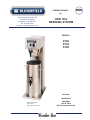
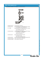
OWNERS MANUAL
for
ICED TEA
BREWING SYSTEM
MODELS:
8740
8742
8748
Includes:
Installation
Operation
Use & Care
Servicing Instructions
Model 8748 Brewer
with optional
8602 Iced Tea Dispenser
606
2060 Cessna Dr, Suite 100
Vacaville, CA 95688
telephone: 707-448-5151
fax: 707-448-1521
www.bloomfieldworldwide.com

NOTE: For your protection, please note that equipment in
this shipment was carefully inspected and packaged by skilled
personnel before leaving the factory.
Upon acceptance of this shipment, the transportation
company assumes full responsibility for its safe delivery.
IF SHIPMENT ARRIVES DAMAGED:
1. VISIBLE LOSS OR DAMAGE: Be certain that any
visible loss or damage is noted on the freight bill
or express receipt, and that the note of loss or damage
is signed by the delivery person.
2. FILE CLAIM FOR DAMAGE IMMEDIATELY:
Regardless of the extent of the damage.
3. CONCEALED LOSS OR DAMAGE: if damage is
unnoticed until the merchandise is unpacked, notify the
transportation company or carrier immediately, and
¿OH³&21&($/(''$0$*(´FODLPZLWKWKHP This
PXVWEHGRQHZLWKLQ¿IWHHQGD\VIURPWKHGDWH
the delivery was made to you. Be sure to retain the
container for inspection.
%ORRP¿HOGFDQQRWDVVXPHOLDELOLW\IRUGDPDJHRUORVV
incurred in transit. We will, however, at your request, supply
you with the necessary documents to support your claim.
WARRANTY STATEMENT
SERVICE POLICY AND PROCEDURE GUIDE
ADDITIONAL WARRANTY EXCLUSIONS
yp ,p qp
g
NOT
NOT
E:
E:
Fo
Fo
ry
r y
y
our
our
pr
pr
p
ote
ote
cti
cti
on
on,
,
pl
pl
p
eas
eas
en
e n
ote
ote
th
th
at
at
equ
equ
q
ipm
ipm
p
ent
ent
in
in
3
3
.
CON
CON
CEA
CEA
LED
LED
LO
LO
SS
SS
OR
OR
DAM
DAM
AGE
AGE
:
:
if
if
dam
dam
age
age
g
is
is
SHIPPING DAMAGE CLAIMS PROCEDURE
1. Resetting of safety thermostats, circuit breakers,
overload protectors, or fuse replacements.
2. All problems due to operation at voltages other than
VSHFL¿HGRQHTXLSPHQWQDPHSODWHVFRQYHUVLRQWR
correct voltage must be the customer’s responsibility.
3. All problems due to electrical connections not made in
accordance with electrical code requirements and
wiring diagrams supplied with the equipment.
4. Replacement of items subject to normal wear, to
include such items as knobs and light bulbs. Normal
maintenance functions including adjustment of
thermostats, microswitches, and replacement of fuses
and indicating lights are not covered under warranty.
All problems due to inadequate water supply, such as
ÀXFWXDWLQJRUKLJKRUORZZDWHUSUHVVXUH
6. All problems due to mineral/calcium deposits, or
FRQWDPLQDWLRQIURPFKORULGHVFKORULQHV'HOLPLQJLV
considered a preventative maintenance function and is
not covered by warranty.
All electrical equipment manufactured by BLOOMFIELD is
warranted against defects in materials and workmanship
for a period of (1 year labor, two year parts) from the date
RIRULJLQDOLQVWDOODWLRQDQGLVIRUWKHEHQH¿WRIWKHRULJLQDO
purchaser, except that:
a. airpots carry a 30 day parts warranty only.
b. dispensers; i.e., tea and coffee carry a 90 days parts
warranty only, excludes decanters.
c. decanters are not covered by this warranty
THE FOREGOING OBLIGATION IS EXPRESSLY GIVEN
IN LIEU OF ANY OTHER WARRANTIES, EXPRESSED
OR IMPLIED, INCLUDING ANY IMPLIED WARRANTY OF
MERCHANTABILITY OR FITNESS FOR A PARTICULAR
PURPOSE, WHICH ARE HEREBY EXCLUDED.
BLOOMFIELD, LLC SHALL NOT BE LIABLE FOR
INDIRECT, INCIDENTAL OR CONSEQUENTIAL DAMAGES
OR LOSSES FROM ANY CAUSE WHATSOEVER.
This warranty is void if it is determined that upon inspection
by an authorized service agency that the equipment has
EHHQPRGL¿HGPLVXVHGPLVDSSOLHGLPSURSHUO\LQVWDOOHGRU
GDPDJHGLQWUDQVLWRUE\¿UHÀRRGRUDFWRI*RG
It also does not apply if the serial nameplate has been
removed or unauthorized service personnel perform service.
7KHSULFHVFKDUJHGE\%ORRP¿HOGIRULWVSURGXFWVDUHEDVHG
upon the limitations in this warranty. Seller’s obligation under
this warranty is limited to the repair of defects without charge
E\D%ORRP¿HOG Authorized Service Agency or one of its
VXEDJHQFLHV This service will be provided on customer’s
SUHPLVHVIRUQRQSRUWDEOHPRGHOV3RUWDEOHPRGHOVDGHYLFH
ZLWKDFRUGDQGSOXJRWDGLVSHQVHUPXVWEHWDNHQRUVKLSSHG
to the closest authorized service agency, transportation
charges prepaid, for services.
In addition to restrictions contained in this warrantyVSHFL¿F
OLPLWDWLRQVDUHVKRZQEHORZ$GGLWLRQDOWDUUDQW\([FOXVLRQV
%ORRP¿HOG Authorized Service Agencies are located in
principal cities.
This warranty is valid in the United States, Canada and void
HOVHZKHUH3OHDVHFRQVXOW\RXUFODVVL¿HGWHOHSKRQHGLUHFWRU\
or your food service equipment dealer; or, for information and
other details concerning warranty, write to:
7. Full use, care and manuals may or may not be sent with
each unit, only a condensed version. Please visit our
web site to download the full version.
8. TUDYHOPLOHDJHLVOLPLWHGWR¿IW\PLOHVIURPDQ
DXWKRUL]HGVHUYLFHDJHQF\RURQHRILWVVXEVHUYLFH
agencies.
9. All labor shall be performed during normal working hours.
Overtime premium shall be charged to the customer.
10. $OOJHQXLQH%ORRP¿HOGUHSODFHPHQWSDUWVDUHZDUUDQWHG
IRUQLQHW\GD\VIURPGDWHRISXUFKDVHRQQRQ
warranted equipment. Any use of non-genuine
%ORRP¿HOGSDUWVFRPSOHWHO\YRLGVDQ\ZDUUDQWy.
11. Installation, labor and job checkouts are not considered
warranty.
12. Charges incurred by delays, waiting time or operating
restrictions that hinder the service technicians ability
to perform services are not covered by warranty.
This includes institutional and correctional facilities.
xi
606 Owners Manual for 8742-8748 Tea Brewer 2M-76116
PARTS TOWN
1200 Greenbriar Dr,
Addison, IL 60101
Phone: (800) 438-8898 Fax: (888) 513-0259
FXVWRPHUVHUYLFH#SDUWVWRZQFRPZZZEORRP¿HOGZRUOGZLGHFRP

1
TABLE OF CONTENTS
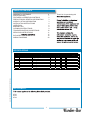
SPECIFICATIONS
Thank You for purchasing this
WARRANTY STATEMENT xi
1 SNOITACIFICEPS
FEATURES & OPERATING CONTROLS 2
PRECAUTIONS & GENERAL INFORMATION 3
AGENCY LISTING INFORMATION 3
INSTALLATION INSTRUCTIONS 4
6 NOITAREPO
8 AET GNIWERB
CLEANING INSTRUCTIONS 9
TROUBLESHOOTING SUGGESTIONS 10
SERVICING INSTRUCTIONS 11
15
EXPLODED VIEW & PARTS LIST 16
02 SMARGAID GNIRIW
APPLICABILITY
8740
8742
8748
61167-M2rewerBaeT8478-2478roflaunaMsrenwO606
Country Model Style Volts Amps Wa�s Power Supply Cord
USA 4F-8740-3/5G-120V 3-gal, 5-gal Iced Tea Brewer 120 13 1515 NEMA 5-15P
USA 4F-8742-3G-120V 3-gal Iced Tea Brewer 120 12.5 1515 NEMA 5-15P
USA 4F-8748-5G-120V 5-gal Iced Tea Brewer 120 13 1500 NEMA 5-15P
CAN 4F-8748-5G-120C 5-gal Iced Tea Brewer 120 13 1500 NEMA 5-20P

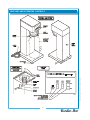
FEATURES AND OPERATING CONTROLS
2
IL1673
606 Owners Manual for 8742-8748 Tea Brewer 2M-76116

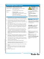
PRECAUTIONS AND GENERAL INFORMATION
WARNING: ELECTRIC SHOCK HAZARD
service personnel. Do not open any access panels which require the use of tools. Failure
to heed this warning can result in electrical shock.
WARNING: INJURY HAZARD
all applicable electrical and plumbing codes. Failure could result in property damage and
personal injury.
WARNING: ELECTRIC SHOCK HAZARD
Brewer must be properly grounded to prevent possible shock hazard. DO NOT assume a
plumbing line will provide such a ground. Electrical shock will cause death or serious Injury.
WARNING: BURN HAZARD
This appliance dispenses very hot liquid. Serious bodily injury from scalding can occur from
contact with dispensed liquids.
This appliance is intended for commercial use only.
This appliance is intended for use to brew beverage products for
human consumption. No other use is recommended or
authorized by the manufacturer or its agents.
This appliance is intended for use in commercial establishments,
where all operators are familiar with the appliance use,
limitations and associated hazards. Operating instructions and
warnings must be read and understood by all operators and
users.
Except as noted, this piece of equipment is made in the USA
and has American sizes on hardware. All metric conversions are
approximate and can vary in size.
The following trouble shooting, component views and parts lists
are included for general reference, and are intended for use by
This manual should be considered a permanent part of this
appliance. The manual must remain with the appliance if it is
sold or moved to another location.
CAUTION:
EQUIPMENT DAMAGE
DO NOT plug in or energize this
appliance until all Installation
Instructions are read and followed.
Damage to the Brewer will occur if
these instructions are not followed.
CAUTION:
BURN HAZARD
Exposed surfaces of the
appliance, brew chamber and
decanter may be HOT to the
touch, and can cause serious
burns.
AGENCY APPROVAL INFORMATION
C
B
C
B
E d
C
E
p
C
E
DO NO
T
p
W
s
t
WARNING
W
a
p
WARNING
W
B
p
W
WARNING
W
T
c
W
W
WARNING
These brewers are listed under ETL 3016449.
This brewer meets
Standard 4 only when installed,
operated and maintained in accordance with the enclosed
instructions.
STD 4
STD 4
3

INSTALLATION
4
READ THIS CAREFULLY BEFORE STARTING THE INSTALLATION
Unpack the unit. Inspect all components for completeness and
condition. Ensure that all packing materials have been removed
from the unit.
Verify that the Spray Head Gasket and Spray Disk are properly
installed.
LEVELING THE UNIT
Verify that an adjustable leg is installed at each corner of the
brewer, and that a rubber foot is installed on each leg.
Set Brewer in its operating location. Level the Brewer. A spirit
level should be placed on the top of the unit, at the edge, as a
guide when making level adjustments.
Level the unit from left to right and front to back by turning the
adjustable feet. Be sure all four feet touch the counter to prevent
tipping.
PLUMBER’S INSTALLATION INSTRUCTIONS
Brewer must be connected to a POTABLE WATER, COLD
WATER line. Flush water line before connecting to Brewer.
DO NOT use a saddle valve with a self-piercing tap for the water
line connection. Such a tap can become restricted by waterline
debris. For systems that must use a saddle tap, shut off the
main water supply and drill a 3/16” (minimum) tap for the saddle
connection, in order to insure an ample water supply. Remember
WRÀXVKWKHOLQHSULRUWRLQVWDOOLQJWKHVDGGOH
The brewer must be installed on a water line with average
pressure between 20 PSI and 90 PSI. If your water pressure
exceeds 90 PSI at anytime, a pressure regulator must be
installed in the water supply line to limit the pressure to not more
than 90 PSI in order to avoid damage to lines and solenoid.
A water shut-off valve should be installed on the incoming water
line in a convenient location (Use a low restriction type valve,
VXFKDVDWXUQEDOOYDOYHWRDYRLGORVVRIZDWHUÀRZWKUXWKH
valve.
The provided water line strainer must be installed in the supply
line, between the shutofIYDOYHDQGLQOHW¿WWLQJ1RWH)/2:
arrow marking on strainer body.
IMPORTANT:
To enable the installer to make
a quality installation and to
minimize installation time, the
following suggestions and tests
should be done before the
actual unit installation is started:
CAUTION:
EQUIPMENT DAMAGE
DO NOT plug in or energize this
appliance until all Installation
Instructions are read and
followed. Damage to the
Brewer will occur if these
instructions are not followed.
CAUTION:
UNSTABLE
EQUIPMENT HAZARD
It is very important for safety
and for proper operation that the
brewer is level and stable when
VWDQGLQJLQLWV¿QDORSHUDWLQJ
position. Provided adjustable,
non-skid legs must be installed
at each corner of the unit.
Failure to do so will result in
movement of the brewer which
can cause personal Injury and/
or damage to brewer.
NOTE: :ater supply inlet line
must meet certain minimum
criteria to insure successful
operation of the brewer.
%ORRP¿HOGUHFRPPHQGV´
copper tubing for installation of
less than 12 feet and 3/8” for
more than 12 feet from a 1/2”
water supply line.
A
Q
C
A
EQ
CA
CA
UN
EQ
606 Owners Manual for 8742-8748 Tea Brewer 2M-76116

INSTALLATION (continued)
5
NOTE: This equipment must
be installed to comply with
applicable federal, state and
local plumbing codes and
ordinances.
WARNING:
SHOCK HAZARD
Brewer must be properly
grounded to prevent possible
shock hazard. DO NOT assume
a plumbing line will provide
such a ground. Electrical shock
will cause death or serious
injury.
IMPORTANT:
Supply power must match
nameplate for voltage and
phase. Connecting to the wrong
voltage will damage the brewer
or result in decreased perfor-
mance. Such damage is not
covered by warranty.
IMPORTANT: Do not connect
brewer to electrical power until
\RXDUHUHDG\WR¿OOWKHWDQN
See instructions at left.
IMPORTANT: The ground
prong of the plug is part of a
system designed to protect
you from electrical shock in the
event of internal damage. Nev-
er cut off the ground prong nor
WZLVWDEODGHWR¿WDQH[LVWLQJ
receptacle. Contact a licensed
electrician to install the proper
circuit and receptacle.
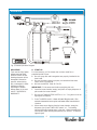
NSF requires that the brewer be able to be moved for cleaning
underneath. AÀH[OLQHRUORRSVRIFRSSHUWXELQJZLOOVDWLVI\WKLV
requirement. See Figure 2 below.
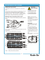
ELECTRICIAN’S INSTALLATION INSTRUCTIONS
REFER TO ELECTRICAL SPECIFICATIONS - Page 1
Check the nameplate to determine correct electrical service
required for the Brewer to be installed.
IMPORTANT: Before connecting to electricity, make sure
automatic brewers are connected to the water supply.
Models 8742 and 8748 are equipped with a cord and plug.
They require a 115 - 125 volt 20 amp circuit (50/60 Hz, 2 wire
plus ground, with NEMA 5-15R or 5-20R Receptacle).
W
SH
Br
ewer m
u
Fig. 2 Water Supply Installation
NEMA 5-15R
RECEPTACLE
NEMA 5-15P
PLUG
GROUND
PIN
61167-M2 rewerB aeT 8478-2478 rof launaM srenwO 606

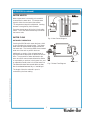
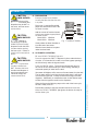
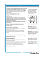
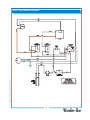
OPERATION
Fig. 3 Brewer Operation Diagram
START-UP
For initial start-up, or if the brewer has not been used for an
extended period of time:
Be sure spray disk and brew gasket are properly installed in the
brew head.
Be sure the water supply is properly connected and the water
supply valve is turned ON.
Be sure the WATER TANK IS FILLED.
IMPORTANT: Fill the water tank before energizing this unit:
1. Insert the brew chamber (empty) and place an empty dispenser in
place under the brew chamber.
2. Be sure the TANK HEATER SWITCH is “OFF”. Plug the unit into an
appropriate receptacle.
3. Press The BREW switch. WDWHUZLOOVWDUW¿OOLQJWKHWDQN5XQ
VHYHUDOFRQVHFXWLYHEUHZF\FOHVXQWLOZDWHUÀRZVIURPWKHEUHZ
chamber.
4. When water stops dripping from the brew chamber, empty the
dispenser, then press TANK HEAT switch “ON”. The heating
element will begin heating water in the tank. When the water has
reached the proper brewing temperature, the “READY TO BREW”
light will glow.
A.
IMPORTANT:
Tank must be full of water
before pressing TANK
HEATER SWITCH “ON”.
Heating elements will be
damaged if allowed to
operate without being
fully submerged in water.
Damage caused by
operating the brewer
without water in the tank
is NOT COVERED BY
WARRANTY.
6
606 Owners Manual for 8742-8748 Tea Brewer 2M-76116

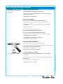
OPERATION (continued)
WATER HEATER
Water temperature is sensed by a thermobulb
inserted into the water tank. This temperature
signal is fed to the mechanical thermostat.
The temperature setpoint is adjustable. Heating
element is energized by the thermostat.
Excessive temperature will trip the hi-limit safety
switch. The hi-limit will automatically reset when
the brewer cools.
WATER FLOW
AUTOMATIC OPERATION
Pressing the BREW switch starts the timer, which
in turn energizes the solenoid valve. This allows
ZDWHUIURPDQH[WHUQDOZDWHUVXSSO\WRÀRZLQWR
the water tank. The incoming water forces heated
water out of the tank to perform the brew.
Additionally, a portion of the unheated water is
bypassed into the dispenser to dilute and cool the
brew. The proportion of water delivered to the
brew versus the amount water diverted to dilution
is controlled by a restrictor in the bypass line, and
an adjustable needle valve in the brew water line.
7KHVROHQRLGXVHVDÀRZFRQWUROGHYLFHVRWKDW
ÀRZLVFRQVLVWHQWEHWZHHQSVLDQGSVL
The length of time the solenoid is open is
controlled by the timer setting.
Fig. 5 Water Flow Diagram
Fig. 4 Heat Control Diagram
7
IL1675
61167-M2 rewerB aeT 8478-2478 rof launaM srenwO 606

BREWING TEA
8
A. PREPARATION
Examine the tea brew chamber
to verify that the short the wire rack
is in place.
3ODFHRQHJHQXLQH%ORRP¿HOG
SDSHU¿OWHULQWRWKHZLUHUDFNLQWKH
tea brew chamber.
$GGDQDPRXQWRIIUHVKWHDOHDYHV
to the brew chamber appropriate to
the brew volume.
0RGHO*DOORQV
0RGHO*DOORQV
*HQWO\VKDNHWKHEUHZFKDPEHUWR
OHYHOWKHEHGRIWHDOHDYHV
6OLGHWKHEUHZFKDPEHULQWRSODFH
XQGHUWKHEUHZKHDG
B. AUTOMATIC OPERATION
BE sure “READY TO BREW” light is lit.
Place the appropriate EMPTYGLVSHQVHULQSODFHXQGHUWKHEUHZ
chamber,IDEUHZWKUXOLGLVXVHGEHVXUHWKHE\SDVVRSHQLQJLQ
WKHOLGLVGLUHFWO\XQGHUWKHE\SDVVQR]]OH
Press the “BREW” switch. 7KHWHDEUHZVROHQRLGZLOORSHQIRU
DQDPRXQWRIWLPHGHWHUPLQHGE\WKHWLPHUVHWWLQJDGPLWWLQJD
PHDVXUHGTXDQWLW\RIZDWHULQWRWKHWDQN
,QOHWZDWHUZLOOGLVSODFHDOLNHDPRXQWRIKHDWHGZDWHUIURPWKHWDQN
7KHKRWZDWHUZLOOEHIRUFHGLQWRWKHEUHZKHDGZKHUHLWZLOOVSUD\
RYHUWKHEHGRIJURXQGV)UHVKO\EUHZHGWHDZLOOEHJLQWR¿OOWKH
GLVSHQVHr. $GGLWLRQDOOyDPHDVXUHGDPRXQWRIFROGGLOXWLRQZDWHU
ZLOOÀRZIURPWKHE\SDVVQR]]OHLQWRWKHGLVSHQVHr.
:KHQWKHÀRZDQGDOOGULSSLQJVWRSVDWWKHHQGRIWKHEUHZF\FOH
WKHWHDLVUHDG\WRVHUYH
'LVFDUGWKHFRQWHQWVRIWKHEUHZFKDPEHUDQGULQVHLWLQDVLQN
When the ”READY T2%5(:´OLJKWJORZVWKHEUHZHULVUHDG\IRU
another brew cycle.
CAUTION:
BURN HAZARD
([SRVHGVXUIDFHVRIWKH
brewerEUHZFKDPEHUDQG
GLVSHQVHUPD\EH+2T to
WKHWRXFKDQGFDQFDXVH
serious burns.
CAUTION:
BURN HAZARD
TRDYRLGVSODVKLQJRU
RYHUÀRZLQJKRWOLTXLGV
ALWAYS place an empty
GLVSHQVHUXQGHUWKHEUHZ
chamber before starting
WKHEUHZF\FOH)DLOXUHWR
comply can cause serious
burns.
CAUTION:
BURN HAZARD
$IWHUDEUHZF\FOHEUHZ
chamber contents are
+2T. Remove the brew
FKDPEHUDQGGLVSRVHRI
XVHGJURXQGVZLWKFDUH
)DLOXUHWRFRPSO\FDQ
cause serious burns.
(
CA
CA
B
U
([
SR
VH
G
V
C
A
B
U
LG
T
C
A
BU
$IW E
Fig. 7 Tea Brew Chamber
,/
606 Owners Manual for 8742-8748 Tea Brewer 2M-76116

CLEANING INSTRUCTIONS
PROCEDURE: Clean Tea Brewer
PRECAUTIONS: Disconnect brewer from electric power.
Allow brewer to cool.
FREQUENCY: Daily
TOOLS: Mild Detergent, Clean Soft Cloth or Sponge
Bristle Brush, Bottle Brush
1. Disconnect brewer from electric power.
Allow brewer to cool before cleaning.
2. Remove dispenser.
3. Remove and empty brew chamber.
4. 5HPRYHWKHVSUD\GLVNIURPWKHEUHZKHDG6HH¿JXUH
Press up on the spray disk ears, then turn the disk to the left
to unlatch. Remove the gasket from inside the brew head.
5. Wipe inside of brew head and area around the brew head
with a soft clean cloth or sponge moistened with clean water.
6. Wash the spray disk in a sink using warm water and a mild
detergent. A bristle brush may be used to clear clogged
spray holes. Rinse the spray disk with clean water and allow
to air dry.
7. Wash the brew chamber in a sink using warm water and a
mild detergent. A bristle brush may be used to clean the
inside. Rinse with clean water and allow to air dry.
Wipe the exterior of the brewer with a soft clean cloth or
sponge moistened with clean water.
10. Reinstall the gasket INSIDE the brew head, then reinstall the
spray disk.
11. Be sure the wire rack is in place in the brew chamber, then
reinstall the brew chamber.
12. &OHDQGLVSHQVHUVE\¿OOLQJZLWKZDUPVRDS\ water. Empty
and rinse with clean water. Wipe the exterior with a soft
clean cloth or sponge moistened with clean water. Invert and
allow to air dry.
Procedure is complete
CAUTION:
BURN HAZARD
Brewing and serving
temperatures of tea are
extremely hot.
Hot tea will cause serious skin
burns.
CAUTION:
SHOCK HAZARD
Do not submerge or immerse
brewer in water.
IMPORTANT:
DO NOT use steel wool, sharp
objects, or caustic, abrasive or
chlorinated cleansers to clean
the brewer or dispensers.
A
A
U
d
CA
CA
BU
Brewing an
d
CA
SH
Dtb
Fig. 8 Cleaning
9
IL1677
61167-M2 rewerB aeT 8478-2478 rof launaM srenwO 606

TROUBLESHOOTING SUGGESTIONS
10
606 Owners Manual for 8742-8748 Tea Brewer 2M-76116
SYMPTOM POSSIBLE CAUSE SUGGESTED REMEDY
Water won’t heat
Brewer unplugged or circuit breaker
tripped
Check power supply cord
Check / reset circuit breaker
Temperature setpoint too low Set for desired temperature
Hi-Limit safety switch tripped Allow to cool hi-limit will self-reset
Damaged internal component or wiring
Examine wiring & connectors, controller, power
board and heating element, Repair/replace as
needed
Tea level too high or low Timer out of adjustment Adjust timer
%UHZFKDPEHURYHUÀRZV
TRRPDQ\¿OWHUSDSHUVRUZURQJ¿OWHU
paper
8VHRQHJHQXLQH%ORRP¿HOG¿OWHUSHUEUHZ
Brew chamber dispense hole plugged Thoroughly clean brew chamber
Too much tea leaves Use correct amount of tea
Sprays water from brew
head
Spray gasket improperly installed Check/reinstall gasket on INSIDE of brew head
No brew
Spray disk plugged Clean spray disk
Damaged internal component or wiring
Check switches, timer and solenoid. Repair,
replace as needed
Water supply OFF Turn water supply ON
“Y” Strainer or solenoid inlet strainer
plugged
Clean strainer
WDWHU¿OWHULIXVHGSOXJJHG 5HSODFH¿OWHUHOHPHQW
Poor tea quality
.HHSEUHZHUDQGGLVSHQVHUFOHDQ,QVWDOODWDVWHDQGRGRU¿OWHULQZDWHUVXSSO\, and replace
cartridges regularly. Use a quality fresh supply of tea leaves. Use the amount of tea leaves
appropriate to brew volume. The needle valve adjusts the ratio of brew water to dilution
water6HWWKHQHHGOHYDOYHWRDGMXVWWKHVWUHQJWKRIWKH¿QDOEUHw.

SERVICING INSTRUCTIONS
CAUTION:
SHOCK HAZARD
Opening access panels on this
brew may expose uninsulated
electrical components.
Disconnect brewer from
electrical power before
removing any panel.
C
A
S
H
Opening acc
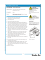
ACCESS PANELS
TOP PANEL:
Remove top panel to access hot water tank, thermostat, timer,
brew solenoid and brew circuit tubing.
Top panel is held by two screws at the rear and a retaining lip at
the front .
REAR PANEL:
Remove rear panel to access wiring and bypass nozzle tubing.
Rear panel is held by eight screws on the perimeter.
Fig. 8 Access Panels
11
IL1678
61167-M2 rewerB aeT 8478-2478 rof launaM srenwO 606

SERVICING INSTRUCTIONS (continued)
12
TEMPERATURE ADJUSTMENT
Unplug power cord or turn circuit breaker OFF. Remove top
panel.
Pull vent tube out of tank lid and insert a thermometer of known
accuracy in hole. Reconnect brewer to electrical power.
Place empty container under brew chamber. Energize brewer
and allow unit to heat. When the READY T2%5(:OLJKW¿UVW
glows, read the temperature displayed on thermometer.
Adjust thermostat by turning shaft; clockwise increases
temperature. 1/8 turn = approximately 10ºF, or 5.6ºC.
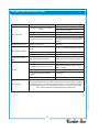
Refer to Table 1 below for proper brewing temperature based on
altitude.
Upon completion, remove thermometer and reinstall the vent line
and top panel.
Fig. 9 Checking and Adjusting Brew Temperature
CAUTION:
SHOCK HAZARD
These procedures involve
exposed electrical circuits.
These procedures are to
EHSHUIRUPHGE\TXDOL¿HG
technical personnel only.
NOTE: Optimum brewing
temperature is 195ºF to 205ºF
(90ºC to 96ºC).
Thermostat should be adjusted
to a maximum temperature of
200ºF (95ºC).
IMPORTANT:
A mechanical thermostat will
maintain temperature within
±5ºF.
To prevent boiling water in
the brewer, controller should
be adjusted to a maximum
temperature equal to the local
boiling temperature minus 5ºF,
or 200ºF (94ºC), whichever is
less.
NOTE: 1/8 turn = approximately
10ºF (5.6ºC).
C
A
S
H
Th
ese proc
e
Table 1 Boiling Temperature by Altitude
Fig. 10 Adjust Thermostat
606 Owners Manual for 8742-8748 Tea Brewer 2M-76116
IL1606
IL1607
IL1601
IL1602
TEMP. (°C)
ELEVATION (meters above sea level)
100
0
150
300
450
600
750
900
1,050
1,200
1,500
1,650
1,800
1,950
1,350
97
94
91
88

61167-M2 rewerB aeT 8478-2478 rof launaM srenwO 606
SERVICING INSTRUCTIONS (continued)
IMPORTANT: Water pressure
must be between 20 p.s.i and
SVLÀRZLQJSUHVVXUH
If water pressure exceeds this
YDOXHRULIZDWHUSUHVVXUH
YDULHVJUHDWOy, a pressure
UHJXODWRUPXVWEHLQVWDOOHGLQ
the water supply line.
IMPORTANT: %HIRUHVHW
WLQJDVVHPEO\LQWRWDQNPDNH
VXUHWDQNOLGJDVNHWLVSURSHUO\
VHDWHGRQÀDQJHRIOLG
IMPORTANT: :KHQPRXQWLQJ
WKHUPRVWDWEHVXUHDQHZVHDO
ZDVKHULVSODFHGEHORZWKH
¿WWLQJRQWKHFDSLOODU\OLQH
3XVKVHQVLQJEXOEWKUXWDQNOLG
XQWLO¿WWLQJVHDWV
,IUHSODFLQJJUD\ERGLHGWKHUPR
ZLWKSQEHVXUHWR
UHPRYHWXEHIURPWKHUPRZHOO
TLJKWHQFDSLOODU\ORFNQXWRQO\
HQRXJKWRHQVXUHQRZDWHU
OHDNDJH([FHVVLYHWLJKWHQLQJ
LVQRWQHFHVVDUy.
SOLENOID TIME ADJUSTMENT
7KHDPRXQWRIZDWHUGLVSHQVHGDXWRPDWLFDOO\GXULQJDEUHZF\FOH
LVFRQWUROOHGE\WKH62/(12,' 7,0(VHFWLRQRIWKHFRQWUROOHr.
Place empty dispenser under brew chamber3UHVVWKH%5(:
VZLWFK,QFOXGLQJERWKEUHZZDWHUDQGGLOXWLRQZDWHr, brewer
VKRXOGGLVSHQVH
AWRWDORIJDOORQV0RGHORIZDWHURr,
AWRWDORIJDOORQV0RGHORIZDWHr.
TRDGMXVW
5HPRYHWRSSDQHO
TRWDOGHOLYHUHGYROXPHLVGHSHQGDQWXSRQWKHWRWDOWLPHWKH
VROHQRLGLVHQHUJL]HG $GMXVWWLPHUFORFNZLVHLQFUHDVHVWLPH
FRXQWHUFORFNZLVHGHFUHDVHVWLPH5XQVHYHUDOF\FOHVWRFKHFN
WRWDODPRXQWRIZDWHUGHOLYHUHG
$GMXVWGLOXWLRQ TXUQQHHGOHYDOYHDOOWKHZD\LQFORVHGWKHQ
RSHQWXUQV
%UHZVHYHUDOEDWFKHVRIWHDWRFKHFNIRUSURSHUFRQFHQWUDWLRQ
DQGWDVWH5HDGMXVWQHHGOHYDOYHDQGWLPHUDVUHTXLUHG
5HLQVWDOOWRSSDQHO
REMOVE TANK COVER ASSEMBLY
8QSOXJEUHZHURUWXUQFLUFXLWEUHDNHUOFF. Turn OFF water
supply5HPRYHWRSSDQHO
'LVFRQQHFWEUHZ¿OODQGRXWOHWWXEHVIURPWDQNOLG¿WWLQJV
'LVFRQQHFWDOOZLULQJIURPWKHUPRVWDWKLOLPLWDQGKHDWLQJ
element.
/RRVHQFHQWHUVFUHZRQWDQNKROGGRZQEUDFNHW5HPRYH
KROGGRZQEUDFNHWE\VOLGLQJVKRUWVORWWHGHQGRfIRIORFNLQJVWXG
DQGOLIWLQJLWRIf. 5HPRYHFRYHUDVVHPEO\E\OLIWLQJLWVWUDLJKWXS
5HDVVHPEOHLQUHYHUVHRUGHr.
REPLACE THERMOSTAT
8QSOXJEUHZHURUWXUQFLUFXLWEUHDNHUOFF. Turn OFF water
supply5HPRYHWRSSDQHO
'LVFRQQHFWDOOZLULQJIURPWKHUPRVWDWRQOy/RRVHQDQGIUHHMDP
QXWIURPSDVVWKUX¿WWLQJVHFXULQJWHPSHUDWXUHVHQVLQJEXOE
5HPRYHWZRVFUHZVKROGLQJWKHUPRVWDWWREUDFNHW
/LIWRXWWKHUPRVWDWVHQVLQJEXOEDQGWKHUPRVWDWJDVNHW
5HDVVHPEOHLQUHYHUVHRUGHr.
Fig. 11 Adjust Solenoid Time
IL1679

SERVICING INSTRUCTIONS (continued)
REPLACE HEATING ELEMENT
Remove tank cover assembly (see page 13).
Remove two hex nuts holding element to cover. Pull element
from mounting holes.
Reassemble in reverse order.
REPLACE SOLENOID
Symptom: $XWRPDWLFEUHZHUZLOOQRWÀRZZDWHURr,
automatic brewer drips continuously from brew head.
Unplug power cord or turn circuit breaker OFF. Turn water
supply OFF.
Remove top panel.
Disconnect wiring from solenoid.
Unscrew water inlet piping from solenoid.
Remove two screws holding solenoid to bracket.
Remove brew and dilution manifold from solenoid, transfer
components to new solenoid
Transfer solenoid bracket to new solenoid.
Reassemble in reverse order.
REPLACE TIMER ASSEMBLY
Unplug power cord or turn circuit breaker OFF.
Remove top panel. Remove knob and three screws holding timer
to bracket. Disconnect wiring to timer.
Reassemble in reverse order.
Adjust timer as described on page 13
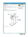
CLEAN STRAINER SCREEN
Unplug power cord or turn circuit breaker OFF. Turn water
supply OFF.
Remove bottom cap from strainer:LWKGUDZ¿OWHUVFUHHQIURP
strainer body.
Clean screen with a suitable brush.
Reassemble in reverse order.
IMPORTANT: When replacing
heating element, also replace
seal gaskets.
14
Fig. 12 Water Line Strainer
IL1680
606 Owners Manual for 8742-8748 Tea Brewer 2M-76116

SERVICING INSTRUCTIONS (continued)
15
CAUTION:
CHEMICAL BURN
HAZARD
Deliming chemicals are caustic.
Wear appropriate protective
gloves and goggles during this
procedure.
Never siphon deliming
chemicals or solutions by
mouth.
This operation should only be
SHUIRUPHGE\TXDOL¿HGDQG
experienced service personnel.
IMPORTANT: DO NOT spill,
splash or pour water or deliming
solution into or over any internal
component other than the inside
of the water tank.
IMPORTANT: DO NOT allow
any internal components to
come into contact with the
deliming solution. Take care to
keep all internal components
dry.
NOTE: Repeat steps 4 thru 5
as required to remove all scale
and lime build-up.
NOTE: Normally, silicone
hoses do not need to be
delimed. Should deliming hoses
become necessary%ORRP¿HOG
recommends replacing the
hoses.
PROCEDURE: Delime the Water Tank
PRECAUTIONS: Disconnect brewer from electric power.
Allow brewer to cool.
FREQUENCY: As required (Brewer slow to heat)
TOOLS: Deliming Solution
Protective Gloves, Goggles & Apron
Mild Detergent, Clean Soft Cloth or Sponge
Bristle Brush, Bottle Brush
Large Sink (or other appropriate work area)
1. Unplug power cord. Turn off the water shut-off valve and
GLVFRQQHFWWKHZDWHUVXSSO\OLQHIURPWKHEUHZHULQOHW¿WWLQJ
2. Remove the tank cover assembly as described on page 13.
3. Remove the water tank from the brewer body by lifting
straight up. Empty all water from the tank. Set the tank back
into the brewer.
4. Mix 2 quarts of deliming solution according to the manufac-
turer’s directions. Carefully pour the deliming solution into
the water tank. Lower the lid assembly back onto the tank.
Allow to sit for 30 minutes, or as directed by the manufac-
turer.
5. At end of soaking period, remove lid assembly from tank.
Thoroughly rinse internal components of lid assembly with
clear water. Using a stiff bristle brush, scrub the heating
element and faucet water coil to remove lime and calcium
build-up. Rinse with clean water. Store the lid assembly in a
safe location.
6. Remove the tank from the brewer and empty. Using a stiff
bristle brush, scrub the interior of the water tank to remove
lime and calcium build-up. Rinse with clean water.
7. Set the tank back into the brewer. Reassemble the tank lid
to the water tank. Make sure the gasket is properly in place,
and then reinstall lid clamps.
8. Reinstall wiring to heating element and thermostat.
Reassemble piping for the faucet. Verify that all internal com-
ponents are dry, and then reinstall the top panel.
9. Reconnect brewer to electrical supply and reconnect water
supply.
11. ,QVWDOOWKHEUHZFKDPEHUZLWKRXW¿OWHUSDSHURUJURXQGV
Run at least three full brew cycles and discard all water
generated.
12. Brewer is ready to use.
CA
CA
CH
HA
Delimin
g
c
h
61167-M2 rewerB aeT 8478-2478 rof launaM srenwO 606

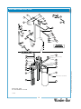
EXPLODED VIEW: 8742 - 8748
16
Model: 8742, 8748
ICE TEA BREWING SYSTEM
PL606
46
29
Purchase Locally
Tube, Silicone 1”, (see above)
31
32
33
34
35
37
38
39
40
41
42
43
44
45
1
2
3
7
8
9
10
11
12
13
14
15
16
17
18
19
20
22
21
28
27
23
24
25
26
4
5
6
606 Owners Manual for 8742-8748 Tea Brewer 2M-76116

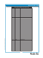
PARTS LIST: 8742 - 8748
8742 & 8748 PLUMBING & HOT WATER TANK
Fig No Part No Description
1 2V-70102 TUBE VENT
2 2K-70421 FTG NYLON Y 3/16
3 2V-70398 TUBE VENT LONG
4 2K-70479 FTG MALE HOSE BARB
5 A6-73537 TUBE SIL .312 ID X 9 LG
6 2K-76687 FTG 1/4 SWIVEL FF X 3/8
7 2V-70352 VALVE NEEDLE SEAT
8 2K-70478 FTG PIPE TEE
9 2K-70476 FTG REDUCER 1/4X1/8FPT
10 2V-70124 VALVE SOLENOID 120V
11 2E-70477 CONNECTOR 1/47 MALE FLARE
12 2V-70424 TUBE ASSY VALVE INLET
13 F4-70422 TUBE SIL .312 ID X 1
14 2V-70131 TUBE OUTLET WATER 4 3/4L
15 2K-70130 ELBOW SPRAYER
16 A6-70163 RETAINER HEAD SPRAY
17 2I-70139 GASKET SPRAY HEAD
18 F4-70140 DISC SPRAYER STD.
19 2K-70154 FTG-UNION 1/4X1/4
20 2C-70155 NUT 7/16-20 HEX HD BRASS
21 2V-70111 TUBE FORMED INLET ASSY
22 2V-73027 STRAINER “Y” PLASTIC W/FT
23 2V-70102 TUBE VENT
24 2K-70429 FTG NYLON Y 1/4X3/16
25 F4-70426 TUBE SIL .25 ID X 1.5 LG
26 2C-70414 WASHER RESTRICTOR
27 F4-70430 TUBE SIL .25 ID X 12 LG
28 F4-70423 SPOUT WATER ASSY
29 2C-73457 NUT 8-32 HEX HEAD KEPS MS
31 2C-70134 STRAP HOLD DOWN ASSY
32 F4-70420 ELBOW OUTLET ASSY
33 2I-70152 GASKET ELEM HTG
34 F4-70409 WASHER BEVELLED
35 2C-70410 NUT 1/2-22HEX HD BRS/BRIT
37 F4-70415 TANK ASSY TEA BREWER 3 & 5 G
38 2N-70143UL ELEM HEATING 120V 1500W
39 2I-70152 GASKET ELEM HTG
40 2T-47499 THERMO HI LIMIT 120/240V
41 2I-70147 GASKET TANK COVER
42 F4-70516 COVER WELDED TANK ASSY TE
43 2I-72390 GROMMET .375 ID TRANSLUCE
44 WS-8512-51 THERMO CONTROL BREWERS
45 WS-86280 T-STAT COTHERM SUBST 851
46 2V-73034 TUBE FILL 90DEG BEND L=13
17
61167-M2 rewerB aeT 8478-2478 rof launaM srenwO 606

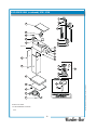
EXPLODED VIEW (continued): 8742 - 8748
18
Model: 8742, 8748
ICE TEA BREWING SYSTEM
PL606
1
2
3
4
5
6
7
16
17
18
19
20
10
9
11 8
12
13
14
15
21
22
23
24
25
26
27
Basin Assy
28
29
30
31
32
606 Owners Manual for 8742-8748 Tea Brewer 2M-76116
La page est en cours de chargement...
La page est en cours de chargement...
La page est en cours de chargement...
La page est en cours de chargement...
-
 1
1
-
 2
2
-
 3
3
-
 4
4
-
 5
5
-
 6
6
-
 7
7
-
 8
8
-
 9
9
-
 10
10
-
 11
11
-
 12
12
-
 13
13
-
 14
14
-
 15
15
-
 16
16
-
 17
17
-
 18
18
-
 19
19
-
 20
20
-
 21
21
-
 22
22
-
 23
23
-
 24
24


Bloomfield 8740-3/5G Le manuel du propriétaire
- Catégorie
- Cafetières
- Taper
- Le manuel du propriétaire
- Ce manuel convient également à
dans d''autres langues
- English: Bloomfield 8740-3/5G Owner's manual
Documents connexes
Autres documents
-
Waring WCM60PT Manuel utilisateur
-
GE G7CDABSSPSS Le manuel du propriétaire
-
-
GEAppliances PFE28RSH Technical Service Manual
-
GE Cafe Series CFE28UELDS Le manuel du propriétaire
-
GE Profile PFD28KSLSS Le manuel du propriétaire
-
 Prime-Line HR 14000 Mode d'emploi
-
 Doyon DP9 Manuel utilisateur

