Bloomfield EBC™ 2 Warmer Brewer Le manuel du propriétaire
- Catégorie
- Cafetières
- Taper
- Le manuel du propriétaire
Ce manuel convient également à

641
Includes:
Installation
Use & Care
Servicing Instructions
2060 Cessna Dr, Suite 100
Vacaville, CA 95688
telephone: 707-448-5151
fax: 707-448-1521
www.bloomfieldworldwide.com
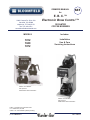
OWNERS MANUAL
for
E. B. C.™
Electronic Brew Control ™
DECANTER
COFFEE BREWERS
p/n 2M-75844 Rev J 146M 190613
E.B.C.™ brewers are protected under
U. S. Patent # 5,704,275
Other U. S. and Canadian patents pending.
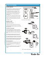
Models 1012 Brewer
with optional
8900-Series Glass Decanters
Model 1072 Brewer
with optional
8900-Series Glass Decanters
MODELS
1012
1040
1072

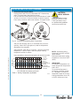
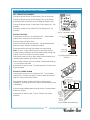
NOTE: For your protection, please note that equipment in
this shipment was carefully inspected and packaged by skilled
personnel before leaving the factory.
Upon acceptance of this shipment, the transportation
company assumes full responsibility for its safe delivery.
IF SHIPMENT ARRIVES DAMAGED:
1. VISIBLE LOSS OR DAMAGE: Be certain that any
visible loss or damage is noted on the freight bill
or express receipt, and that the note of loss or damage
is signed by the delivery person.
2. FILE CLAIM FOR DAMAGE IMMEDIATELY:
Regardless of the extent of the damage.
3. CONCEALED LOSS OR DAMAGE: if damage is
unnoticed until the merchandise is unpacked, notify the
transportation company or carrier immediately, and
¿OH³&21&($/(''$0$*(´FODLPZLWKWKHP This
PXVWEHGRQHZLWKLQ¿IWHHQGD\VIURPWKHGDWH
the delivery was made to you. Be sure to retain the
container for inspection.
%ORRP¿HOGFDQQRWDVVXPHOLDELOLW\IRUGDPDJHRUORVV
incurred in transit. We will, however, at your request, supply
you with the necessary documents to support your claim.
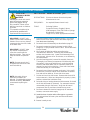
WARRANTY STATEMENT
SERVICE POLICY AND PROCEDURE GUIDE
ADDITIONAL WARRANTY EXCLUSIONS
yp ,p qp
g
N
O
TE: For
y
our
p
rotection
,
p
lease note that e
q
ui
p
ment in
3
.
CO
N
C
EALED L
OSS
O
R DAMA
G
E: i
f
dama
g
e is
SHIPPING DAMAGE CLAIMS PROCEDURE
1. Resetting of safety thermostats, circuit breakers,
overload protectors, or fuse replacements.
2. All problems due to operation at voltages other than
VSHFL¿HGRQHTXLSPHQWQDPHSODWHVFRQYHUVLRQWR
correct voltage must be the customer’s responsibility.
3. All problems due to electrical connections not made in
accordance with electrical code requirements and
wiring diagrams supplied with the equipment.
4. Replacement of items subject to normal wear, to
include such items as knobs and light bulbs. Normal
maintenance functions including adjustment of
thermostats, microswitches, and replacement of fuses
and indicating lights are not covered under warranty.
All problems due to inadequate water supply, such as
ÀXFWXDWLQJRUKLJKRUORZZDWHUSUHVVXUH
6. All problems due to mineral/calcium deposits, or
FRQWDPLQDWLRQIURPFKORULGHVFKORULQHV'HOLPLQJLV
considered a preventative maintenance function and is
not covered by warranty.
All electrical equipment manufactured by BLOOMFIELD is
warranted against defects in materials and workmanship
for a period of (1 year labor, two year parts) from the date
RIRULJLQDOLQVWDOODWLRQDQGLVIRUWKHEHQH¿WRIWKHRULJLQDO
purchaser, except that:
a. airpots carry a 30 day parts warranty only.
b. dispensers; i.e., tea and coffee carry a 90 days parts
warranty only, excludes decanters.
c. decanters are not covered by this warranty
THE FOREGOING OBLIGATION IS EXPRESSLY GIVEN
IN LIEU OF ANY OTHER WARRANTIES, EXPRESSED
OR IMPLIED, INCLUDING ANY IMPLIED WARRANTY OF
MERCHANTABILITY OR FITNESS FOR A PARTICULAR
PURPOSE, WHICH ARE HEREBY EXCLUDED.
BLOOMFIELD, LLC SHALL NOT BE LIABLE FOR
INDIRECT, INCIDENTAL OR CONSEQUENTIAL DAMAGES
OR LOSSES FROM ANY CAUSE WHATSOEVER.
This warranty is void if it is determined that upon inspection
by an authorized service agency that the equipment has
EHHQPRGL¿HGPLVXVHGPLVDSSOLHGLPSURSHUO\LQVWDOOHGRU
GDPDJHGLQWUDQVLWRUE\¿UHÀRRGRUDFWRI*RG
It also does not apply if the serial nameplate has been
removed or unauthorized service personnel perform service.
7KHSULFHVFKDUJHGE\%ORRP¿HOGIRULWVSURGXFWVDUHEDVHG
upon the limitations in this warranty. Seller’s obligation under
this warranty is limited to the repair of defects without charge
E\D%ORRP¿HOG Authorized Service Agency or one of its
VXEDJHQFLHV This service will be provided on customer’s
SUHPLVHVIRUQRQSRUWDEOHPRGHOV3RUWDEOHPRGHOVDGHYLFH
ZLWKDFRUGDQGSOXJRWDGLVSHQVHUPXVWEHWDNHQRUVKLSSHG
to the closest authorized service agency, transportation
charges prepaid, for services.
In addition to restrictions contained in this warrantyVSHFL¿F
OLPLWDWLRQVDUHVKRZQEHORZ$GGLWLRQDOWDUUDQW\([FOXVLRQV
%ORRP¿HOG Authorized Service Agencies are located in
principal cities.
This warranty is valid in the United States, Canada and void
HOVHZKHUH3OHDVHFRQVXOW\RXUFODVVL¿HGWHOHSKRQHGLUHFWRU\
or your food service equipment dealer; or, for information and
other details concerning warranty, write to:
7. Full use, care and manuals may or may not be sent with
each unit, only a condensed version. Please visit our
web site to download the full version.
8. TUDYHOPLOHDJHLVOLPLWHGWR¿IW\PLOHVIURPDQ
DXWKRUL]HGVHUYLFHDJHQF\RURQHRILWVVXEVHUYLFH
agencies.
9. All labor shall be performed during normal working hours.
Overtime premium shall be charged to the customer.
10. $OOJHQXLQH%ORRP¿HOGUHSODFHPHQWSDUWVDUHZDUUDQWHG
IRUQLQHW\GD\VIURPGDWHRISXUFKDVHRQQRQ
warranted equipment. Any use of non-genuine
%ORRP¿HOGSDUWVFRPSOHWHO\YRLGVDQ\ZDUUDQWy.
11. Installation, labor and job checkouts are not considered
warranty.
12. Charges incurred by delays, waiting time or operating
restrictions that hinder the service technicians ability
to perform services are not covered by warranty.
This includes institutional and correctional facilities.
xi
641 p/n 2M-75844 1012 1040 1072 Owmers Manual
PARTS TOWN
1200 Greenbriar Dr,
Addison, IL 60101
Phone: (800) 438-8898 Fax: (888) 513-0259
[email protected] / www.bloomfieldworldwide.com

TABLE OF CONTENTS
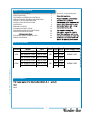
SPECIFICATIONS
Thank You for purchasing this
WARRANTY STATEMENT xi
SPECIFICATIONS 1
FEATURES & OPERATING CONTROLS 2
PRECAUTIONS & GENERAL INFORMATION 3
AGENCY LISTING INFORMATION 3
INSTALLATION INSTRUCTIONS 4
OPERATION 6
BREWING COFFEE 10
CLEANING INSTRUCTIONS 11
TROUBLESHOOTING SUGGESTIONS 12
SERVICING INSTRUCTIONS 14
20
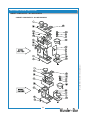
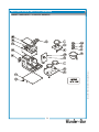
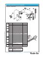
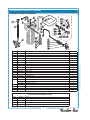
EXPLODED VIEWS & PARTS LISTS 22
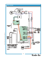
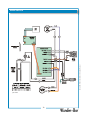
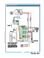
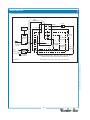
WIRING DIAGRAMS 29
APPLICABILITY
®
1012
1040
1072
1
641 p/n 2M-75844 1012 1040 1072 Owmers Manual
Country Model Style Volts Amps Was Power Supply Cord
4A-1012D3F-120V 3W In-Line 15 1800
4A-1040D2F-120V 2W In-Line 14.2 1700
4A-1072D3F-120V 3W Lo Profile 15 1800
4A-1012D3F-120C 3W In-Line 15 1800
4A-1040D2F-120C 2W In-Line 14.2 1700
4A-1072D3F-120C 3W Lo Profile 15 1800
USA
CAN
120
120
NEMA 5-15P
NEMA 5-20P

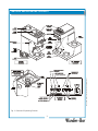
FEATURES AND OPERATING CONTROLS
Fig. 1 Features & Operating Controls
2
641 p/n 2M-75844 1012 1040 1072 Owmers Manual

PRECAUTIONS AND GENERAL INFORMATION
WARNING: ELECTRIC SHOCK HAZARD
service personnel. Do not open any access panels which require the use of tools. Failure
to heed this warning can result in electrical shock.
WARNING: INJURY HAZARD
all applicable electrical and plumbing codes. Failure could result in property damage and
personal injury.
WARNING: ELECTRIC SHOCK HAZARD
Brewer must be properly grounded to prevent possible shock hazard. DO NOT assume a
plumbing line will provide such a ground. Electrical shock will cause death or serious Injury.
WARNING: BURN HAZARD
This appliance dispenses very hot liquid. Serious bodily injury from scalding can occur from
contact with dispensed liquids.
This appliance is intended for commercial use only.
This appliance is intended for use to brew beverage products for
human consumption. No other use is recommended or
authorized by the manufacturer or its agents.
This appliance is intended for use in commercial establishments,
where all operators are familiar with the appliance use,
limitations and associated hazards. Operating instructions and
warnings must be read and understood by all operators and
users.
Except as noted, this piece of equipment is made in the USA
and has American sizes on hardware. All metric conversions are
approximate and can vary in size.
The following trouble shooting, component views and parts lists
are included for general reference, and are intended for use by
This manual should be considered a permanent part of this
appliance. The manual must remain with the appliance if it is
sold or moved to another location.
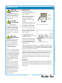
CAUTION:
EQUIPMENT DAMAGE
DO NOT plug in or energize this
appliance until all Installation
Instructions are read and followed.
Damage to the Brewer will occur if
these instructions are not followed.
CAUTION:
BURN HAZARD
Exposed surfaces of the
appliance, brew chamber and
decanter may be HOT to the
touch, and can cause serious
burns.
AGENCY APPROVAL INFORMATION
C
B
C
B
E d
C
E
p
C
E
DO NO
T
p
W
s
t
WARNING
W
a
p
WARNING
W
B
p
W
WARNING
W
T
c
W
W
WARNING
641 p/n 2M-75844 1012 1040 1072 Owners Manual
3
These brewers are listed under ETL 3016449.
This brewer meets
Standard 4 only when installed,
operated and maintained in accordance with the enclosed
instructions.
STD 4
STD 4

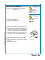
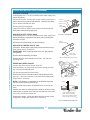
INSTALLATION INSTRUCTIONS
READ THIS CAREFULLY BEFORE STARTING THE INSTALLATION
Unpack the unit. Inspect all components for completeness and
condition. Ensure that all packing materials have been removed
from the unit.
Verify that the Spray Head Gasket (#33) and Spray Disk (#34)
are properly installed.
LEVELING THE UNIT
Verify that an adjustable leg is installed at each corner of the
brewer.
Set Brewer in its operating location. Level the Brewer. A spirit
level should be placed on the top of the unit, at the edge, as a
guide when making level adjustments.
Level the unit from left to right and front to back by turning the
adjustable feet. Be sure all four feet touch the counter to prevent
tipping.
PLUMBER’S INSTALLATION INSTRUCTIONS
Brewer should be connected to a POTABLE WATER, COLD
WATER line. Flush water line before connecting to Brewer.
DO NOT use a saddle valve with a self-piercing tap for the water
line connection. Such a tap can become restricted by waterline
debris. For systems that must use a saddle tap, shut off the
main water supply and drill a 3/16” (minimum) tap for the saddle
connection, in order to insure an ample water supply. Remember
WRÀXVKWKHOLQHSULRUWRLQVWDOOLQJWKHVDGGOH
The brewer must be installed on a water line with average
pressure between 20 PSI and 90 PSI. If your water pressure
exceeds 90 PSI at anytime, a pressure regulator must be
installed in the water supply line to limit the pressure to not more
than 90 PSI in order to avoid damage to lines and solenoid.
A water shut-off valve should be installed on the incoming water
line in a convenient location (Use a low restriction type valve,
VXFKDVDWXUQEDOOYDOYHWRDYRLGORVVRIZDWHUÀRZWKUXWKH
valve.
The provided water line strainer must be installed in the supply
line, between the shutofIYDOYHDQGLQOHW¿WWLQJ1RWH)/2:
arrow marking on strainer body.
IMPORTANT:
To enable the installer to make
a quality installation and to
minimize installation time, the
following suggestions and tests
should be done before the
actual unit installation is started:
CAUTION:
EQUIPMENT
DAMAGE
DO NOT plug in or energize this
appliance until all Installation
Instructions are read and
followed. Damage to the
Brewer will occur if these
instructions are not followed.
CAUTION:
UNSTABLE
EQUIPMENT
HAZARD
It is very important for safety
and for proper operation that the
brewer is level and stable when
VWDQGLQJLQLWV¿QDORSHUDWLQJ
position. Provided adjustable,
non-skid legs must be installed
at each corner of the unit.
Failure to do so will result in
movement of the brewer which
can cause personal Injury and/
or damage to brewer.
NOTE: :ater supply inlet line
must meet certain minimum
criteria to insure successful
operation of the brewer.
%ORRP¿HOGUHFRPPHQGV´
copper tubing for installation of
less than 12 feet and 3/8” for
more than 12 feet from a 1/2”
water supply line.
4
641 p/n 2M-75844 1012 1040 1072 Owmers Manual
C
U
E
H
C
C
Q
C
EQ
D

INSTALLATION INSTRUCTIONS (continued)
NOTE: This equipment must
be installed to comply with
all applicable federal, state
and local plumbing codes and
ordinances.
WARNING:
SHOCK HAZARD
Brewer must be properly
grounded to prevent possible
shock hazard. DO NOT
assume a plumbing line
will provide such a ground.
Electrical shock will cause death
or serious injury.
IMPORTANT: Do not connect
brewer to electrical power until
WKHWDQNLV¿OOHGZLWKZDWHr.
Pour water into the pour-over
RSHQLQJXQWLOZDWHUÀRZVIURP
the brew head.
IMPORTANT:
Supply power must match
nameplate for voltage and
phase. Connecting to the
wrong voltage will damage the
brewer or result in decreased
performance. Such damage is
not covered by warranty.
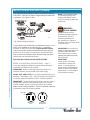
NSF requires that the brewer be able to be moved for cleaning
underneath. AÀH[OLQHRUORRSVRIFRSSHUWXELQJZLOOVDWLVI\WKLV
requirement. See Figure 2 below.
,QVRPHDUHDVORFDOFRGHVUHTXLUHDEDFNÀRZSUHYHQWHU (check
YDOYHWREHLQVWDOOHGRQWKHLQOHWZDWHUOLQH,IDEDFNÀRZ
preventer is used, you must install a water hammer arrester
LQWKHLQFRPLQJOLQHEHWZHHQWKHEDFNÀRZSUHYHQWHUDQGWKH
brewer inlet, as far away from the brewer as space will allow.
7KLVZLOOUHOLHYHWKHH[FHVVLYHEDFNSUHVVXUHVWKDWFDQFDXVH
faucet leaks and solenoid malfunctions.
ELECTRICIAN’S INSTALLATION INSTRUCTIONS
REFER TO ELECTRICAL SPECIFICATIONS - Page 1
Check the nameplate to determine correct electrical service
required for the Brewer to be installed.
IMPORTANT: Before connecting to electricity, make sure
automatic brewers are connected to the water supply.
Models 1012, 1040 & 1072 (US only) are equipped with a cord
and plug. They require a 115 - 125 volt 15 amp circuit (50/60 Hz,
2 wire plus ground, with NEMA 5-15R or 5-20R Receptacle).
IMPORTANT: The ground prong of the plug is part of a system
designed to protect you from electrical shock in the event of
internal damage. Never cut off the ground prong nor twist a
EODGHWR¿WDQH[LVWLQJUHFHSWDFOH&RQWDFWDOLFHQVHGHOHFWULFLDQ
to install the proper circuit and receptacle.
5
IL1615
Fig. 2 Water Supply Installation
641 p/n 2M-75844 1012 1040 1072 Owmers Manual
W
S
H
Brewer mu
NEMA 5-15P
PLUG
GROUND
PIN
NEMA 5-15R
RECEPTACLE
IL1686

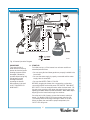
OPERATION
Fig. 4 Brewer Operation Diagram
START-UP
For initial start-up, or if the brewer has not been used for an
extended period of time:
• Be sure spray disk and brew gasket are properly installed in the
brew head.
• Be sure the water supply is properly connected and the water
supply valve is turned ON.
• Be sure the WATER TANK IS FILLED
BEFORE plugging the brewer into a receptacle, or otherwise
connecting brewer to electrical power THE WATER TANK MUST
BE FILLED. Place an empty decanter under the brew head. Lift
the pour-over cover then pour warm tap water into the pour-over
RSHQLQJXQWLOZDWHUÀRZVIURPWKHEUHZKHDG:KHQZDWHUVWRSV
dripping from the brew head, empty the container.
Once the tank is full of water, connect the brewer to electrical
power. For Models 1016 & 1074, press power switch to ON.
The heating elements will begin heating the water in the tank.
When the water has reached the proper temperature, the
“HEAT” LED will go out.
A.IMPORTANT:
Tank must be full of
water before connecting
brewer to electrical power.
Heating elements will be
damaged if allowed to
operate without being fully
submerged in water.
Damage caused by
operating the brewer
without water in the tank
is NOT COVERED BY
WARRANTY.
6
IL2203
641 p/n 2M-75844 1012 1040 1072 Owmers Manual

OPERATION (continued)
7
WATER HEATER
Water temperature is sensed by an electronic water
temperature probe inserted into the water tank.
This temperature signal is fed to the controller.
The setpoint temperature is adjustable. The
controller sends a command signal to the power
board based upon a comparison between the
setpoint temperature and actual temperature.
See page 17.
The power board energizes the heating elements
based on the command signal from the controller.
Excessive temperature will trip the hi-limit safety
switch. The hi-limit will automatically reset when
the brewer cools.
WATER FLOW
POUR-OVER FEATURE
Pouring any amount of water into the pour-over
opening and into the basin pan forces an identical
amount of heated water out of the tank and through
the spray head.
AUTOMATIC OPERATION
Pressing the BREW key energizes the solenoid
valve, allowing water from an external water supply
WRÀRZLQWRWKHZDWHUWDQN The incoming water
forces heated water out of the tank to perform the
brew.
7KHVROHQRLGXVHVDÀRZFRQWUROGHYLFHVRWKDW
ÀRZLVFRQVLVWHQWEHWZHHQSVLDQGSVL
The length of time the solenoid is open is controlled
by the time setting of the controller. See page 18.
$IWHUWKHVROHQRLGFORVHVZDWHUZLOOFRQWLQXHWRÀRZ
to the brew chamber until the water level in the tank
falls below the brew pickup, breaking the siphon.
HOT WATER FAUCET
The faucet water coil is submerged in the hot water
tank and draws heat from the brew water. Wa-
ter going to the water coil is not controlled by the
solenoid valve.
Hot water is provided at the faucet, at supply water
pressure, any time the faucet shut-off valve is
OPEN
.
Fig. 6 Water Flow Diagram
Fig. 5 Heat Control Diagram
,/
,/
641 p/n 2M-75844 1012 1040 1072 Owmers Manual

8
OPERATION (continued)
ELECTRONIC FEATURES
Energizing the Brewer
:KHQHOHFWULFSRZHULVDSSOLHGWRWKHXQLWDOOWKHOLJKWVZLOOÀDVKIRXU
WLPHVDQGIRXUEHHSVZLOOVRXQG 7KHXQLWZLOOEHOFF
Press the ON/OFF key)RXUEHHSVZLOOVRXQGDQGDOOOLJKWVZLOOÀDVK
RQFH The POWER indicator will remain
ON,IWKHZDWHUWHPSHUDWXUH
LVPRUHWKDQ)EHORZWKHVHWSRLQWWKH+(AT indicator will glow until
ZDWHUWHPSHUDWXUHUHDFKHVVHWSRLQW
3UHVVWKH212))NH\DJDLQWRWXUQWKHEUHZHUOFF 7KUHHEHHSVZLOO
VRXQGWKHWDQNKHDWHUDQGDOOZDUPHUVZLOOEHVZLWFKHGRIIDQGDOO
LQGLFDWRUOLJKWVZLOOJRRXW
Brew Settings
6HHSDJHVIRUVHWWLQJ%UHZ Time and THPSHUDWXUH
ABS™ (Automatic Brew Start)
6WDUWDEUHZE\SUHVVLQJ%5(W AVLQJOHEHHSZLOOVRXQG The system
ZLOOYHULI\WKDWWKHZDWHULQWKHWDQNLVDWWKHSURSHUWHPSHUDWXUH,ILWLV
EUHZZLOOVWDUWLPPHGLDWHOy2WKHUZLVHWKH%5(:LQGLFDWRUZLOOÀDVK
%UHZWaiting Mode) until the water reaches setpoint temperature,
WKHQWKHLQGLFDWRUZLOOJORZDQGEUHZZLOOFRPPHQFH,IWKHPDLQ
warmer is oIILWZLOOEHHQHUJL]HGDXWRPDWLFDOOy
$WWKHFRQFOXVLRQRIWKHEUHZF\FOHWKUHHEHHSVZLOOVRXQG
NOTE: TRRYHUULGH%UHZWDLWLQJ0RGHSUHVVDQGKROGWKH%5(:NH\
IRUVHFRQGVZKLOHWKH%5(:LQGLFDWRULVÀDVKLQJ%UHZZLOOEHJLQ
UHJDUGOHVVRIZDWHUWHPSHUDWXUH TRDYRLGXQGHUWHPSHUDWXUHEUHZV
WKLVIHDWXUHVKRXOGRQO\EHXVHGZKHQVHWWLQJEUHZYROXPHV
NOTE: %UHZWDLWLQJ0RGH%5(:LQGLFDWRUÀDVKLQJSUHYHQWV
PXOWLSOHXQDWWHQGHGEUHZV:KLOHWKH%5(:LQGLFDWRULVRQRU
ÀDVKLQJDQ\DGGLWLRQDOVWURNHVRIWKH%5(:NH\ZLOOEHLJQRUHGWKHUH
ZLOOEHDEHHSHDFKWLPHWKHNH\LVSUHVVHGKRZHYHU $QRWKHUEUHZ
FDQQRWEHLQLWLDWHGXQWLOWKHSUHYLRXVEUHZLVFRPSOHWH
7KH%UHZWaiting Time, also called Dripout TLPHLQWHUYDOEHWZHHQ
ZKHQWKHEUHZLVLQLWLDWHGDQGWKHDXGLEOHVLJQDOVRXQGVDWWKHHQG
RIWKHEUHZPD\EHDGMXVWHGEHWZHHQDQGPLQXWHVDWWKH%UHZ
Signal Timer dial on the controller6HHSDJH
Brew Cancel
TRFDQFHODEUHZLQSURJUHVVRUDEUHZLQZDLWLQJSUHVVWKH&$1&(L
key TZREHHSVZLOOVRXQGDQGWKH%5(:LQGLFDWRUZLOOJRRXW
NOTE: ,IDEUHZLQSURJUHVVLVFDQFHOOHGFRIIHHZLOOFRQWLQXHWRÀRZ
XQWLODOOZDWHUGHOLYHUHGKDVGULSSHGWKURXJKWKHEUHZFKDPEHr
IMPORTANT:
DO NOTHQHUJL]HWKLV
EUHZHUXQWLOWKHZDWHU
WDQNKDVEHHQ¿OOHG'U\
¿ULQJZLOOGDPDJHKHDWLQJ
HOHPHQWV6HHSDJH
641 p/n 2M-75844 1012 1040 1072 Owmers Manual
Fig. 7 Turning Brewer
ON or OFF
Fig. 8 Initiate a Brew
Fig 9 Brew Cancel
,/

OPERATION (continued)
Quality Timer is normally
set for 30 minutes. It can
be set for 20 minutes by
moving a jumper on the
controller. See page 17.
After Hours™ is an energy
saving feature. The brew-
er will enter After Hours™
mode if it is not used for
three hours.
Press the BREW key
to immediately return
the brewer to normal
operation.
IMPORTANT:
If the original cause of
the problem has not been
addressed, the brewer will
once again go into Over
Temperature mode four
minutes after being reset.
Quality Timer
Coffee looses its freshness as it sits on a warmer. The Quality Timer
ÀDVKHVWKHZDUPHUOLJKWVPLQXWHVDIWHUWKHODVWEUHZWRUHPLQG\RX
that the coffee is nearing the end of its useful life.
After Hours™ Operation
During normal operation, the controller will maintain the precise
brewing temperature. If, however, if the BREW key in not pressed for
3 hours, the brewer goes into After Hours™ mode; any warmer left on
will be turned off; and, the temperature will only be maintained to within
20ºF. This feature prolongs component life and saves energy.
As soon as the BREW key is pressed, the brewer returns to normal
operation, heating the water to the precise temperature before
beginning the brew. The brewer will return to After Hours™ mode only
if three hours pass without a brew being initiated.
Disable/Enable After Hours™ Feature
To disable After Hours™, press the ON/OFF key to turn the brewer
OFF.
Press and hold the CANCEL key until two beeps sound, and the HEAT
LQGLFDWRUÀDVKHVWZLFH This feature is now disabled.
To re-enable After Hours™, press the ON/OFF key to turn the brewer
OFF. Press and hold the CANCEL key until three beeps sound, and the
32:(5LQGLFDWRUÀDVKHVWZLFH This feature is now enabled, however,
it will not be activated unless no brew is initiated for three hours.
Over-Temperature and Temperature Fault Protection
Should the water temperature exceed 214ºF (101ºC), or if the control-
ler does not detect a 2ºF (1ºC) rise in temperature within four minutes
of calling for heat, the brewer will go into Over Temperature Mode; the
heating element is turned off, all warmers are disabled and all lights will
ÀDVK
Possible causes of Over Temperature condition:
Setpoint is in the boiling range.
Heating element or temperature probe has malfunctioned.
Excessive scale buildup is preventing the element from heating the
water.
Heating element relay fails in the “on” state.
No water in the tank.
Hi-limit safety tripped (must be manually reset)
To reset the brewer:
Determine the cause of the failure and take appropriate remedial
action to rectify the problem.
Press and hold the CANCEL key for three seconds. Four beeps will
sound and the brewer will resume normal operation.
9
641 p/n 2M-75844 1012 1040 1072 Owmers Manual

10
BREWING COFFEE
CAUTION:
BURN HAZARD
Exposed surfaces of the
brewer, brew chamber and
decanter may be HOT to
the touch, and can cause
serious burns.
CAUTION:
BURN HAZARD
To avoid splashing or
RYHUÀRZLQJKRWOLTXLGV
ALWAYS place an empty
decanter under the brew
chamber before starting
the brew cycle. Failure to
comply can cause serious
burns.
CAUTION:
BURN HAZARD
After a brew cycle, brew
chamber contents are
HOT. Remove the brew
chamber and dispose of
used grounds with care.
Failure to comply can
cause serious burns.
NOTE: The brewer will not
initiate a second automatic
brew cycle until the current
cycle plus the drip-out time
is completed. If the BREW
key is pressed during this
time, the BREW light will
ÀDVKLQGLFDWLQJDEUHZLQ
progress.
NOTE: Water for the hot
water faucet is heated in
a coil inside of the water
tank. Use of the faucet will
not affect the volume of
water delivered for a brew.
However, overuse of the
faucet during a brew may
lower the temperature of
the brew water.
A
A
U
s
CA
CA
BU
Exposed
s
C
B
T
id
T
A
U
r
CA
BU
Af
te
r
a
br
PREPARATION
Place one (1) genuine
%ORRP¿HOGSDSHU¿OWHULQWKH
brew chamber.
Add a pre-measured amount
of fresh coffee grounds.
Gently shake the brew
chamber to level the bed of
grounds.
Slide the brew chamber into
place under the brew head.
B. AUTOMATIC OPERATION
BE sure HEAT light is not lit.
Place the appropriate EMPTY
decanter in place under the
brew chamber.
Press the BREW switch.
The BREW light will glow and
a beep will sound.
The solenoid will open for an
amount of time determined by
the timer setting, admitting a
PHDVXUHGTXDQWLW\RIZDWHU
into the tank.
Inlet water will displace a like amount of heated water from the tank.
The hot water will be forced into the brew head where it will spray
over the bed of grounds. Freshly brewed cofIHHZLOOEHJLQWR¿OOWKH
container under the brew chamber.
At the end of the brew cycle, plus an amount of time set to allow all
water to drip out of the brew chamber, three beeps will sound.
:KHQWKHÀRZDQGDOOGULSSLQJVWRSVWKHFRIfee is ready to serve.
Discard the contents of the brew chamber and rinse it in a sink.
When the HEAT light goes out, the brewer is ready for another
brew cycle.
C. WARMERS
At the start of a brew, the MAIN warmer is energized automatically.
Press either the FRONT or REAR warmer switch to energize an
auxiliary warmer6HWWKH¿OOHGGHFDQWHURQWKHVHOHFWHGZDUPHUWR
keep it warm.
A.
IL1605
PAPER
FILTER
BREW
CHAMBE
R
Fig. 10 Prepare Brew Chamber
Fig. 11 Press BREW to Start
641 p/n 2M-75844 1012 1040 1072 Owmers Manual

CLEANING INSTRUCTIONS
PROCEDURE: Clean Coffee Brewer
PRECAUTIONS: Disconnect brewer from electric power.
Allow brewer to cool.
FREQUENCY: Daily
TOOLS: Mild Detergent, Clean Soft Cloth or Sponge
Bristle Brush.
1. Disconnect brewer from electric power.
Allow brewer to cool before cleaning.
2. Remove and empty decanters.
3. Remove and empty brew chamber.
4. 5HPRYHWKHVSUD\GLVNIURPWKHEUHZKHDG6HH¿JXUH
Press up on the spray disk ears, and then turn the disk to
the left to unlatch. Remove the gasket from inside the brew
head.
5. Wipe inside of brew head and area around the brew head
with a soft clean cloth or sponge moistened with clean water.
6. Wash the spray disk in a sink using warm water and a mild
detergent. A bristle brush may be used to clear clogged
spray holes. Rinse the spray disk with clean water and allow
to air dry.
7. Wash the brew chamber in a sink using warm water and a
mild detergent. A bristle brush may be used to clean the
inside. Rinse with clean water and allow to air dry. For
stainless steel brew chambers, be sure the wire rack is prop-
erly reinstalled.
Wipe the exterior of the brewer with a soft clean cloth or
sponge moistened with clean water.
9. Reinstall the gasket INSIDE the brew head, then reinstall the
spray disk.
10. Reinstall the brew chamber.
11. Decanters may be washed in a dishwasher or sink.
Procedure is complete
CAUTION:
BURN HAZARD
Brewing and serving
temperatures of coffee are
extremely hot.
Hot coffee will cause
serious skin burns.
CAUTION:
SHOCK HAZARD
Do not submerge or immerse
brewer in water.
IMPORTANT:
DO NOT use steel wool, sharp
objects, or caustic, abrasive or
chlorinated cleansers to clean
the brewer.
A
A
U
Brewing an
CA
CA
B
U
Brewing an
C
A
S
H
Do
n
ot
s
ub
m
Fig. 12 Cleaning
IL1677
11
641 p/n 2M-75844 1012 1040 1072 Owmers Manual

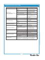
TROUBLESHOOTING SUGGESTIONS
12
SYMPTOM POSSIBLE CAUSE SUGGESTED REMEDY
Water won’t heat
(NOTE: Models 1016 & 1074 must
have power switch ON)
Brewer unplugged or circuit breaker
tripped
Check power supply cord,
Check / reset circuit breaker
Temperature adjusted too low or set
to off
Turn on and set for desired
temperature. See page 15
Hi-Limit thermostat tripped Allow to cool
Damaged internal component or
wiring
Examine wiring & connectors,
controller, power board and
heating element, Repair/replace
as needed
Coffee level too high or low Timer out of adjustment Adjust controller. See page 17
%UHZFKDPEHURYHUÀRZV
TRRPDQ\¿OWHUSDSHUVRUZURQJ¿OWHU
paper
8VHRQHJHQXLQH%ORRP¿HOG
¿OWHUSHUEUHZ
Brew chamber dispense hole
plugged
Thoroughly clean brew chamber
Sprays water from brew head Spray gasket improperly installed
Check/reinstall gasket on INSIDE
of brew head
1REUHZZKLOHIDXFHWÀRZV2.
Spray disk plugged Clean spray disk
Damaged internal component or
wiring
Check keypad, controller,
power board & solenoid,
Repair, replace as needed
1REUHZSOXVQRÀRZIURPKRWZDWHU
faucet
Water supply OFF Turn water supply ON
Solenoid screen plugged Clean solenoid screen
Water line strainer (if used) plugged Clean strainer
1RÀRZIURPKRWZDWHUIDXFHW
WDWHU¿OWHULIXVHGSOXJJHd 5HSODFH¿OWHUHOHPHQW
Faucet valve turned OFF Turn faucet valve ON
Faucet plugged Disassemble faucet, clean
Poor coffee quality
.HHSEUHZHUDQGGHFDQWHUVFOHDQ,QVWDOODWDVWHDQGRGRU¿OWHULQZDWHU
supply, and replace cartridges regularly. Use a quality coffee with a
consistent roast. Use proper grind and amount of coffee per brew.
641 p/n 2M-75844 1012 1040 1072 Owmers Manual

CAUTION:
SHOCK HAZARD
Live electrical circuits may
be exposed while performing
these procedures.
These procedures are to
EHSHUIRUPHGE\TXDOL¿HG
technical personnel only.
O
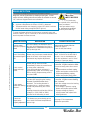
ERROR DETECTION
13
WHAT TO CHECK DESCRIPTION CORRECTIVE ACTION
Has the water
tank been properly
¿OOHG"
On initial startup, an attempt to heat a
dry tank will be detected as too high a
WHPSHUDWXUHRULQVXI¿FLHQWWHPSULVHRU
will trip the high limit.
TDQNPXVWEHSURSHUO\¿OOHGDV
detailed on page 6.
Check hi-limit (see below)
Has hi-limit safety
thermostat tripped
ofI"
Brewer may have been started without
water in the tank, or the temp control
thermostat may require adjustment.
Access hi-limit by removing front
panel. Hi-limit is on the left side of
the tank. Use an insulated tool to
push the red button in until it “clicks”
and stays. Reset per above.
Check control
board and temp
probe.
Brewer will go into error mode
immediately if either the control board
or temp probe is defective.
Temp probe electrical resistance is
approximately 30K at room temp, and
2K at boiling. Replace temp probe if
less than 1K
Reset by holding the CANCEL key for
VHFRQGV,IOLJKWVFRQWLQXHWRÀDVK
Disconnect temp probe from control
board.
D,IOLJKWVFRQWLQXHWRÀDVKXQSOXJ
brewer and replace control board.
E,IOLJKWVVWRSÀDVKLQJXQSOXJ
brewer and replace temp probe.
Check power
board and heating
element..
Brewer will go into error mode 4
minutes after energizing the heating
HOHPHQWLILQVXI¿FLHQWKHDWULVHLV
detected. The heating element is
energized by an electronic power
board, and protected by the hi-limit
safety.
Heating element should receive full line
voltage (i.e. 120V, 208V or 240V).
Be sure the hi-limit safety is reset.
Reset by holding the CANCEL key for
VHFRQGV,IOLJKWVUHVXPHÀDVKLQJ
DIWHUPLQXWHV
Check the voltage across the heating
HOHPHQWWHUPLQDOV
a. If no voltage is present, unplug
brewer and replace power board.
b. If proper voltage is present,
unplug brewer and replace tank
heating element.
Is the brew
temperature
SURSHUO\DGMXVWHG"
The brewer may occasionally go into
error mode if the brew temperature is
set too high.
See page 17 for temperature
adjustment procedure.
This brewer is designed to perform a continuous internal
GLDJQRVLVDQGWRVLJQDOIDXOWVE\ÀDVKLQJDOOWKHOLJKWV,QIDXOW
PRGHZDUPHUVKHDWLQJHOHPHQWDQGZDWHU¿OOVROHQRLGDUHWXUQHG
“off”, and most keypad functions are disabled.
(UURUGHWHFWLRQDOOOLJKWVÀDVKLQJZLOORFFXUXQGHUWZRFRQGLWLRQV
Anytime a temperature in excess of 214ºF is detected.
Temperature does not change by at least 2ºF within 4 minutes
of tank heater being energized (HEAT light on).
To reset the brewer after the fault has been corrected, press and
hold the CANCEL key for 3 seconds, or disconnect the brewer from
electrical power for three seconds.
Li l t i
CA
S
H
Li l t i
C
641 p/n 2M-75844 1012 1040 1072 Owmers Manual

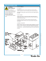
SERVICING INSTRUCTIONS
CAUTION:
SHOCK HAZARD
Opening access panels or
removing warmer plates on this
brew may expose uninsulated
electrical components.
Disconnect brewer from
electrical power before
removing any panel or warmer
plate.
ACCESS PANELS
TOP PANEL:
Remove top panel to access hot water tank, thermo probe,
heating elements, brew circuit tubing, faucet valve and piping.
Top panel is held by two screws at the rear and a retaining lip at
the front.
FRONT PANEL:
Upper front panel is held by two screws at the bottom and a
retaining lip at the top. Lower panels are held by retaining clips
under the warmer plates.
Remove front panel to access controller and power board.
Solenoid on Models 1040 & 1072 are accessible through the
front panel.
WARMER ELEMENTS:
Warmer plates screw to the bracket, and are locked by a nut from
below. For lower warmers, remove the appropriate hole plug to
access the nut. For top panel warmers, remove the top panel to
access the nut. Remove the warmer plate to access the warmer
element.
Fig. 13 Access Panels
14
641 p/n 2M-75844 1012 1040 1072 Owmers Manual
IL2207
A
H
c
CA
S
H
Op
enin
g
ac

SERVICING INSTRUCTIONS (continued)
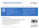
TEMPERATURE ADJUSTMENT
Unplug power cord or turn circuit breaker OFF. Remove top
panel. Remove button plug from front panel.
Pull vent tube out of tank lid and insert a thermometer of known
accuracy in vent hole. Reconnect brewer to electrical power.
Place empty container under brew chamber. Energize brewer
and pour one decanter (64 oz.) of cold water into pour-over
opening. When HEAT light goes out, read the temperature
displayed on thermometer.
Adjust WATER TEMP dial on controller; clockwise increases
temperature. Refer to Table 1 below for proper brewing
temperature based on altitude.
Upon completion, remove thermometer and reinstall vent tube.
Fig. 14 Checking and Adjusting Brew Temperature
CAUTION:
SHOCK HAZARD
These procedures involve
exposed electrical circuits.
These procedures are to
EHSHUIRUPHGE\TXDOL¿HG
technical personnel only.
NOTE: Optimum brewing
temperature is 195ºF to 205ºF
(90ºC to 96ºC).
Maximum temperature setting
should be no more than 205ºF
(96ºC).
IMPORTANT:
An electronic temperature con-
troller will maintain temperature
within ±2ºF.
To prevent boiling water in
the brewer, controller should
be adjusted to a maximum
temperature equal to the local
boiling temperature minus 2ºF,
or 205ºF, whichever is less.
15
641 p/n 2M-75844 1012 1040 1072 Owmers Manual
CA
CA
S
H
Th
es
e
pr
oc
e
Table 1 Boiling Temperature by Altitude
ELEVATION (feet above seal level)
0
5
0
0
1
,
0
0
0
1
,
5
0
0
2
,
0
0
0
2
,
5
0
0
3
,
0
0
0
3
,
5
0
0
4
,0
0
0
4
,5
0
0
5
,
0
0
0
5
,5
0
0
6
,0
0
0
6
,
5
0
0
T
E
M
P
.
(
º
F
)
195
200
205
210
190
IDEAL
BREWING
TEMPERATURE
RANGE
MAXIMUM
TEMPERATURE
SETTING
BOILING
POINT OF
WATER
IL2208
IL2209

SERVICING INSTRUCTIONS (continued)
IMPORTANT: Water pressure
must be between 20 p.s.i and
SVLÀRZLQJSUHVVXUH,I
water pressure exceeds this
YDOXHRULIZDWHUSUHVVXUH
YDULHVJUHDWOy, a pressure
UHJXODWRUPXVWEHLQVWDOOHGLQ
the water supply line.
IMPORTANT: %HIRUHVHWWLQJ
DVVHPEO\LQWRWDQNPDNHVXUH
WDQNOLGJDVNHWLVSURSHUO\
VHDWHGRQÀDQJHRIOLG
DO NOT OVER-TIGHTEN.
IMPORTANT: :KHQUHSODFLQJ
WHPSHUDWXUHSUREHEHVXUHD
new seal washer is in place
DURXQGWKHSUREH TLJKWHQMDPE
ORFNQXWRQO\HQRXJKWRHQVXUH
QRZDWHUOHDNDJH([FHVVLYH
WLJKWHQLQJLVQRWQHFHVVDUy.
IMPORTANT: :KHQUHSODFLQJ
KHDWLQJHOHPHQWDOVRUHSODFH
VHDOJDVNHWV
BREW TIME ADJUSTMENT
7KHDPRXQWRIZDWHUGLVSHQVHGDXWRPDWLFDOO\GXULQJDEUHZF\FOH
LVFRQWUROOHGE\WKH62/(12,' 7,0(GLDORIWKHFRQWUROOHr.
Place empty decanter under brew chamber3UHVV%5(:
EXWWRQ%UHZHUVKRXOGGLVSHQVHRQHIXOOGHFDQWHURIZDWHr.
TRDGMXVWDPRXQW
5HPRYHEUHZFKDPEHUDQGEXWWRQSOXJ2QWKHFRQWUROOHrDGMXVW
62/(12,' 7,0(GLDO%5(: 7,0(FORFNZLVHLQFUHDVHVWLPH
5XQVHYHUDOF\FOHVWRFKHFNDPRXQWRIZDWHUGHOLYHUHG
DRIPOUT TIME ADJUSTMENT
WDWHUGHOLYHUHGWRWKHEUHZFKDPEHUZLOOWDNHDZKLOHWRGULS
WKURXJKDVFRIIHH 7KHWLPHEHWZHHQWKHHQGRIDEUHZDQG
ZKHQDQHZEUHZFDQEHLQLWLDWHGLVFRQWUROOHGE\WKH%5(:
6,*1$/ 7,0(5 $GMXVWWKH%5(:6,*1$/ 7,0(5GLDORQWKH
FRQWUROOHUWRDFFRXQWIRUWKHGULSRXWWLPH5HSODFHEXWWRQSOXJ
REMOVE TANK LID ASSEMBLY
8QSOXJEUHZHURUWXUQFLUFXLWEUHDNHUOFF. Turn OFF water
supply5HPRYHWRSSDQHO3XOOYHQWWXEHDQGLQOHWHOERZRXWRI
basin pan.
2QDXWRPDWLFPRGHOVSXOOZDWHULQOHWWXEHRXWRIEDVLQSDQ
5HPRYHEDVLQSDQ
2QPRGHOVZLWKIDXFHWGLVFRQQHFWLQOHWSLSHDWIDXFHWVKXWRII
YDOYHDQGRXWOHWSLSHDWIDXFHW
'LVFRQQHFWDOOZLULQJIURPKLOLPLWDQGKHDWLQJHOHPHQW
'LVFRQQHFWWHPSHUDWXUHSUREHIURPFRQWUROOHr.
/RRVHQFHQWHUVFUHZRQWDQNKROGGRZQEUDFNHW5HPRYH
KROGGRZQEUDFNHWE\VOLGLQJVKRUWVORWWHGHQGRIIRIORFNLQJVWXG
DQGOLIWLQJLWRII 5HPRYHFRYHUDVVHPEO\E\OLIWLQJLWVWUDLJKWXS
5HDVVHPEOHLQUHYHUVHRUGHr.
REPLACE TEMPERATURE PROBE
8QSOXJEUHZHURUWXUQFLUFXLWEUHDNHUOFF5HPRYHWRSSDQHO
/RRVHQDQGIUHHMDPQXWIURPSDVVWKUX¿WWLQJVHFXULQJ
WHPSHUDWXUHSUREH'LVFRQQHFWWHPSHUDWXUHSUREHZLULQJ
FRQQHFWRUIURPFRQWUROOHr.
/LIWRXWSUREHMDPEQXWDQGJDVNHW
5HDVVHPEOHLQUHYHUVHRUGHr.
REPLACE HEATING ELEMENT
5HPRYHWDQNOLGDVVHPEO\SHUDERYH
5HPRYHWZRKH[QXWVKROGLQJHOHPHQWWRFRYHr. Pull element
IURPPRXQWLQJKROHV
5HDVVHPEOHLQUHYHUVHRUGHr.
Fig. 15 Adjust BrewTime
and Dripout Time
16
,/
BREW TIME
DRIPOUT TIME
W
A
W
W
TER
A
A
T
EM
P
(°
F
)
SOLENOID TIMER
(WATER VOLUME)
(SECONDS)
BREW SIGNAL TIMER
- BREW LIGHT
END OF BREW BEEPER
(MINUTES)
10
20
2
3
4
5
6
7
8
30
40
50
60
70
80
O
FF
185
190
195
200
205
641 p/n 2M-75844 1012 1040 1072 Owmers Manual

SERVICING INSTRUCTIONS (continued)
17
REPLACE SOLENOID
Unplug power cord. Turn OFF and disconnect water supply from
EUHZHULQOHW¿WWLQJ
Remove front panel. Remove two screws holding access door in
SODFH5HPRYHDFFHVVGRRUDQGVROHQRLG8QVFUHZLQOHW¿WWLQJ
cap to release solenoid from door.
Remove wiring from solenoid.
Large end of wrench 86660 can be used to hold solenoid inlet
¿WWLQJZKLOHGLVFRQQHFWLQJVXSSO\OLQH
REPLACE FAUCET SUPPLY HOSE
Unplug power cord. Turn OFF and disconnect water supply from
EUHZHULQOHW¿WWLQJ'LVFRQQHFWKRVH¿WWLQJIURPVROHQRLG6HH
illustration at right).
'LVFRQQHFWKRVHÀDUH¿WWLQJIURPWDQNFRLO¿WWLQJ
REPLACE HOT WATER FAUCET COIL
6\PSWRP%UHZHUGULSVFRQWLQXRXVO\IURPEUHZKHDGH[FHSW
when faucet valve is turned OFF.)
IMPORTANT: :KHQUHSODFLQJZDWHUIDXFHWFRLODOVRUHSODFH
VHDOJDVNHWV
5HPRYHWDQNOLGDVVHPEO\SHUDERYH
5HPRYHWZRKH[QXWVKRWZDWHUFRLOWRFRYHr. Pull coil from
mounting holes.
REPAIR HOT WATER FAUCET
Remove top panel and turn faucet valve OFF.
Unscrew aerator cap from faucet and remove handle retaining
FOLS'RQRWOHWIDXFHWERG\WXUQ
Pull bonnet assembly from faucet body.
([DPLQHWKHLQWHULRURIWKHIDXFHWERG\DQGWKHVXUIDFHRIWKH
seat cup. Clean out any debris in the faucet bodyXVLQJDVWLff
bristle brush if necessary.
NOTE: $Q\DEUDVLRQRUURXJKQHVVRQWKHÀDWHQGRIWKHVHDW
FXSZLOOUHTXLUHUHSODFLQJWKHVHDWFXS
WRUNWKHVHDWFXSRXWRIWKHERQQHWDQGRff of the end of the
stem.
,QVWDOODQHZVHDWFXSPDNLQJVXUHWKHNQRERQWKHVWHPLVIXOO\
LQVHUWHGLQWRWKHSRFNHWRIWKHVHDWFXSDQGWKHVNLUWRIWKHVHDW
cup is fully inserted into the bonnet.
([DPLQHWKHDHUDWRr&OHDQDQ\GHEULVIURPWKHVFUHHQRUÀRZ
straightenerXVLQJDVWLff bristle brush if necessary.
Fig. 16 Fill Solenoid
Fig. 17 86660 Solenoid Wrench
P/N 2C-76660 Braided Hose Wrench
BYPASS
OUTLET
5/8” for VALVE
FLARE FITTING
7/16” for
BRAIDED HOSE
METAL FITTING
2C-76660 WRENCH
WRENCH
METAL FITTING
CLINCH RING
SLIDE WRENCH BETWEEN
VALVE AND HOSE FITTING
PRESS CLINCH RING TOWARD
METAL FITTING TO RELEASE
WHITE
CLINCH
RING
IL2619
641 p/n 2M-75844 1012 1040 1072 Owmers Manual
SCREEN
SOLENOID
WASHER
INLET
FITTING
CAP
IL1693a
Fill
Solenoid

REPLACE HOT WATER FAUCET COIL
(Symptom: Brewer drips continuously from brew head, except
when faucet valve is turned OFF.)
Remove tank lid assembly per above.
Remove two hex nuts hot water coil to cover. Pull coil from
mounting holes.
Reassemble in reverse order.
REPAIR HOT WATER FAUCET
Remove top panel and turn faucet valve OFF.
Unscrew aerator cap from faucet and remove handle retaining
clip. Do not let faucet body turn.
Pull bonnet assembly from faucet body.
Examine the interior of the faucet body and the surface of the
seat cup. Clean out any debris in the faucet body, using a stiff
bristle brush if necessary.
Examine the aerator&OHDQDQ\GHEULVIURPWKHVFUHHQRUÀRZ
straightener, using a stiff bristle brush if necessary.
Reassemble in reverse order.
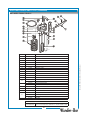
REPLACE CONTROLLER
Unplug power cord or turn circuit breaker OFF.
Remove front panel. Remove timer faceplate. Use needle
QRVHSOLHUVWRGLVHQJDJHWKUHHEDUEHG¿WWLQJVKROGLQJFRQWUROOHU
to bracket. Disconnect keypad ribbon cable (note position “1”),
temperature probe and power board cable.
Set jumpers as described on page 19.
Reassemble in reverse order.
Adjust controller as described on pages 15 & 16.
IMPORTANT: When replacing
water faucet coil, also replace
seal gaskets.
NOTE: Any abrasion or
URXJKQHVVRQWKHÀDWHQGRIWKH
seat cup will require replacing
the seat cup:
Work the seat cup out of the
bonnet and off of the end of the
stem.
Install a new seat cup, making
sure the knob on the stem is
fully inserted into the pocket of
the seat cup, and the skirt of the
seat cup is fully inserted into the
bonnet.
REPLACE
H
OT
W
A
W
TER
A
A
F
AUCET COIL
F
IMPOR
T
AN
T
T
:
When replacing
SERVICING INSTRUCTIONS (continued)
18
Fig. 18 Controller Hook-Up
IL2620
KEYPAD
RIBBON
CABLE
TEMP
PROBE
POWER
BOARD
CONNECTOR
641 p/n 2M-75844 1012 1040 1072 Owmers Manual
La page charge ...
La page charge ...
La page charge ...
La page charge ...
La page charge ...
La page charge ...
La page charge ...
La page charge ...
La page charge ...
La page charge ...
La page charge ...
La page charge ...
La page charge ...
La page charge ...
La page charge ...
La page charge ...
-
 1
1
-
 2
2
-
 3
3
-
 4
4
-
 5
5
-
 6
6
-
 7
7
-
 8
8
-
 9
9
-
 10
10
-
 11
11
-
 12
12
-
 13
13
-
 14
14
-
 15
15
-
 16
16
-
 17
17
-
 18
18
-
 19
19
-
 20
20
-
 21
21
-
 22
22
-
 23
23
-
 24
24
-
 25
25
-
 26
26
-
 27
27
-
 28
28
-
 29
29
-
 30
30
-
 31
31
-
 32
32
-
 33
33
-
 34
34
-
 35
35
-
 36
36


Bloomfield EBC™ 2 Warmer Brewer Le manuel du propriétaire
- Catégorie
- Cafetières
- Taper
- Le manuel du propriétaire
- Ce manuel convient également à
dans d''autres langues
Documents connexes
Autres documents
-
Waring WCM60PT Manuel utilisateur
-
Waring Commercial WCM70PAP Series Manuel utilisateur
-
 Grabber HWES Mode d'emploi
-
Saeco 10001598 Manuel utilisateur
-
 Dyconn Faucet MH2611-C11 Guide d'installation
-
GE G7CDABSSPSS Le manuel du propriétaire
-
-
Saeco RI9829/11 Manuel utilisateur
-
GEAppliances PFE28RSH Technical Service Manual
-

