
Note: Product images shown may be different than actual
product received.
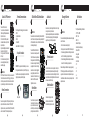
Cable connectors at the other end of the cable provide an interface
to other systems for communications, to allow local downloading
and to provide power. Additionally some cables allow connecting
peripherals such as check readers and printers. All of the cable
connectors are labeled and color-coded, as follows:
• DC Power - Connects AC power adapter to the Q30
• RS232A (Blue, RJ11 6P4C), RS232B (Yellow, RJ11 6P4C), or
RS232 on C302 hub cable (RJ11 6P6C) - Connects an external
POS device or check reader
• RS232 (Black, DB9-F) – Used to connect to POS terminal
• USB-Host (Type A) or Micro USB 2.0 - Used for local terminal
downloads or external peripherals
• LAN (Red, Ethernet, RJ45-F) - Used for bi-directional Ethernet
connections, TMS, and/or payment processing
• Powered USB - to connect to POS/ECR systems
Quick Setup Guide
PAX™ Q30 Payment Terminal
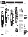
Box Contents
Box Contents
Communication cable
(cable type varies by configuration)
AC power adapter
(included in some configurations)
• 1 - PAX™ Q30 payment terminal
• 1 - Communication cable (varies by configuration)
• 1 - AC power adapter (not included with PUSB configurations)
• 1 - Privacy shield
• 1 - Quick Setup Guide
Product Description
Product Description
Stylus pen
Contactless reader
Camera
Touch screen
Speaker(inside)
Magnetic
stripe reader
Privacy shield
Keypad
Smart card reader
Back cover
MAC label
Regulatory label
Part number/
serial number label
Screw
Screw(under rubber foot)
Reset button Audio jack
Cable Connectors
Cable Connectors
3
2x7P connector
The 2x7P connector end of the
provided communication cable
connects to the underside of the Q30.
A combination of the following ports are available on the
communication cable (depending on the Q30 configuration):
Privacy shield
Note: Stylus pen is an optional configuration for the terminal, it
may be not support on actual product received.
P/N:200312000000402

910
Power down and remove all power from
the Q30. Unscrew and open back cover.
Gently press and slide SIM or Micro SD
door toward outer edge of terminal and
open hinged door. Seat card with gold
connectors down into slot, aligning with
opening. Gently press and slide door
toward center of terminal to lock door
closed. Close Q30 back cover and
tighten back cover screw.
Audio JackAudio Jack
WARNING:
Power down the terminal before installing SIM cards or Micro SD
cards. If the terminal is still powered on during an attempted SIM
or SD card installation or removal, both the terminal and the card
can be damaged irreparably.
Audio Jack is an optional configuration for the terminal, it may be
not support on actual product received.
If required, a visually disabled person can connect a headphone
to the terminal for audio prompting if the terminal application
supports this using the 3.5mm output audio jack.
Terminal Location
11
Terminal Location
Insert metal stand prongs into three
stand slots on underside of terminal.
Slide terminal firmly into place on stand.
Stand Installation
12
Stand Installation
Do not use industrial strength or abrasive cleaner as it may damage
or scratch the screen.
• Do not immerse device in water (or liquid).
• Do not spray water or cleaner into EMV Card Reader or ports.
• To clean screen, apply distilled water or mild glass cleaner onto
a soft, lint-free cloth and gently wipe terminal screen.
• To clean terminal, apply distilled water or plastic-safe cleaner
onto a soft, lint-free cloth and gently wipe terminal.
Attach 2x7P Connector
Attach 2x7P Connector
4
To connect 2x7P end of cable:
1. Loosen the screw on the underside of
the Q30 using a Philips head screwdriver.
2. Open the back cover.
3. Place the 2x7P end of the provided
communication cable over its port, but do
not push into place.
4. Align rubber sliding pull restraint so that
it seats into its notch on the Q30.
5. Firmly press the 2x7P end of the cable
into the port.
6. Close the back cover and tighten the
screw, ensuring the gasket is properly
seated in the opening.
DO NOT connect the other end to the AC power source until all
the other cables are connected first. Plugging in the AC power
cord to the power source before the other cables are installed
may result in damage to the terminal or connected devices.
WARNING:
Power Connections
Power Connections
5
Power can be supplied to the Q30 by connecting the AC power
adapter to the data cable, as in the case of RS232 or USB
configurations, or via a powered USB cable (12V Powered USB)
where the connected POS terminal provides the power.
The Q30 supports the following types of communications:
• RS232
• High Speed Ethernet
• USB 2.0
• Powered USB
• Bluetooth BLE 4.0 + Wi-Fi (optional)
Terminal Communications
Terminal Communications
6
SIM and Micro SD Card Installation
8
SIM and Micro SD Card Installation
To install a SIM and/or Micro SD card:
Reset Button
9
Reset Button
To reset the terminal, press and hold
the reset button for 4-6 seconds. using
a pen or similar item. An example of
when this may be used is when you are
performing a download via USB stick.
Locate the terminal on a counter top, desktop, or table top. It is
recommended to keep the terminal away from direct sunlight,
excessive dust, moisture, and heat. Avoid locating the terminal
near electrical devices that might introduce interference such as
microwave ovens and blow dryers.
Cleaning the Device
13
Cleaning the Device
WARNING:
Caution: Changes or modifications not expressly approved by
PAX Technology could void the user’s authority to operate the
equipment. In a domestic environment, this product may cause
radio interference in which case the user may be required to take
adequate measures.
Certifications
14
Certifications
The Q30 passed the following certifications:
• PCI PTS 5.x, SRED
• EMV L1 & L2
• EMV CL L1
• Mastercard PayPass
• American Express Expresspay
• Discover D-PAS
• Visa payWave
• JCB J/Speedy
• Interac Flash
• FCC
• IC
• CE
• UL
• RoHS
10
CAUTION: If the privacy shield is not installed, you must use
PCI-approved alternative methods to protect PIN entry privacy.
Privacy Shield Installation
Privacy Shield Installation
7
To install the non-removable privacy shield, insert tabs to left and
right of keypad and snap shield firmly in place.
Privacy shield

FCC Statement
1. This device complies with Part 15 of the FCC Rules. Operation is subject to the following two
conditions:
(1) This device may not cause harmful interference.
(2) This device must accept any interference received, including interference that may cause undesired
operation.
2. Changes or modifications not expressly approved by the party responsible for compliance could void
the user's authority to operate the equipment.
NOTE:
This equipment has been tested and found to comply with the limits for a Class B digital device, pursuant
to Part 15 of the FCC Rules. These limits are designed to provide reasonable protection against harmful
interference in a residential installation.
This equipment generates uses and can radiate radio frequency energy and, if not installed and used in
accordance with the instructions, may cause harmful interference to radio communications. However,
there is no guarantee that interference will not occur in a particular installation. If this equipment does
cause harmful interference to radio or television reception, which can be determined by turning the
equipment off and on, the user is encouraged to try to correct the interference by one or more of the
following measures:
Reorient or relocate the receiving antenna.
Increase the separation between the equipment and receiver.
Connect the equipment into an outlet on a circuit different from that to which the receiver is connected.
Consult the dealer or an experienced radio/TV technician for help.
Body-worn Operation
This device was tested for typical body-worn operations. To comply with RF exposure requirements, a
minimum separation distance
of 0mm must be maintained between the user’s body and the handset, including the antenna.
Third-party belt-clips, holsters,
and similar accessories used by this device should not contain any metallic components. Body-worn
accessories that do not meet these requirements may not comply with RF exposure requirements and
should be avoided. Use only the supplied or an approved antenna.
IC STATEMENT
This device complies with Industry Canada licence-exempt RSS standard(s)
Operation is subject to the following two conditions:
(1) This device may not cause interference, and
(2) This device must accept any interference, including interference that may cause undesired
operation of the device.
This equipment complies with IC radiation exposure limits set forth for an uncontrolled
environment. End user must follow the specific operating instructions for satisfying RF
exposure compliance. This transmitter must not be co-located or operating in conjunction with
any other antenna or transmitter.
To comply with RF exposurerequirements, a minimum separation distance of 0mm must be maintained
between the
user’s body and the handset, including the antenna. Third-party belt-clips, holsters, and similar
accessories used by this device should not contain any metallic components. Body-worn

accessories that do not meet these requirements may not comply with RF exposure
requirements and should be avoided. Use only the supplied or an approved antenna.
Le présent appareil est conforme aux CNR d'Industrie Canada applicables aux appareils radio
exempts de licence.
Ce dispositif est conforme aux normes autoriser-exemptes du Canada RSS d'industrie
L'exploitation est autorisée aux deux conditions suivantes :
(1) l'appareil ne doit pas produire de brouillage, et
(2) l'utilisateur de l'appareil doit accepter tout brouillage radioélectrique subi, même si le
brouillage est susceptible d'en compromettre le fonctionnement.Cet équipement
est conforme avec l'exposition aux radiations IC définies pour un environnement
non contrôlé. L'utilisateur final doit respecter les instructions de fonctionnement spécifiques pour
satisfaire la conformité aux expositions RF. Cet émetteur ne doit pas être co-localisées
ou opérant en conjonction avec une autre antenne ou transmetteur.Ces exigences définissent
Cet appareil a été testé pour des opérations portés sur le corps typiques. Pour se conformer
aux exigences d'exposition aux radiofréquences, une distance minimale de 0mm doit être
maintenue entre le corps de l'utilisateur et le combiné, y compris l'antenne. Les pinces de
ceinture, les étuis et autres accessoires similaires utilisés par cet appareil ne doivent pas
contenir de composants métalliques. Les accessoires portatifs qui ne répondent pas à ces
exigences peuvent ne pas se conformer aux exigences d'exposition RF et doit être évitée.
Utilisez uniquement l'antenne fournie ou une antenne approuvée
-
 1
1
-
 2
2
-
 3
3
-
 4
4


dans d''autres langues
- English: PAX Q30 Payment Terminal User guide
Documents connexes
Autres documents
-
SoundPEATS Q30 HD Earphones Manuel utilisateur
-
Ingenico iUR 250 Integration Manual
-
-
-
Soundcore Life Q30 Hybrid Active Noise Cancelling Headphones Manuel utilisateur
-
Pax Technology E700 Manuel utilisateur
-
-
Horizon Fitness E30 Mode d'emploi