Corsair iCUE H100i Series Manuel utilisateur
- Taper
- Manuel utilisateur


ENGLISH
TABLE OF CONTENTS
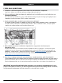
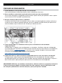
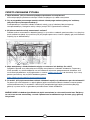
NOTE: Most newer PC cases include a CPU cut-out to allow access to the bottom of the motherboard.
If your case does not include a cut-out, you will need to remove your motherboard from the case prior
to installation. ELITE Series coolers come with the Intel mounting bracket pre-installed on the pump for
quick installation.
INTEL (All Sockets)
AMD AM5/AM4
AMD sTRX4
FINISHING UP YOUR INSTALLATION
FAQ

1
ENGLISH
INTEL
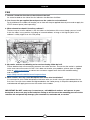
ELITE CAPELLIX
1
65 4 3 2 1
65 4 3 2 1
RGB HUB
FANS
B CA
D E F
G
H
I
LK
J
N O
M
QP
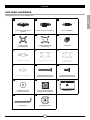
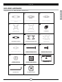
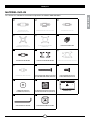
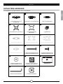
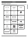
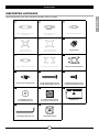
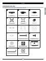
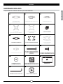
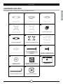
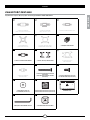
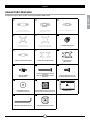
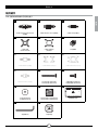
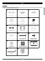
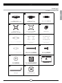
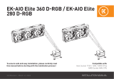
INCLUDED HARDWARE
Highlighted parts for Intel installation only
x4 INTEL 1200/1156/1155/1151/1150
STANDOFFS x4 INTEL 2066/2011-3/2011 STANDOFFS x4 INTEL 1700 STANDOFFS
x1 INTEL BACKPLATE
(1200/115X/1700 ONLY) x1 INTEL MOUNTING BRACKET
(PRE-INSTALLED) x4 THUMB NUTS
x4 AMD AM5/AM4 STANDOFFS x1 AMD AM5/AM4 MOUNTING BRACKET x1 AMD sTR4/sTRX4
MOUNTING BRACKET
x4 AMD sTR4/sTRX4 STANDOFFS x16 LONG FAN SCREWS (H100i/H115i)
x24 LONG FAN SCREWS (H150i/H170i) x8 RADIATOR SCREWS (H100i/H115i)
x12 RADIATOR SCREWS (H150i/H170i)
x8 WASHERS (H100i/H115i)
x12 WASHERS (H150i/H170i) x2 AF RGB ELITE FANS (H100i/H115i)
x3 AF RGB ELITE FANS (H150i/H170i) COMMANDER CORE
CAP REMOVAL TOOL x2 ALTERNATIVE PUMP CAP

2
D
CLGA 1700
BLGA 2011/
2011-3/2066
ALGA 1200/
1150/1151/
1155/1156
ENGLISH
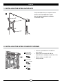
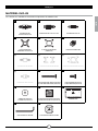
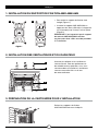
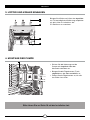
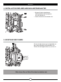
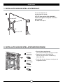
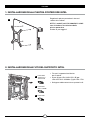
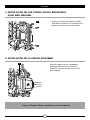
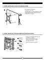
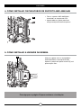
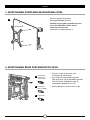
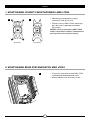
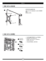
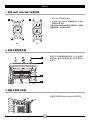
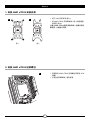
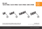
> Attach the provided Intel standoff for
your socket.
> Use (A) for LGA 1200/115X, (B) for
LGA 2011/2011-3/2066 or (C) for LGA 1700.
> Tighten all four standoffs until
firmly secured.
Adjust backplate for your required socket.
NOTE: Intel LGA 2066/2011-3/2011
do not require backplate installation.
Proceed to step 2.
2. INSTALLING THE INTEL STANDOFF SCREWS
1. INSTALLING THE INTEL BACKPLATE

3
K
N
M
L
F
ENGLISH
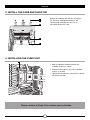
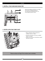
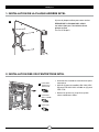
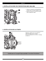
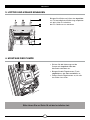
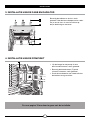
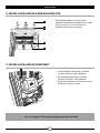
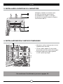
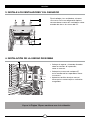
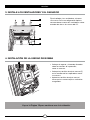
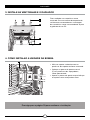
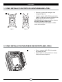
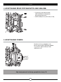
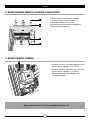
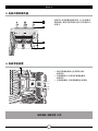
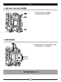
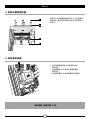
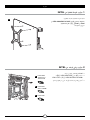
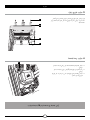
Attach the radiator and the fans as shown.
For the best cooling performance, we
recommend mounting the fans as an
air-intake to your PC case.
> Align the bracket and pump over the
standoff screws as shown.
> Attach the thumb nuts (F) to the standoff
screws as shown.
> Tighten the thumb nuts until all four corners
are firmly secured.
4. INSTALLING THE PUMP UNIT
3. INSTALL THE FANS AND RADIATOR
Please continue to Page 10 to continue your installation.

AMD AM5/AM4
ELITE CAPELLIX
1
65 4 3 2 1
65 4 3 2 1
RGB HUB
FANS
B
C
A
D
E
F
GH
I
LK
J
N O
M
QP
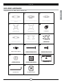
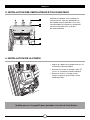
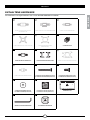
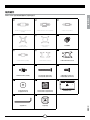
x4 INTEL 1200/1156/1155/1151/1150
STANDOFFS x4 INTEL 2066/2011-3/2011 STANDOFFS x4 INTEL 1700 STANDOFFS
x1 INTEL BACKPLATE
(1200/115X/1700 ONLY) x1 INTEL MOUNTING BRACKET
(PRE-INSTALLED) x4 THUMB NUTS
x4 AMD AM5/AM4 STANDOFFS x1 AMD AM5/AM4 MOUNTING BRACKET x1 AMD sTR4/sTRX4
MOUNTING BRACKET
x4 AMD sTR4/sTRX4 STANDOFFS x16 LONG FAN SCREWS (H100i/H115i)
x24 LONG FAN SCREWS (H150i/H170i) x8 RADIATOR SCREWS (H100i/H115i)
x12 RADIATOR SCREWS (H150i/H170i)
x8 WASHERS (H100i/H115i)
x12 WASHERS (H150i/H170i) x2 AF RGB ELITE FANS (H100i/H115i)
x3 AF RGB ELITE FANS (H150i/H170i) COMMANDER CORE
CAP REMOVAL TOOL x2 ALTERNATIVE PUMP CAP
INCLUDED HARDWARE
Highlighted parts for AMD AM5/AM4 installation only
ENGLISH

5
K
N
M
L
Figure 1 Figure 2
E H
Figure 1 Figure 2
ENGLISH
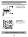
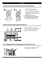
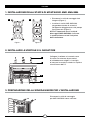
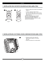
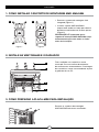
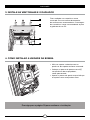
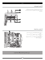
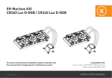
> Remove the integrated Intel mounting
bracket (Figure 1).
> Install the AMD AM5/AM4 bracket by
pushing both sides into the slot on the
pump until secure (Figure 2).
NOTE: It is important that the AMD AM5/
AM4 retention bracket be evenly secured on
all sides before installation.
Attach the radiator and the fans as shown.
For the best cooling performance, we
recommend mounting the fans as an
air-intake to your PC case.
2. INSTALL THE FANS AND RADIATOR
Remove the existing AMD AM5/AM4
mounting brackets shown.
3. PREPARE THE MOTHERBOARD FOR INSTALLATION
1. INSTALLING THE AMD AM5/AM4 MOUNTING BRACKET

6
G
FAlign the bracket with the AMD AM5/AM4
standoffs as shown. Tighten the thumb
nuts (F) until secure.
> Attach the provided AMD AM5/AM4
standoffs to the CPU socket.
> Tighten all four screws until firmly secure.
5. INSTALLING THE PUMP UNIT
4. INSTALLING THE AMD AM5/AM4 STANDOFF SCREWS
ENGLISH
Please continue to Page 10 to continue your installation.

7
ENGLISH
AMD sTRX4
ELITE CAPELLIX
1
65 4 3 2 1
65 4 3 2 1
RGB HUB
FANS
B
C
A
D
E
F
G
H
I
LK
J
N O
M
QP
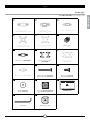
INCLUDED HARDWARE
Highlighted parts for AMD sTRX4 installation only
x4 INTEL 1200/1156/1155/1151/1150
STANDOFFS x4 INTEL 2066/2011-3/2011 STANDOFFS x4 INTEL 1700 STANDOFFS
x1 INTEL BACKPLATE
(1200/115X/1700 ONLY) x1 INTEL MOUNTING BRACKET
(PRE-INSTALLED) x4 THUMB NUTS
x4 AMD AM5/AM4 STANDOFFS x1 AMD AM5/AM4 MOUNTING BRACKET x1 AMD sTR4/sTRX4
MOUNTING BRACKET
x4 AMD sTR4/sTRX4 STANDOFFS x16 LONG FAN SCREWS (H100i/H115i)
x24 LONG FAN SCREWS (H150i/H170i) x8 RADIATOR SCREWS (H100i/H115i)
x12 RADIATOR SCREWS (H150i/H170i)
x8 WASHERS (H100i/H115i)
x12 WASHERS (H150i/H170i) x2 AF RGB ELITE FANS (H100i/H115i)
x3 AF RGB ELITE FANS (H150i/H170i) COMMANDER CORE
CAP REMOVAL TOOL x2 ALTERNATIVE PUMP CAP

8
J
Figure 1 Figure 2
E I
ENGLISH
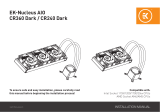
> Attach the provided AMD sTRX4 standoffs
to the CPU socket.
> Tighten all four standoff screws until
firmly secure.
> Remove the integrated Intel mounting
bracket (Figure 1).
> Install the AMD sTRX4 bracket by pushing
both sides into the slot on the pump until
secure (Figure 2).
NOTE: It is important that the AMD sTRX4
retention bracket be evenly secured on all
sides before installation.
2. INSTALLING THE AMD sTRX4 STANDOFF SCREWS
1. INSTALLING THE AMD sTRX4 MOUNTING BRACKET

9
K
N
L
M
ELITE CAPELLIX
13
F
ENGLISH
> Align the bracket and pump over the
standoff screws as shown.
> Attach the thumb nuts (F) to the standoff
screws as shown.
> Tighten the thumb nuts until all four corners
are firmly secured.
Attach the radiator and the fans as shown.
For the best cooling performance,
we recommend mounting the fans as
an air-intake to your PC case.
4. INSTALLING THE PUMP UNIT
3. INSTALL THE FANS AND RADIATOR
Please continue to Page 10 to continue your installation.

10
65 4 3 2 1
65 4 3 2 1
RGB HUB
FANS
3-PIN
65 4 3 2 1
65 4 3 2 1
RGB HUB
FANS
Figure 1 Figure 2 Figure 3
65 4 3 2 1
65 4 3 2 1
RGB HUB
FANS
65 4 3 2 1
65 4 3 2 1
RGB HUB
FANS
ENGLISH
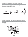
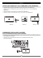
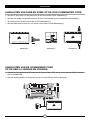
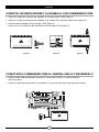
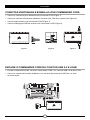
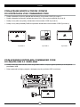
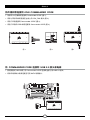
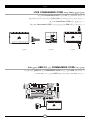
CONNECT COMMANDER CORE TO USB 2.0 HEADER AND POWER
CONNECT FANS AND PUMP TO iCUE COMMANDER CORE
> Connect pump 24-pin cable to your Commander CORE (Figure 1).
> Connect pump tach cable to the CPU_FAN header on your motherboard (Figure 2).
> Connect each fan to the Commander CORE (Figure 3).
> Connect each fan RGB lead to the Commander CORE (Figure 3).
> Using the attached USB cable, connect the Commander CORE to a motherboard
USB 2.0 header.
> Connect pump power cable to an available SATA power plug from your power supply.

11
ENGLISH
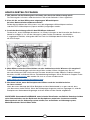
FAQ
1. How do I know the direction of the airflow of the fan?
An arrow located on the side of the fan indicates the direction of airflow.
2. Can I reuse the pre-applied thermal paste on the cooler for re-installation?
Re-installation of the cooler will require you to clean off the pre-applied thermal paste and re-apply the
XTM70 thermal paste (sold separately).
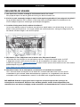
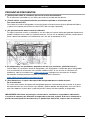
3. What orientation should I install my radiator?
The best way to install a radiator is with the tubes on the bottom of the case, though you can install
it with the tubes in any position, including an inverted radiator, as long as the highest point in the
radiator is visibly higher than the CPU pump.
4. My cooler and fans are blinking red or not functioning. What do I do?
Please double check all connections between the cooler and fans. Ensure that the cooler is updated
to the most recent firmware via iCUE. If this does not resolve your problems, please open a support
ticket at support.corsair.com or contact our customer support team for further troubleshooting
and assistance.
https://help.corsair.com/hc/en-us/requests/new
5. What should I do if my cooler backplate feels loose after installation?
It is common for your cooler backplate to feel loose after you install it into your motherboard for the
first time. Once you have seated and tightened down the cooler pump, it will pull the backplate to the
motherboard and apply pressure on the socket via the cooler.
IMPORTANT: Do NOT, under any circumstances, add additional washers and spacers to your
backplate to decrease play in the backplate. Doing so will increase the mounting pressure to the
retention kit and potentially damage your retention kit, motherboard, or socket.

FRANÇAIS
TABLE DES MATIÈRES
REMARQUE: La plupart des nouveaux boîtiers de PC comportent un accès facilité au processeur qui
permet d’accéder à la base de la carte mère. Si aucun accès n’est prévu sur votre boîtier, vous devrez
retirer votre carte mère du boîtier avant de procéder à l’installation. Les refroidisseurs ELITE Series sont
fournis avec le support de fixation Intel préinstallé sur la pompe afin de permettre une installation rapide.
INTEL (Tous Les Sockets)
AMD AM5/AM4
AMD sTRX4
ACHÈVEMENT DE VOTRE INSTALLATION
FOIRE AUX QUESTIONS

1
INTEL
FRANÇAIS
ELITE CAPELLIX
1
65 4 3 2 1
65 4 3 2 1
RGB HUB
FANS
B CA
D E F
G
H
I
LK
J
N O
M
QP
Les sections en surbrillance concernent uniquement l’installation Intel
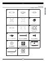
MATÉRIEL INCLUS
x4 ENTRETOISES INTEL
1200/1156/1155/1151/1150 x4 ENTRETOISES INTEL 2066/2011-3/2011 x4 ENTRETOISES INTEL 1700
x1 PLAQUE ARRIÈRE INTEL
(UNIQUEMENT 1200/115X/1700) x1 SUPPORT DE FIXATION INTEL
(PRÉINSTALLÉ) x4 ÉCROUS À SERRAGE À MAIN
x4 ENTRETOISES AMD AM5/AM4 x1 SUPPORT DE FIXATION AMD AM5/AM4 x1 SUPPORT DE FIXATION AMD sTR4/sTRX4
x4 ENTRETOISES AMD sTR4/sTRX4 x16 VIS DE VENTILATEUR LONGUES (H100i/H115i)
x24 VIS DE VENTILATEUR LONGUES (H150i/H170i) x8 VIS DE RADIATEUR (H100i/H115i)
x12 VIS DE RADIATEUR (H150i/H170i)
x8 RONDELLES (H100i/H115i)
x12 RONDELLES (H150i/H170i) x2 VENTILATEURS AF RGB ELITE (H100i/H115i)
x3 VENTILATEURS AF RGB ELITE (H150i/H170i) COMMANDER CORE
OUTIL DE RETRAIT DU CAPUCHON x2 CAPUCHONS ALTERNATIFS DE POMPE

2
D
CLGA 1700
BLGA 2011/
2011-3/2066
ALGA 1200/
1150/1151/
1155/1156
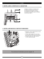
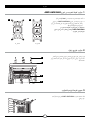
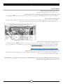
> Attachez les entretoises Intel fournies pour
votre prise.
> Utilisez (A) pour le modèle LGA 1200/115X,
(B) pour LGA 2011/2011-3/2066 ou (C) pour
LGA 1700.
> Serrez les quatre vis jusqu’à ce qu’elle
soient solidement fixées.
2. INSTALLATION DES VIS D’ENTRETOISE INTEL
Ajustez la plaque arrière pour votre socket.
REMARQUE: LGA 2066/2011-3/2011
ne nécessitent pas l’installation d’une
plaque arrière.
Passez à l’étape 2.
1. INSTALLATION DE LA PLAQUE ARRIÈRE INTEL
FRANÇAIS

3
K
N
M
L
F
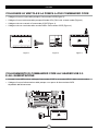
Veuillez passer à la page 10 pour procéder à la suite de l’installation.
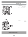
> Alignez le support et la pompe avec les vis
à entretoise comme indiqué.
> Attachez les écrous à serrage à main (F)
sur les vis à entretoise comme indiqué.
> Serrez les écrous à serrage à main
jusqu’à ce que les quatre coins soient
solidement fixés.
4. INSTALLATION DE LA POMPE
Attachez le radiateur et les ventilateurs,
comme illustré. Pour des performances
de refroidissement optimales, nous vous
recommandons d’installer les ventilateurs
comme une entrée d’air sur la tour
de votre ordinateur.
3. INSTALLATION DES VENTILATEURS ET DU RADIATEUR
FRANÇAIS

AMD AM5/AM4
ELITE CAPELLIX
1
65 4 3 2 1
65 4 3 2 1
RGB HUB
FANS
B
C
A
D
E
F
GH
I
LK
J
N O
M
QP
Les sections en surbrillance concernent uniquement l’installation AMD AM5/AM4
MATÉRIEL INCLUS
FRANÇAIS
x4 ENTRETOISES INTEL
1200/1156/1155/1151/1150 x4 ENTRETOISES INTEL 2066/2011-3/2011 x4 ENTRETOISES INTEL 1700
x1 PLAQUE ARRIÈRE INTEL
(UNIQUEMENT 1200/115X/1700) x1 SUPPORT DE FIXATION INTEL
(PRÉINSTALLÉ) x4 ÉCROUS À SERRAGE À MAIN
x4 ENTRETOISES AMD AM5/AM4 x1 SUPPORT DE FIXATION AMD AM5/AM4 x1 SUPPORT DE FIXATION AMD sTR4/sTRX4
x4 ENTRETOISES AMD sTR4/sTRX4 x16 VIS DE VENTILATEUR LONGUES (H100i/H115i)
x24 VIS DE VENTILATEUR LONGUES (H150i/H170i) x8 VIS DE RADIATEUR (H100i/H115i)
x12 VIS DE RADIATEUR (H150i/H170i)
x8 RONDELLES (H100i/H115i)
x12 RONDELLES (H150i/H170i) x2 VENTILATEURS AF RGB ELITE (H100i/H115i)
x3 VENTILATEURS AF RGB ELITE (H150i/H170i) COMMANDER CORE
OUTIL DE RETRAIT DU CAPUCHON x2 CAPUCHONS ALTERNATIFS DE POMPE

5
K
N
M
L
Figure 1 Figure 2
E H
Figure 1 Figure 2
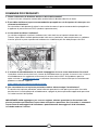
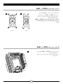
Retirez les supports de fixation
AMD AM5/AM4 existants indiqués.
3. PRÉPARATION DE LA CARTE MÈRE POUR L’INSTALLATION
Attachez le radiateur et les ventilateurs,
comme illustré. Pour des performances
de refroidissement optimales, nous vous
recommandons d’installer les ventilateurs
comme une entrée d’air sur la tour
de votre ordinateur.
2. INSTALLATION DES VENTILATEURS ET DU RADIATEUR
> Pour retirer le support de fixation Intel
intégré (Figure 1).
> Installez le support AMD AM5/AM4 en
appuyant des deux côtés dans le logement
sur la pompe jusqu’à ce qu’il soit en place
(Figure 2).
REMARQUE: Il est important que le support
de retenue AMD AM5/AM4 soit bien
en place des deux côtés avant de procéder
à l’installation.
1. INSTALLATION DU SUPPORT DE FIXATION AMD AM5/AM4
FRANÇAIS

6
G
F
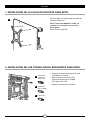
Veuillez passer à la page 10 pour procéder à la suite de l’installation.
Alignez le support avec les entretoises
AMD AM5/AM4 comme indiqué.
Serrez complètement les écrous à serrage
à main (F).
5. INSTALLATION DE LA POMPE
> Placez les entretoises AMD AM5/AM4
fournies dans le socket de processeur.
> Serrez les quatre vis jusqu’à ce qu’elle
soient solidement fixées.
4. INSTALLATION DES VIS D’ENTRETOISE AMD AM5/AM4
FRANÇAIS
La page est en cours de chargement...
La page est en cours de chargement...
La page est en cours de chargement...
La page est en cours de chargement...
La page est en cours de chargement...
La page est en cours de chargement...
La page est en cours de chargement...
La page est en cours de chargement...
La page est en cours de chargement...
La page est en cours de chargement...
La page est en cours de chargement...
La page est en cours de chargement...
La page est en cours de chargement...
La page est en cours de chargement...
La page est en cours de chargement...
La page est en cours de chargement...
La page est en cours de chargement...
La page est en cours de chargement...
La page est en cours de chargement...
La page est en cours de chargement...
La page est en cours de chargement...
La page est en cours de chargement...
La page est en cours de chargement...
La page est en cours de chargement...
La page est en cours de chargement...
La page est en cours de chargement...
La page est en cours de chargement...
La page est en cours de chargement...
La page est en cours de chargement...
La page est en cours de chargement...
La page est en cours de chargement...
La page est en cours de chargement...
La page est en cours de chargement...
La page est en cours de chargement...
La page est en cours de chargement...
La page est en cours de chargement...
La page est en cours de chargement...
La page est en cours de chargement...
La page est en cours de chargement...
La page est en cours de chargement...
La page est en cours de chargement...
La page est en cours de chargement...
La page est en cours de chargement...
La page est en cours de chargement...
La page est en cours de chargement...
La page est en cours de chargement...
La page est en cours de chargement...
La page est en cours de chargement...
La page est en cours de chargement...
La page est en cours de chargement...
La page est en cours de chargement...
La page est en cours de chargement...
La page est en cours de chargement...
La page est en cours de chargement...
La page est en cours de chargement...
La page est en cours de chargement...
La page est en cours de chargement...
La page est en cours de chargement...
La page est en cours de chargement...
La page est en cours de chargement...
La page est en cours de chargement...
La page est en cours de chargement...
La page est en cours de chargement...
La page est en cours de chargement...
La page est en cours de chargement...
La page est en cours de chargement...
La page est en cours de chargement...
La page est en cours de chargement...
La page est en cours de chargement...
La page est en cours de chargement...
La page est en cours de chargement...
La page est en cours de chargement...
La page est en cours de chargement...
La page est en cours de chargement...
La page est en cours de chargement...
La page est en cours de chargement...
La page est en cours de chargement...
La page est en cours de chargement...
La page est en cours de chargement...
La page est en cours de chargement...
La page est en cours de chargement...
La page est en cours de chargement...
La page est en cours de chargement...
La page est en cours de chargement...
La page est en cours de chargement...
La page est en cours de chargement...
La page est en cours de chargement...
La page est en cours de chargement...
La page est en cours de chargement...
La page est en cours de chargement...
La page est en cours de chargement...
La page est en cours de chargement...
La page est en cours de chargement...
La page est en cours de chargement...
La page est en cours de chargement...
La page est en cours de chargement...
La page est en cours de chargement...
La page est en cours de chargement...
La page est en cours de chargement...
La page est en cours de chargement...
La page est en cours de chargement...
La page est en cours de chargement...
-
 1
1
-
 2
2
-
 3
3
-
 4
4
-
 5
5
-
 6
6
-
 7
7
-
 8
8
-
 9
9
-
 10
10
-
 11
11
-
 12
12
-
 13
13
-
 14
14
-
 15
15
-
 16
16
-
 17
17
-
 18
18
-
 19
19
-
 20
20
-
 21
21
-
 22
22
-
 23
23
-
 24
24
-
 25
25
-
 26
26
-
 27
27
-
 28
28
-
 29
29
-
 30
30
-
 31
31
-
 32
32
-
 33
33
-
 34
34
-
 35
35
-
 36
36
-
 37
37
-
 38
38
-
 39
39
-
 40
40
-
 41
41
-
 42
42
-
 43
43
-
 44
44
-
 45
45
-
 46
46
-
 47
47
-
 48
48
-
 49
49
-
 50
50
-
 51
51
-
 52
52
-
 53
53
-
 54
54
-
 55
55
-
 56
56
-
 57
57
-
 58
58
-
 59
59
-
 60
60
-
 61
61
-
 62
62
-
 63
63
-
 64
64
-
 65
65
-
 66
66
-
 67
67
-
 68
68
-
 69
69
-
 70
70
-
 71
71
-
 72
72
-
 73
73
-
 74
74
-
 75
75
-
 76
76
-
 77
77
-
 78
78
-
 79
79
-
 80
80
-
 81
81
-
 82
82
-
 83
83
-
 84
84
-
 85
85
-
 86
86
-
 87
87
-
 88
88
-
 89
89
-
 90
90
-
 91
91
-
 92
92
-
 93
93
-
 94
94
-
 95
95
-
 96
96
-
 97
97
-
 98
98
-
 99
99
-
 100
100
-
 101
101
-
 102
102
-
 103
103
-
 104
104
-
 105
105
-
 106
106
-
 107
107
-
 108
108
-
 109
109
-
 110
110
-
 111
111
-
 112
112
-
 113
113
-
 114
114
-
 115
115
-
 116
116
-
 117
117
-
 118
118
-
 119
119
-
 120
120
-
 121
121
-
 122
122


Corsair iCUE H100i Series Manuel utilisateur
- Taper
- Manuel utilisateur
dans d''autres langues
- italiano: Corsair iCUE H100i Series Manuale utente
- português: Corsair iCUE H100i Series Manual do usuário
Documents connexes
-
Corsair iCUE Elite Capellix High Performance RGB Liquid CPU Cooler Manuel utilisateur
-
-
-
-
Autres documents
-
 ekwb EK-AIO Elite 360 D-RGB Guide d'installation
-
 ekwb EK-AIO 240 D-RGB Guide d'installation
-
Cooler Master PL240 Flux Manuel utilisateur
-
 ekwb EK-Nucleus AIO CR360 Lux D-RGB Guide d'installation
-
 ekwb EK-Nucleus AIO CR240 Lux D-RGB Guide d'installation
-
NZXT Kraken Elite 280 RGB Manuel utilisateur
-
-
 ekwb EK-Nucleus AIO CR360 Dark Guide d'installation
-
NZXT KRAKEN X Series Mode d'emploi
-
Alphacool Eisbaer AiO Manuel utilisateur


