United States Stove Company 4840 Le manuel du propriétaire
- Catégorie
- Poêles
- Taper
- Le manuel du propriétaire

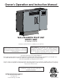
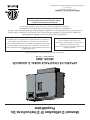
Owner’s Operation and Instruction Manual
SAFETY NOTICE: If this heater is not properly installed,
a house re may result. For your safety, follow the
installation instructions. Contact your local building or
re ofcials about obtaining a permit, restrictions and
installation requirements in your area.
CAUTION: Read All Instructions Carefully
Before Starting The Installation or Operating
This Heater. Improper Installation Could Void
Your Warranty!
Certied to ASTM E1509-12, Certied to ULC S627-00
UNITED STATES STOVE COMPANY
227 Industrial Park Road
P.O. Box 151
South Pittsburg, TN 37380
SAVE THIS MANUAL FOR FUTURE REFERENCE
THIS MANUAL WILL HELP YOU TO OBTAIN EFFICIENT, DEPENDABLE SERVICE FROM THE HEATER, AND ENABLE YOU
TO ORDER REPAIR PARTS CORRECTLY. KEEP IN A SAFE PLACE FOR FUTURE REFERENCE.
NOT RECOMMENDED AS PRIMARY HEAT SOURCE
852078K-0301H
A
10.52
WALL MOUNTED PELLET UNIT
MODEL 4840
U.S. Patent No. 9,752,778
French version is available for download from the United States Stove Company website: http://www.usstove.
com/ La version française est disponible pour téléchargement à partir du site United States Stove Company:
http://www.usstove.com/
U.S. Environmental Protection Agency
Certied to comply with 2015 particulate
emissions standards.

2
This manual describes the installation and operation of the U. S. Stove, 4840 wood heater. This heater meets the 2015 U.S.
Environmental protection agency’s crib wood emission limits for wood heaters sold after may 15, 2015. Under specic test
conditions this heater has been shown to deliver heat at rates ranging from 6,270 to 10,749 btu/hr.
• IMPORTANT: Read this entire manual before installing
and operating this product. Failure to do so may result in
property damage, bodily injury, or even death. Proper
installation of this heater is crucial for safe and efcient
operation. Never use make-shift compromises during the
installation.
• Before installing your heater, you must perform an initial
burn in an OUTSIDE environment. Follow the Start-Up
Procedure in the Operation section of this manual.
• This heater must be installed on an exterior wall to the
outside.
• Contact your local building ofcials to obtain a permit
and information on any additional installation restrictions
or inspection requirements in your area.
• Save these instructions.. This manual has important
operating and maintenance instructions that you will
need at a later time. Always follow the instructions in this
manual.
• This heater is designed and approved for premium
hardwood pellet fuel only. Any other type of fuel burned
in this heater will void the warranty and safety listing.
• Never use gasoline, gasoline-type lantern fuel, kerosene,
charcoal lighter uid, or similar ammable liquids to start
or “freshen up” a re in this heater. Keep all such liquids
well away from the heater while it is in use.
• A working smoke detector must be installed in the same
room as this product.
• Do not unplug the heater if you suspect a malfunction.
Turn the ON/OFF SWITCH to ”OFF’ and contact your
dealer.
• Do not operate your heater with the viewing or
combustion door open. The auger will not feed pellets
under these circumstances and a safety concern may
arise from sparks or fumes entering the room.
• Never disable or bypass the safety devices in this unit.
Doing so could result in damage to the unit or endanger
yourself or someone else.
• This wood heater needs periodic inspection and repair
for proper operation. It is against federal regulations to
operate this wood heater in a manner inconsistent with
operating instructions in this manual.
• Never try to repair or replace any part of the heater
unless instructions for doing so are given in this manual.
All other work should be done by a trained technician.
• Turn the heater OFF and allow to completely cool before
performing any maintenance.
• Disconnect the power cord before performing any
maintenance! NOTE: Turning the ON/OFF Switch to
”OFF” does not disconnect all power to the electrical
components of the heater.
• Ashes must be disposed in a metal container with a
tight tting lid. The closed container of ashes should be
placed on a non-combustible surface or on the ground,
well away from all combustible materials, pending nal
disposal.
• The exhaust system should be checked bi- monthly
during the burning season for any build-up of yash, soot
or creosote.
• HOT WHILE IN OPERATION. KEEP CHILDREN CLOTHING
AND FURNITURE AWAY. CONTACT MAY CAUSE
SKIN BURNS. Do not touch the hot surfaces of the
heater. Educate all children on the dangers of a
high-temperature heater. Young children should be
supervised when they are in the same room as the
heater.
• A power surge protector is required. This unit must be
plugged into a 110 - 120V, 60 Hz grounded electrical
outlet. Do not use an adapter plug or sever the
grounding plug. Do not route the electrical cord over
the heater. Do not route the cord in foot trafc areas or
pinch the cord under furniture.
• The heater will not operate during a power outage. If a
power outage does occur, check the heater for smoke
spillage and open a window if any smoke spills into the
room.
• Never block free airow through the open vents of the
unit.
• Keep foreign objects out of the hopper.
• The moving parts of this heater are propelled by high
torque electric motors. Keep all body parts away from
the auger while the heater is plugged into an electrical
outlet. These moving parts may begin to move at any
time while the heater is plugged in.
• Do not place clothing or other ammable items on or
near this heater.
• WARNING—DO NOT INSTALL THIS UNIT IN A SLEEPING
ROOM. CAUTION—The structural integrity of the mobile
home oor, wall, and ceiling/roof must be maintained.
• This appliance is not intended for commercial use.
• DO NOT INSTALL A FLUE DAMPER IN THE EXHAUST VENTING
SYSTEM OF THIS UNIT.
• DO NOT CONNECT THIS UNIT TO A CHIMNEY FLUE SERVING
ANOTHER APPLIANCE.
• DO NOT USE CHEMICALS OR FLUIDS TO START THE FIRE;
DO NOT BURN GARBAGE OR FLAMMABLE FLUIDS SUCH AS
GASOLINE, NAPHTHA OR ENGINE OIL.
• DO NOT CONNECT TO OR USE IN CONJUNCTION WITH
ANY AIR DISTRIBUTION DUCTWORK UNLESS SPECIFICALLY
APPROVED FOR SUCH INSTALLATIONS.
• The chimney connector shall not pass through an attic or
roof space, closet or similar concealed space, or a oor,
or ceiling. Where passage through a wall, or partition of
combustible construction is desired, the installation shall
conform to CAN/CSA-B365, Installation Code for Solid-
Fuel-Burning Appliances and Equipment.
Safety Precautions
Note: Register your product on line at www.usstove.com. See “Limited Warranty” section for specic warranty
information for your new purchase. Save your receipt with your records for any claims.

3
• BTU output will vary depending on the quality of fuel.
Use PFI listed fuels for the best results.
• Heating capacity will vary depending on oor plan
layout of your home, degree of insulation, and the
outside temperature.
• Pellet size may effect the actual rate of fuel feed
and burn times. Fuel feed rates may vary by as much
as 20%. Use PFI listed fuel for best results.
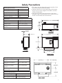
Heating Specications
Heat Output1 16,400 BTU/hr.
Heating Capacity2 500 - 1,000 sq. ft.
Fuel Burn Rate3 3/4 - 2 1/2 lbs./hr.
Burn Time (lowest setting) 35 hours
Hopper Capacity 28lbs
FRONT VIEW
TO VIEW
IE VIEW
22.50 [571.5]
4.50 [114.2]
36.00 [914.4]
22.25 [565.2]
12.43 [315.7]
1.84 [46.7]
APPROX.
16.92
APPROX.
35.87 [911]
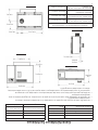
Dimensions
Height 27” [685.7 mm]
Width 36” [914.4 mm]
Depth of Unit 12.43” [315.77 mm]
Depth with Mounting Wall
Bracket
Approx. 14.27” [362.4 mm]
Product Weight 185 lbs
Intake/Exhaust Approximate Location Dimensions
Back Side Left Edge to
Center
29.34” [745.1 mm]
Back Side Top Edge to
Center
10.97” [278.7 mm]
Diameter of Intake\
Exhaust
5.25” [133.35 mm]
Diameter of Cut Out in
Exterior Wall
Refer for to Template
Safety Precautions
Electrical Specications
Electrical Rating 110-120 volt, 60Hz, 3.0Amp
Watts (operational) 175 approximately
Watts (igniter running) 425 approximately

4
FUEL CONSIDERATIONS
Your Pellet heater is designed to burn certied Premium Hardwood pellets that comply with Association of Pellet
Fuel Industries standards. Pellets that are soft, contain excessive amounts of loose sawdust, have been, or are
wet, will result in reduced performance. Failure to use proper fuel can affect the longevity of the appliance.
Smaller pellets could affect feed rates. Store your pellets in a dry area and well away from the heater. Do not use
grates or other methods of supporting the fuel. Burn fuel in burnpot without modication.
SAFETY AND COMPLIANCE
Your Pellet heater has been safety tested and listed to ASTM E 1509-04, UM-84 and ULC S627-00, by Intertek
Testing Services in Portland, Oregon, USA.
Pellet Fuel Institute (PFI) Premium Standards
Min. Density 40 lbs. per cubic ft.
Size ¼” to 5/16” diameter, length no greater than 1½”
Heat Output 8,200 BTU/lb
Moisture Content 8% by weight or less
Ash Content 1% by weight
Salt Content 300 parts per million or less
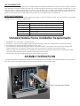
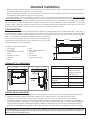
• WARNING! - Do not install in a sleeping room
• CAUTION! - The structural integrity of the mobile home oor, wall, and ceiling/roof must be maintained.
• The heater must be permanently attached to the wall.
• The heater must be electrically grounded to the steel chassis of the mobile home with 8 GA copper wire
using a serrated or star washer to penetrate paint or protective coating to ensure grounding.
• When moving your mobile home, the heater must be removed while the mobile home is being relocated.
After relocation, heater may be reinstalled and securely fastened.
• Check with your local building ofcials as other codes may apply.
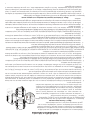
Insure that the ame impingement bafe is installed properly. If the bafe is not installed properly, push the plate
up in the void at an angle, rotate it to horizontal and place it on the metal stops.
Flame Impingement Bafe
Standard Mobile Home Installation Requirements
ASSEMBLY INSTRUCTIONS

5
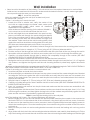
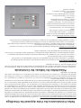
CLEARANCES TO COMBUSTIBLES
Combustible Clearance
Floor (Allow for brace) 8 inches [203mm]
Vent must meat
minimum ground
clearances
Left / Right 6 inches [152mm]
Ceiling (Allow for fuel
loading)
18 inches [457mm]
Mantle / Sill 11 inches [279mm]
Front 60 inches [1.5M]
6
[152]
39.
2 [51]
87 [91012]
2 [51]
Floor Protector
6
[152]
39.
2 [51]
87 [91012]
2 [51]
Floor Protector
6” [152mm]
18”
[457mm]
60”
[1.5M]
Floor Protector
Back Wall
Ceiling
• Read this entire manual before you install and use your pellet heater. Failure to follow instructions may result
in property damage, bodily injury, or even death!
• Before installing your heater, you must perform an initial burn in an OUTSIDE environment. Follow the Start-Up
Procedure in the Operation section of this manual.
Your pellet heater may be installed to code in either a conventional or mobile home (see SPECIAL MOBILE
HOME REQUIREMENTS). It is recommended that only a authorized technician install your heater, preferably a
National Fireplace Institute (NFI) certied specialist. This heater must be installed on an exterior wall to allow
exhaust venting to meet the minimum required clearances. Once the desired location is selected, and before
cutting a hole, check the outside of the structure for anything obstructing clearances to the exhaust vent. Also
clear away leaves, shrubs/bushes, or trees that may be around the exhaust outlet.
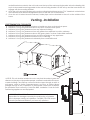
FLOOR PROTECTION
This heater must have a non-combustible oor protector (ember protection) installed beneath it if the oor is
of combustible material. If a oor pad is used, it should be UL listed or equal. The oor pad or non-combustible
surface should be large enough to extend a minimum of 6-inches [152mm] in front and 2-inches [51mm] on each
side of the heater. Canadian Installations require a minimum
of 450 mm [18”] beyond the front of the unit and 200mm [8”]
beyond each side of the unit. A Floor Protector of 1/4 inch thick
is recommended for this installation
GENERAL INSTALLATION NOTES
• Do not install heater where the exhaust will terminate in a window well or any opening below ground level.
• Special precautions may be required to prevent snow build-up within 12 inches of the air intake.
• Clearances around heater must provide adequate room for service, cleaning, and air circulation.
• Residential Garage Installation: The heater shall be located or protected so it is not subject to damage by
a moving vehicle. Use care when selecting a good location within the garage. DO NOT locate the heater
where the discharge air will be directed onto a nearby parked vehicle. DO NOT store containers of paint,
gasoline, or other ammable liquids in the same area as the heater, inside or outside the home or structure.
Standard Installation
Required Tools for installation:
• Venting Kit
• Power Drill
• 7/32” drill bit to drill pilot
holes
• Wrench / Socket.
• Hammer
• Knife
• Pen
• Non-combustible oor
protector
• Level
• Stud Finder
• Jig Saw / Hole Saw
ATTENTION: DO NOT vent under any porch, deck, awning, or in any semi enclosed or roofed area. Doing so may
result in unpredictable airow at the vent cap under certain conditions and can affect the performance of your stove, as
well as, other unforeseeable issues.

6
• Select a wall to the exterior of the building. This wall should have the required clearance to combustibles
inside and out as mentioned in this manual. Make certain that electrical wires, conduit, water or gas pipes
do not pass through the area you have selected.
Step: 1 Mount the wall plate
Note: Any material covering the wall (such as sheet rock) must
not exceed 5/8” 16 mm).
Option 1: Mounting on a wood-stud wall
1. Locate the studs in exterior wall. Verify the center of the
stud with an edge-to-edge stud nder. Mark center point
at predetermined height which meets all clearance
requirements of the appliance.
Note: Make sure that the opening for the exhaust thimble is
not to close to a stud in the wall before the hole is cut.
2. At the wall height that was determined in the previous step,
place a mid-sized nail through the center triangular shaped
hole of the mounting plate to hold it while the locations of
the mounting holes and the exhaust/intake through hole
are marked. Make sure that the wall mounting plate is ush
against the wall, then level the mounting plate and verify that
pilot holes are centered properly on the studs. Use a pencil to
mark the pilot hole locations, and intake/ exhaust through hole, then remove the mounting plate from the
wall.
3. Drill the four pilot holes to a depth of 2” (75 mm) using a 5/32” (3.96 mm) diameter drill bit.
4. Find the center of the through hole for the wall thimble and drill a pilot hole all the way through the wall to
the exterior with an installer bit. Use this hole as a center point to cut your hole through the exterior wall.
5. Carefully cut exhaust/intake through hole in exterior wall completely through to the outside. (SEE VENT
CLEARANCES SECTION TO INSURE PROPER INSTALLATION)
6. Install the wall thimble included with the vent kit to the manufactures instructions.
7. Realign the wall mount with the pilot holes and exhaust/intake through hole. Insert the four 1/4” x 2” lag bolts
with washers, and tighten the lag bolts until the wall mounting bracket is pulled rmly against the exterior
wall.
Warning: Avoid potential injuries or property damage! DO NOT over-tighten the lag bolts. THIS COULD POTENTIALLY
STRIP THE MOUNTING HOLES AND CAUSE THE BOLTS NOT TO HOLD CORRECTLY.
Option 2: Mounting on a solid concrete or concrete block wall
1. Level the wall plate and mark the hole locations.
2. At the wall height you determined in the previous step, place a small nail thru center triangle hole of bracket
and align the wall mount against the wall. Level bracket and verify that pilot holes are not located in the
mortar of the cinder blocks. Use a pencil to mark the pilot hole locations, and intake/exhaust thru hole then
remove the wall plate.
3. Drill pilot holes to a depth of 2” (75 mm) using a 5/32” (3.96 mm) diameter masonry drill bit.
4. Carefully cut intake/exhaust thru hole in exterior wall thru to the outside. (SEE VENT CLEARANCES SECTION TO
INSURE PROPER INSTALLATION)
5. Insert 1/4” concrete wall anchors into the pilot holes and make sure that the anchors are seated ush with
the concrete surface.
6. Align the wall plate with the anchors. Place washers over the screw holes in the wall plate, insert 1/4” x 2” lag
bolts through the washers, and then tighten the lag bolts until the washers are pulled rmly against the wall
plate and the wall mount is pulled rmly against the exterior wall.
Step: 2 Mounting the Heating Unit to the wall plate
Note: The Heating Unit is heavy. You will need assistance with this step.
1. Before hanging the unit on the wall bracket the exhaust/intake transition piece needs to be mounted on
the back of the unit. On the exhaust side of the unit there is a ring that is held on with four screws, it needs to
be removed so the transition piece can be mounted. Use the supplied Phillips head self-tapping screws to
attach the transition piece. Once the transition piece is mounted the ring on the outside of the unit can be
put back on.
2. After you have your hole cut and mounting bracket secured to the wall, the heating unit can hung on the
bracket.
3. Align /intake with the hole in the wall mounting bracket and thimble, and carefully insert heating unit. Tilt the
top of the heating unit towards the wall and lower onto the wall mounting bracket making sure that the right
5/8”
[16mm]
16”
[406mm]
3”
[75mm]
Wall Installation

7
IMPROPER INSTALLATION: The manufacturer will not be held
responsible for damage caused by the malfunction of a heater
due to improper venting or installation. Call (800) 750-2723 and/or
consult a professional installer if you have any questions.
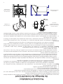
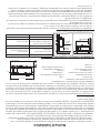
VENT TERMINATION CLEARANCES:
A. Minimum 4-foot [1.2m] clearance below or beside any door or window that opens.
B. Minimum 1-foot [0.3m]clearance above any door or window that opens.
C. Minimum 2-foot [0.6m] clearance from any adjacent building.
D. Minimum 7-foot [2.1m] clearance from any grade when adjacent to public walkways.
E. Minimum 2-foot [0.6m] clearance above any grass, plants, or other combustible materials.
F. Minimum 4-foot [1.2m] clearance from an forced air intake of any appliance.
G. Minimum 2-foot [0.6m] clearance below eves or overhang.
H. Minimum 1-foot [0.3m] clearance horizontally from combustible wall.
NOTICE: This unit shall be installed in such a way that the exhaust gases are
directed so they do not jeopardize people, overheat combustible structures,
or enter buildings. The chimney connector shall not pass through an attic or
roof space, closet or similar concealed space, or a oor, or ceiling. Where
passage through a wall, or partition of combustible construction is desired,
the installation shall conform to CAN/CSA-B365, Installation Code for Solid-
Fuel-Burning Appliances and Equipment.
A
6”
(152 mm)
24”
(609mm)
Venting -Installation
and left bracket mounted to the unit hooks over the top of the wall mounting bracket. Allow the Heating Unit
to pivot downward becoming parallel to the wall mounting bracket. Lift the unit up and the lower hooks will
engage with the mounting bracket.
4. Once the unit is securely hanging on the wall mounting bracket there are two 7/16” head bolt on the bottom
of the bracket that need to be tightened down to lock the unit to the bracket.
5. Once the unit is locked down the exhaust/ intake pipe can be attached to the unit on the outside of the
house.

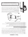
8
You must use the Duravent FasNSeal Concentric Vent System designed to work with this appliance from United
States Stove Company. DO NOT substitute other venting systems.
The 3” x 5” horizontal square termination kit (35CVS-KUS) includes:
1. 3” x 5” stove adapter
2. Adjustable Horizontal Square Cap 35CVS-HZSQ
3. Wall Thimble 35CVS-WT
Step 1) DirectVent Pro pipe and ttings are designed with special twistlock connections. To connect the venting
system to the appliance ue outlet, a twist-lock Appliance Adaptor is required. The adaptor will be
supplied for installation in the eld. Assemble the desired combination of Pipe Sections and Elbows to the
Appliance Adaptor.
Notes:
1. Twist-lock procedure: Line up locking lugs on male and female ends of pipe sections. Insert the male end of
pipe into the female end until the locking lugs are covered. Twist the female end clockwise an eighth of a
turn to lock sections together. Three screws are required to secure the joint, ensure they do not penetrate
the inner wall of the vent pipe.
2. Horizontal runs of vent pipe must be supported to prevent any downward sags. Horizontal pipe sections
should be supported at least every 4-feet. Wall Straps can be used for this purpose.
3. Seal all joints with high temperature silicone.
Step 2) With the appliance adaptor and pipe section attached to the appliance, slide the appliance into its
correct location, and mark the wall for a hole of the appropriate size. The center line of the pipe should
line up with the center of the hole. Cut and frame the hole in the exterior wall where the vent will be
terminated. A Wall Thimble is required.
Notes:
1. The horizontal run of venting must be level, or have a 1/4-inch rise for every 1-foot of run towards the
termination. Never allow the vent to run downward. A downward slope can trap heat and become a
possible re hazard.
2. The location of the Horizontal Vent Termination on an exterior wall must meet all local and national building
codes, and must not be easily blocked or obstructed. Termination clearances as shown in the VENT
TERMINATION CLEARANCES section.
A source of fresh air shall be provided when required. To ensure this make sure that the intake to the concentric
vent system is clear of all obstructions during use.
7
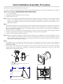
Figure 4
Figure 5
Figure 6
Notes:
(1) Twist-lock procedure: Line up
locking lugs on male and female ends
of pipe sections. Insert the male end
of pipe into the female end until the
locking lugs are covered. Twist the
female end clockwise an eighth of a
turn to lock sections together (Fig. 5).
Screws are not required to secure the
joint, but are acceptable provided they
do not penetrate the inner wall of the
vent pipe.
(2) Horizontal runs of vent pipe
must be supported to prevent any
downward sags. Horizontal pipe
sections should be supported at least
every 4-feet. Wall Straps can be
used for this purpose. Alternatively,
plumbers tape or other suitable
noncombustible material can be used
to support the vent pipe.
(3) DirectVent Pro venting requires no
appliance manufacturer.
Step 3. With the Appliance Adaptor
and Pipe Section attached to the
appliance, slide the appliance into its
correct location, and mark the wall
for a square hole of the appropriate
size. Refer to Table 1, page 8 for
the correct size square opening
appliance manufacturer’s clearance
requirements. The centerline of the
pipe should line up with the center
of the square hole (Fig. 6). Cut
and frame the square hole in the
exterior wall where the vent will
be terminated. A Wall Thimble or
Wall Firestop may be required by the
appliance manufacturer as additional
thermal protection for the wall. If the
MALE
END
FEMALE
END
SCREWS
OF HOLE
CENTER
L
C
Exterior Wall Thimble
Interior Wall Thimble
Main Thimble Assembly
A
10.52
5.85
5.10
5
6
3
2
1
8
7
4
6.66
7.64
.22
1
1
8
"
R
1
16
"
3
16
"
.19
DETAIL A
SCALE 1 : 1
ITEM
NO.
QTY
.
Description
Material
Thickness
Material
1
1
Vent Deflector
0.016
SS - 430 SS
2
1
Vent Base
0.016
SS - 430 SS
3
1
Vent Cover
0.016
SS - 430 SS
4
1
Outer Sleeve
0.018
ZA
5
1
Inner Sleeve
0.012
4S - 444 SS
6
1
Adapter Ring
0.018
GA - G90
7
4
SS Piercing Rivet - Clinch Range (.038-.063)
410 SS
8
19
SS Tubular Rivet - Clinch Range (.038-.063)
410 SS
D
E
F
C
1
2
B
A
3
2
1
5
C
D
A
B
A
1 / 1
1:6
SHEET NR.
SCALE
SHEETSIZE
CHECKED
REMARK
DESCRIPTION
PRODUCT LINE
DATE
DRAW.NR.
X-35CVS-HZSQ
AOstapenko
07/17/2013
TOOL.NUM.
ART.NR.
PROJECT FOLDER
C:\CAD\Projects\M&G DuraVent\Certification\CVS\
DMaxwell
ALL RIGHTS RESULTING FROM THIS DESIGN,
ARE RESERVED TO THE M&G GROUP
E
Units are inches
Tolerances
(unless otherwise specified)
Assemblies:
x/x +/- 1/8"
x.xxx +/- 0.125"
Angles: +/- 3°
4
Default
MATERIAL
3
See Parts List
CVS
DRAWN
DuraVent Inc.
Member of M&G GROUP
3x5" Dia Horizontal Square Termination
Certification Drawing
Exterior Wall Thimble
Duravent Fasnseal Concentric Vent System
Twistlock Procedure
Concentric Vent Attachment
Adjustable Horizontal Square Cap
Vent Installation/Assembly Procedure

9
HOW YOUR HEATER WORKS
Your pellet heater operates on a timer based auger fuel feed system, that is controlled by a digital circuit board.
The fuel is delivered from the auger into a burn pot, which is the vessel where the combustion process takes
place. Based upon the heat ranges (1-5), the heater will feed the appropriate amount of fuel to reach a set
temperature range. Note that the amount of heat produced by the heater is proportional to the rate of the fuel
that is burned. Your heater is equipped with an automatic ignition system that should ignite the fuel within 5-10
minutes from pressing the ON button. As pellets fall into the burn pot and ignite, outside air is drawn in to feed the
re by a combustion blower. The post combustion gases are then pulled through the heat exchanger as they are
traveling out the exhaust. As the heater warms up, room air is circulated around the heat exchanger by means
of a room air blower, distributing warm air into the room.
Because a forced draft pressure is required for the combustion process inside your heater, it is extremely important
that the exhaust system be properly maintained. And, that when operating your heater, you make sure that the
viewing and combustion doors are properly closed and/or sealed.
Turning the heater ON/OFF, as well as adjustments for the fuel feed rate is performed by pressing the appropriate
button(s) on the control panel which is located on the front, lower left-hand corner of your heater.
ON/OFF
• Pressing the “ON” button on the control panel will begin the start-up sequence for the heater. Fuel will begin
to feed through the auger feed system then ignite after approx. 5 minutes.
• Pressing the “OFF” button on the control panel will cause the heater to enter its shut-down sequence. The
fuel feed system will stop pulling fuel from the hopper and, once the re goes out and the heater cools
down, the fans will stop running.
HEAT RANGE
• Pressing the “Heat Range” arrows, up or down, will adjust the amount of fuel being delivered to the burn pot.
• The exhaust blower will start. Note that this appliance pulses the exhaust blower in order to achieve the
proper air to fuel ratio, and to also aid in the cleaning of the burn pot.
• Once the heater reaches a set temperature, the room fan will come on.
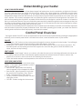
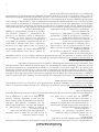
LIGHT (LED) INDICATORS
Heat Range LED - displays the selected heat setting.
Number “1” LED lights to display that there is power to
unit even if the heater is off.
• Door Sw LED - lights when front viewing
door is opened or if the hopper lid is raised.
• Press Sw LED - lights if pressure is lost inside
the combustion chamber. (See “Errors”)
• E LED - Operational Error (See “Errors”)
• ON LED - Flashes in start-up mode. On solid
during Run mode
• OFF LED - Flashes during shut down mode
Understanding your heater
Control Panel Overview

10
This heater is designed to burn only PFI Premium grade pellets. This appliance can also burn pellets rated as
standard after May 16, 2015
DO NOT BURN:
1. Garbage;
2. Lawn clippings or yard waste;
3. Materials containing rubber, including tires;
4. Materials containing plastic;
5. Waste petroleum products, paints or paint thinners,
or asphalt products;
6. Materials containing asbestos;
7. Construction or demolition debris;
8. Railroad ties or pressure-treated wood;
9. Manure or animal remains;
10. Salt water driftwood or other previously salt water
saturated materials;
11. Unseasoned wood; or
12. Paper products, cardboard, plywood, or
particleboard. The prohibition against burning
these materials does not prohibit the use of re
starters made from paper, cardboard, saw dust,
wax and similar substances for the purpose of
starting a re in an affected wood heater. Burning
these materials may result in release of toxic fumes
or render the heater ineffective and cause smoke.
UNIT PREPARATION
After properly installing your heater, you will need to attach the electrical cord to the right side blower housing
rst; then plug it into a 110-volt outlet (an outlet surge protector is highly recommended).
PERFORMING AN INITIAL BURN
You must perform an initial burn in this appliance before installing it in your home or garage. This process is to
ensure that the appliances is functioning correctly, to cure the high temperature paint and burn off any oil that is
present in the sheetmetal components of the combustion chamber. For the initial burn, only add a small amount
of fuel, approximately 4-5 lbs. or about the amount to ll a 2 lb. coffee can. Operate the appliance on the 3 or
4 heat setting for approximately 30 minutes to an hour. There will probably be a small amount of smoke or fumes
irradiating from the appliance during this process. Follow the Start-Up procedure below to begin your burn.
START-UP PROCEDURE
• Never use gasoline, gasoline-type lantern fuel, kerosene, charcoal lighter uid, or similar liquids to start or
“freshen up” a re in this heater. Keep all such liquids well away from the heater while it is in use.
1. Verify that the hopper is clean and free of foreign matter.
2. Fill the hopper with wood pellets; do not allow any part of the bag or any other foreign material into the
hopper, as this may jam the auger.
3. Ensure that all pellet matter is cleared from the hopper seating surface.
4. Close the hopper lid. The unit WILL NOT feed fuel with the hopper lid open.
5. Verify that there is no pellet fuel, ash, or foreign matter in the burn-pot before starting the appliance.
6. Make sure that the viewing door and combustion door is securely closed (the safety switch will not allow the
heater to feed fuel if they are left open.
7. Press the “ON” button on the control pad and set the “heat RANGE” to your desired setting. The ON light will
be ashing and the light corresponding with the heat setting will be light.
The heater will begin to feed fuel and the exhaust (draft) blower is running. Note that the exhaust blower is
pulsing. The auto-start ignitor will ignite the fuel in approximately 5-10 minutes. In the start-up mode, the “ON”
LED will ash until it reaches a factory preset temperature. At that point, the “ON” LED will come on solid and
the heater will begin to ramp up to your selected heat range. The Room Air Blower will not function until the
heater reaches a factory preset temperature. Attempts to achieve heat output rates that exceed heater design
specications can result in permanent damage to the heater.
SHUT DOWN PROCEDURE
Press the “OFF” button on the control pad to put the stove in shut down mode. At this time, the red light above
the OFF will blink and the “ON” light will go off. The auger will stop feeding pellets, but the distribution blower
and exhaust blower will continue to operate. When the internal temperature of the unit drops below the factory
preset temperature, the distribution blower and exhaust blower will cease to operate. The red light will then shut
off and the unit will be completely shut down. The hotter the unit is during its operation, the longer it will take for
the stove to complete the shut down cycle. If the stove stays on for more than 1 hour after pressing the “OFF”
button and you are sure that the re is out, the stove can be unplugged from the outlet. After approximately 10
seconds, the unit can be re-connected to the power source and the control board will be reset.
WARNING: Never shut down this unit by unplugging it from the power source.
Operation

11
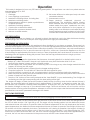
DAILY OPERATION
• Never place your hand near the auger while the heater is in operation.
• This unit should be lled when the hopper level drops below 3-inches.
• In the event of a power outage, the heater will not function. If the unit was “ON” when the power outage
occurred, one of the following will take place:
1. If the heater is still warm, it will resume feeding fuel and continue to operate normally. If the re has gone out,
you will have to press the “OFF” button and then the “ON” button again to begin a new start-up sequence.
2. If the heater has cooled-off, it will reset to its “OFF” condition. At this point, you may press the “ON” button
and the unit will begin a new start-up sequence. Make it a habit to empty the burn pot in these situations.
NOTE: The unit will also shut down in the event of an exhaust blower failure; if this is the case, the unit will not re-
start and you must contact Customer Service at (800) 750-2723.
The amount of visible smoke being produced can be an effective method of determining how efciently the
combustion process is taking place at the given settings. Visible smoke consist of unburned fuel and moisture
leaving your stove. Learn to adjust the air settings of your specic unit to produce the smallest amount of visible
smoke. Wood that has not been seasoned properly and has a high wood moisture content will produce excess
visible smoke and burn poorly.
SAFETY AND CONVENIENCE FEATURES
Your heater incorporates safety switches that helps ensure that everything is in proper working order before
feeding fuel to the burn pot. The heater will not operate if the viewing or combustion door is left open; or if the
exhaust blower fails or the exhaust system is blocked.
The RTD, Resistance Temperature Device, will prevent your heater from operating at abnormally high temperatures.
The heater has two over temperature limits. If the unit reaches the rst limit, it will reduce fuel consumption in
order to reduce temperatures. If the unit reaches the second limit, it will shut down and will need to be restarted.
Your heater also includes an auto-start igniter as a standard feature. The use of other re starter materials (wood
chips, starter gel, etc.) is not necessary. By simply pressing the “ON” button on the digital control panel, your
heater will begin to feed fuel and automatically start within 5 minutes.
This wood heater has a manufacturer-set minimum burn rate that must not be altered. It is against federal
regulations to alter this setting or otherwise operate this wood heater in a manner inconsistent with operating
instructions in this manual.
Operation

12
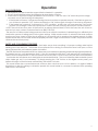
MAINTENANCE SCHEDULE
Use the following as a guide under average use conditions.
Gaskets around door and door glass should be inspected and repaired or replaced when necessary.
• Failure to clean and maintain this unit as indicated can result in poor performance, safety hazards and void
your warranty.
• Unplug your heater’s electrical cord prior to removing the back panel or opening the exhaust system for any
inspection, cleaning, or maintenance work.
• Never perform any inspections, cleaning, or maintenance on a hot heater.
• Do not operate heater with broken glass , leakage of ue gas may result.
EXHAUST SYSTEM
The by products of combustion contain small particles of y ash. Fly ash will collect in the exhaust venting
system and restrict the ow of ue gases. Incomplete combustion, such as during startup, shutdown, or incorrect
operation of the heater will lead to soot or creosote formation which will collect in the exhaust system and if
ignited, an extremely hot re could result. Therefore, it is important that the exhaust system be inspected and
cleaned at least bi-monthly during the burning season. Contact your local municipal or provincial re authority
for information on how to handle a re. Have a clearly understood plan to handle a re if one should ever occur.
Cleaning or monitoring the areas behind the front cleanout door should be done frequently to ensure minimum
y ash or soot/creosote build-up.
INTERIOR CHAMBERS
Periodically remove and clean the burn pot, ame impingement plate and the areas behind the cleanout door.
In particular, it is advisable to clean out the holes in the burn pot to remove any build up that may prevent air
from moving through the burn pot freely. As good practice, you should remove and clean the burn pot each
time you restart the heater, weekly or as needed as this ensures that the best efciency is achieved.
If a vacuum is used to clean your heater, we suggest using a vacuum designed for ash removal. Some regular
vacuum cleaner (i.e. shop vacs) may leak ash into the room.
ASH REMOVAL
Remove the ashes periodically to avoid unnecessary ash build up. Ash removal is as follows:
1. Let re burn out and allow unit cool to room temperature.
2. Clean the heat exchanger tubes (see Heat Exchanger Cleaning section) – Make sure Pellet Stove is at room
temperature before touching .
3. Open the ash pan door, remove the burn pot and empty into metal container.
4. Vacuum to remove ashes from the rebox.
5. BE SURE THAT ASHES ARE COOL TO THE TOUCH BEFORE VACUUMING. Some vacuum cleaners may leak ash
into the room. Your vacuum cleaner should have a special lter or bag to eliminate leakage.
6. Remove ash pan and dispose of ashes into metal container.
7. Reinstall ash pan.
8. Reinstall burn pot.
ASH DISPOSAL
Ashes should be placed in a metal container with a tight tting lid. The closed container of ashes should be
placed on a non-combustible oor or on the ground, well away from all combustible materials, pending nal
disposal. If the ashes are disposed of by burial in soil or otherwise locally dispersed, they should be retained in the
closed container until all cinders have been thoroughly cooled. Do not place other waste in the same container.
Maintenance
Daily Weekly Monthly or as needed
Burn Pot Stirred Empty
Combustion Chamber Brushed
Ashes Check Empty
Interior Chambers Vacuumed
Combustion Blower Blades Vacuumed / Brushed
Convection Blower Impeller Vacuumed / Brushed
Vent System Cleaned
Gaskets Inspected
Glass Wiped/Cleaned
Hopper (end of season) Emptied and vacuumed
Heat Exchanger Tubes Bi-Weekly

13
SMOKE AND CO MONITORS
Burning wood naturally produces smoke and carbon monoxide(CO) emissions. CO is a poisonous gas when
exposed to elevated concentrations for extended periods of time. While the modern combustion systems in
heaters drastically reduce the amount of CO emitted out the chimney, exposure to the gases in closed or conned
areas can be dangerous. Make sure your stove gaskets and chimney joints are in good working order and sealing
properly to ensure unintended exposure. It is recommended that you use both smoke and CO monitors in areas
having the potential to generate CO.
CHECK AND CLEAN THE HOPPER
Check the hopper periodically to determine if there is any sawdust or pellets that are sticking to the hopper
surface. Clean as needed.
DOOR AND GLASS GASKETS
Inspect the door’s and ash pan’s gaskets periodically. These may need to be removed to have frayed, broken,
or compacted gaskets replaced. Keep door, glass, and ash pan seals in good condition. This unit’s door uses a
3/8” diameter rope gasket.
BLOWER MOTORS
Clean the air holes on the motors of both the exhaust and distribution blowers annually. Remove the exhaust
blower from the exhaust duct and clean out the internal fan blades as part of your fall start-up.
PAINTED SURFACES
Painted surfaces may be wiped down with a damp cloth. If scratches appear, or you wish to renew your paint,
contact your Authorized pellet heater Dealer to obtain a can of suitable high-temperature paint.
GLASS
Cleaning - We recommend using a high quality glass cleaner. Should a buildup of creosote or carbon accumulate,
you may wish to use 000 steel wool and water to clean the glass. DO NOT use abrasive cleaners. DO NOT perform
the cleaning while the glass is HOT.
In the event you need to replace the glass, Do not attempt to operate the unit with broken glass. Replacement
glass may be purchased from your U.S. Stove Pellet Burning Room Heater Dealer. If glass is broken, follow these
removal procedures:
Replacement glass must be 0.197” thick tempered ceramic glass with a working service temperature of 1400
deg. F.
1. Remove the retainers and any broken glass or gasketing from the sealing face of the door.
2. Install a new glass gasket.
3. Re-install the retainers to hold the glass. Be careful not to over-tighten the screws for this could damage the
glass.
4. To replace the viewing door glass remove the back of the door and the insulation, then proceed as described
for the rebox door glass replacement.
DO NOT abuse the door glass by striking, slamming or similar trauma. Do not operate the stove with the glass
removed, cracked or broken.
FALL START UP
Prior to starting the rst re of the heating season, check the outside area around the exhaust and air intake
systems for obstructions including leaves, bushes/shrubs, and/or trees. Clean and remove any y ash from the
exhaust venting system. Clean any screens on the exhaust system and on the outside air intake pipe. Turn all of
the controls on and make sure that they are working properly. This is also a good time to give the entire heater
a good cleaning throughout.
SPRING SHUT DOWN
After the last burn in the spring, remove any remaining pellets from the hopper and the auger feed system.
Scoop out the pellets and then run the auger until the hopper is empty and pellets stop owing. Vacuum out
the hopper. Thoroughly clean the burn pot, and rebox. The exhaust system should be thoroughly cleaned. If
removing the unit for storage, store the heater in a dry location.
YEARLY SERVICING
A yearly servicing and cleaning by your Authorized pellet heater dealer is recommended. A fee may be charged
for this service.
Maintenance

14
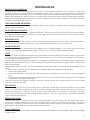
• Disconnect the power cord before performing any maintenance! NOTE: Switching the appliance to ”OFF”
does not disconnect all power to the electrical components of the heater.
• Never try to repair or replace any part of the heater unless instructions for doing so are given in this manual
or supplied from the factory. All other work should be done by a trained technician.
PROBLEM CAUSE: To rich air/fuel mixture
Orange, lazy ame, excessive fuel
build-up in the burn pot
• Clean out the burn pot and behind the cleanout door.
• Make sure that the combustion door is closed and sealed properly. If
not, adjust door catch and/or replace door gaskets.
• Check that the exhaust is clear of any obstructions. Clean as needed
• Check for proper seating of the burn pot.
PROBLEM CAUSE: Burn pot burns out of fuel
Fire goes out or heater shuts
down.
• Hopper is empty, rell the hopper.
• Loss of draft pressure. Make sure that the combustion door is closed
and sealed properly. If not, adjust door catch and/or replace door
gaskets. Check that the exhaust is clear of any obstructions. Clean as
needed.
• Make sure the viewing door and hopper lid is closed completely.
• Auger system is jammed or there is a “bridging” of the fuel in the
hopper, preventing fuel from owing into the auger feed system.
PROBLEM CAUSE: Auto-Start Igniter fails to ignite the fuel in the burn pot.
Heater does not start a re when
the “ON” button is pushed
• Turn the heater “OFF”. Clear the unburnt fuel from the burn pot and
try again.
• Check the pellet quality. Replace if moist, wet, or dirty.
• Loss of draft pressure. Make sure that the combustion door is closed
and sealed properly. If not, adjust door catch and/or replace door
gaskets. Check that the exhaust is clear of any obstructions. Clean as
needed.
• Check that the auto-start igniter is not blocked with ash or soot.
(The igniter is located behind the burn pot on the back wall of the
combustion chamber.)
• The auto-start igniter gets “red hot” during start-up. If you can not
visibly see the igniter glowing during start-up, then the igniter may
need to be replaced or there is a problem with the electrical control
system.
• Check for proper alignment between the burn pot and the igniter
tube.
PROBLEM CAUSE: Heater has reached the 2nd over temperature limit.
Heater enters shut-down mode • To much fuel in the burn pot. Restart heater after heater has cooled.
• RTD sensor in the room discharge air may be faulty causing the room
fan not to come on. Contact your dealer.
Trouble Shooting Errors

15
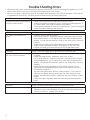
• Disconnect the power cord before performing any maintenance! NOTE: Switching the appliance to ”OFF”
does not disconnect all power to the electrical components of the heater.
• Never try to repair or replace any part of the heater unless instructions for doing so are given in this manual
or supplied from the factory. All other work should be done by a trained technician.
PROBLEM CAUSE:
The air inlet, burnpot, interior
combustion air chambers,
combustion blower, or exhaust
pipe are blocked with ash or
foreign material.
Follow all cleaning procedures in the maintenance section of the owner’s
manual.
Pressure switch hose or stove
attachment pipes for hose
are blocked.
Unhook air hose from the pressure switch and blow through it. If air ows
freely, the hose and tube are ne. If air will not ow through the hose, use
a wire coat hanger to clear the blockage.
The rebox is not properly sealed. Make sure the door is closed and that the gasket is in good shape.
Vent pipe is incorrectly installed Check to make sure vent pipe installation meets criteria in owner’s
manual.
The pressure switch wire
connections are bad.
Check the connectors that attach the wires to the pressure switch.
Combustion blower failure. With the stove on, check to see if the combustion blower is running. If it is
not, you will need to check for power going to the combustion blower. It
should be a full current. If there is power, the blower is bad.
Control board not sending power
to combustion blower.
If there is no current going to the combustion blower, check all wire
connections and fuse. If all wires are properly connected, you have a
bad control board.
Control board not sending power
to pressure switch.
There should be a 5-volt current (approximately) going to the air switch
after the stove has been on for 30 seconds.
Pressure switch has failed. To test the pressure switch, you will need to disconnect the air hose from
the body of the stove. With the other end still attached to the pressure
switch, very gently suck on the loose end of the hose (you may want to
remove the hose entirely
off the stove and the pressure switch rst and make sure it is clear). If you
hear a click, the air switch is working.
BE CAREFUL TOO MUCH VACUUM CAN DAMAGE THE AIR SWITCH!
Trouble Shooting Errors

16
C
O
V
E
R
P
L
A
T
E
1
PAD
1
P
ANEL, TOP, BOTTOM, AND BACK SIDE
1
P
ANEL, RIGHT SIDE
1
OSE
1
PRESSURE SWITCH/PC BOARD MOUNTING
1
N
TROLLER BOARD
1
E
SWITCH
1
1GNIRYTUAEB EKAT
N
T
1)DA-SVC53( TNEV TCERID
41
51
12
8
1
60
39
40
32
10
11
9
27
26
28
19
18
21
20
23
17
22
62
63
61
64
30
38
34
33
66
31
6
4
2
3
5
7
14
13
24
59
48
49
50
42
46
45
44
43
57
56
53
52
55
58
54
29
15
16
25
65
35
47
36
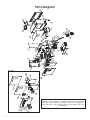
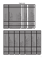
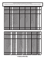
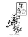
In order to maintain warranty, components must be
replaced using original manufacturers parts purchased
through your dealer or directly from the appliance
manufacturer. Use of third party components will void
the warranty.
Parts Diagram

17
Item Part No. Title Qty.
1 69800 Burn Chamber Enclosure Assembly 1
2 26195 Ignitor Cover 1
3 26196 Feed Tube Cover 2
4 80531 Rtd, Platinum 1
5 892004 Magnet 1
6 88180 Insulation, Right Sde- Chamber 1
7 26231 Rtd Mounting Bracket 1
8 891748 Burnpot Weldment 1
9 80619 Ignitor Cartridge 1
10 88118 Gasket, Ignitor Flange 1
11 69820 Ignitor Tube 1
12 892397 Burn Chamber Door 1
13 26175 Clean Door, Burn Chamber 1
14 89586 Auger Nipple 1
15 88184 Gasket Clean Door, Burn Chamber 1
16 88118 Gasket, Ignitor Flange 1
17 83529 Hairpin 1
18 891169 Hose, Heater 2
19 80529 Auger Motor 1
20 891132 Agitator Bushing 1
21 83534 Retaining Ring 1
22 892393 Auger 1
23 26237 Retaining Bracket, Auger Bushing 1
24 88033 Gasket - Combustion Chamber 1
25 69814 Door Switch Assembly 1
26 26204 Enclosure, Distribution Fan 1
27 80542 3" Double Centrifugal Blower - 125Cfm 1
28 26205 Enclosure Panel, Distribution Fan 1
29 26210 Exteners, Room Fans 2
30 26200 Panel, Main Cabinet Top And Side 1
31 88178 Insulation, Wrapped- Chamber 1
32 88179 Insulation, Left Side - Chamber 1
33 891148 Handle, Plastic 1
34 26217 Lid, Hopper 1
35 80462 Receptacle, 3 Prong 1
36 26229 Cover, Auger Access 1
37 69811 Door Switch Assembly 1
38 69808 Wall Mount Bracket Assembly 1
39 80573 Blower, Exhaust - 70 Cfm 1
40 88182 Main Gasket - Exhaust Blower 1
Item Part No. Title Qty.
41 892395 Right Door Assembly 1
42 26208 Left Front Door, Main 1
43 26199 Back Panel, Main Door 1
44 88181 Insulation, Left Front Door 1
45 26218 Door Spacer 2
46 892396 Weldment, Exhaust Louver 1
47 892174 Door Plunger 1
48 26216 Frame, Viewing Window 1
49 892215 Door Viewing Glass 1
50 88087 (4880) Gasket, Window, .125 X 1 W/Psa 1
51 892394 Left Door Assembly 1
52 26209 Front Door, Right 1
53 26214 Back Panel, Left Door 1
54 80555 Pwa, Display Board 1
55 69812 Assembly, Frame 01 1
56 89390A Rubber Grommet (3/8 Id) 1
57 26230 Pc Board Cover Plate 1
58 80550 Assy, Keypad 1
59 26185 Exhaust Panel, Top, Bottom, And Back
Side
1
60 26187 Exhaust Panel, Right Side 1
61 891121 Vaccum Hose 1
69809 Contol Board Assembly 1
62 26211 Bracket, Pressure Switch/Pc Board
Mounting
1
63 80545 Assy, Controller Board 1
64 80549 Pressure Switch 1
65 26360 Exhaust/Intake Beautyring 1
66 892208 Duravent Direct Vent (35Cvs-Ad) 1
892392 Flame Suppressor Plate
80650 Wire Harness Main
Parts List

18
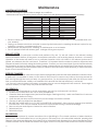
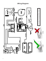
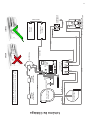
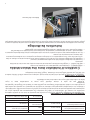
Wiring Diagram
CORRECT WRONG
Insure the wires are connected to the bottom
two prongs of the hopper switch as shown.

19
Notes

20
Service 01 Date:________________________
Engineer Name:_____________________________________
Company:__________________________________________
Telephone No.:______________________________________
Stove Inspected: Chimney Swept:
Items Replaced:____________________________________
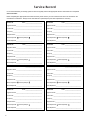
It is recommended that your heating system is serviced regularly and that the appropriate Service Interval Record is completed.
Service Provider:
Before completing the appropriate Service Record below, please ensure you have carried out the service as described in the
manufacturer’s instructions. Always use the manufacturer's specified spare part when replacement is necessary.
Service 02 Date:________________________
Engineer Name:_____________________________________
License No.:________________________________________ License No.:_______________________________________
Company:_________________________________________
Telephone No.:______________________________________
Stove Inspected: Chimney Swept:
Items Replaced:____________________________________
Service 03 Date:________________________
Engineer Name:_____________________________________
Company:__________________________________________
Telephone No.:______________________________________
Stove Inspected: Chimney Swept:
Items Replaced:____________________________________
Service 04 Date:________________________
Engineer Name:_____________________________________
Company:________________________________________
Telephone No.:______________________________________
Stove Inspected: Chimney Swept:
Items Replaced:____________________________________
Service 05 Date:________________________
Engineer Name:_____________________________________
Company:__________________________________________
Telephone No.:______________________________________
Stove Inspected: Chimney Swept:
Items Replaced:____________________________________
Service 06 Date:_______________________
Engineer Name:_____________________________________
Company:_________________________________________
Telephone No.:______________________________________
Stove Inspected: Chimney Swept:
Items Replaced:____________________________________
Service 07 Date:________________________
Engineer Name:_____________________________________
Company:__________________________________________
Telephone No.:______________________________________
Stove Inspected: Chimney Swept:
Items Replaced:____________________________________
Service 08 Date:_______________________
Engineer Name:_____________________________________
Company:_________________________________________
Telephone No.:______________________________________
Stove Inspected: Chimney Swept:
Items Replaced:____________________________________
License No.:_______________________________________ License No.:_______________________________________
License No.:_______________________________________ License No.:_______________________________________
License No.:_______________________________________ License No.:_______________________________________
Service Record
La page est en cours de chargement...
La page est en cours de chargement...
La page est en cours de chargement...
La page est en cours de chargement...
La page est en cours de chargement...
La page est en cours de chargement...
La page est en cours de chargement...
La page est en cours de chargement...
La page est en cours de chargement...
La page est en cours de chargement...
La page est en cours de chargement...
La page est en cours de chargement...
La page est en cours de chargement...
La page est en cours de chargement...
La page est en cours de chargement...
La page est en cours de chargement...
La page est en cours de chargement...
La page est en cours de chargement...
La page est en cours de chargement...
La page est en cours de chargement...
La page est en cours de chargement...
La page est en cours de chargement...
La page est en cours de chargement...
La page est en cours de chargement...
-
 1
1
-
 2
2
-
 3
3
-
 4
4
-
 5
5
-
 6
6
-
 7
7
-
 8
8
-
 9
9
-
 10
10
-
 11
11
-
 12
12
-
 13
13
-
 14
14
-
 15
15
-
 16
16
-
 17
17
-
 18
18
-
 19
19
-
 20
20
-
 21
21
-
 22
22
-
 23
23
-
 24
24
-
 25
25
-
 26
26
-
 27
27
-
 28
28
-
 29
29
-
 30
30
-
 31
31
-
 32
32
-
 33
33
-
 34
34
-
 35
35
-
 36
36
-
 37
37
-
 38
38
-
 39
39
-
 40
40
-
 41
41
-
 42
42
-
 43
43
-
 44
44


United States Stove Company 4840 Le manuel du propriétaire
- Catégorie
- Poêles
- Taper
- Le manuel du propriétaire