
ML11
Central locking system for a door
Installation and Operating Manual. . . . . . . . 3
Zentralverriegelung für eine Tür
Montage- und Bedienungsanleitung . . . . . 12
Verrouillage centralisé pour une
porte
Instructions de montage
et de service . . . . . . . . . . . . . . . . . . . . . . . . . 21
Cierre centralizado para una puerta
Instrucciones de montaje y de uso . . . . . . . 31
Fecho central para uma porta
Instruções de montagem e manual de
instruções . . . . . . . . . . . . . . . . . . . . . . . . . . .40
Chiusura centralizzata per una
porta
Istruzioni di montaggio e d’uso . . . . . . . . .49
Centrale vergrendeling voor een
deur
Montagehandleiding en
gebruiksaanwijzing . . . . . . . . . . . . . . . . . . .58
Centrallås til en dør
Monterings- og betjeningsvejledning. . . . 67
Centrallås för en dörr
Monterings- och bruksanvisning . . . . . . . . 76
Sentrallås for en dør
Monterings- og bruksanvisning . . . . . . . . . 85
Oven keskuslukitus
Asennus- ja käyttöohje . . . . . . . . . . . . . . . . 94
Центральный замок для двери
Инструкция по монтажу и
эксплуатации . . . . . . . . . . . . . . . . . . . . . . 103
Zamek centralny do drzwi
Instrukcja montażu i obsługi. . . . . . . . . . . 113
Centrálne zamykanie pre jedny
dvere
Návod na montáž a uvedenie
do prevádzky. . . . . . . . . . . . . . . . . . . . . . . 123
Centrální zamykání pro dveře
Návod k montáži a obsluze . . . . . . . . . . . 132
Központi reteszelés egy ajtóhoz
Szerelési és használati útmutató . . . . . . . 141
EN
DE
FR
ES
PT
IT
NL
DA
SV
NO
FI
RU
PL
SK
CS
HU
SAFETY SOLUTIONS
DOOR LOCKS
ML11-IO-16s.book Seite 1 Dienstag, 11. Juli 2017 9:09 09

ML11-IO-16s.book Seite 2 Dienstag, 11. Juli 2017 9:09 09

EN
ML11
3
Please read this instruction manual carefully before installation and first
use, and store it in a safe place. If you pass on the product to another
person, hand over this instruction manual along with it.
Table of contents
1 Explanation of symbols. . . . . . . . . . . . . . . . . . . . . . . . . . . . . . . . . . . . . . . . . . .4
2 Safety and installation instructions . . . . . . . . . . . . . . . . . . . . . . . . . . . . . . . . . .4
3 Scope of delivery . . . . . . . . . . . . . . . . . . . . . . . . . . . . . . . . . . . . . . . . . . . . . . .7
4 Accessories . . . . . . . . . . . . . . . . . . . . . . . . . . . . . . . . . . . . . . . . . . . . . . . . . . . .7
5 Intended use . . . . . . . . . . . . . . . . . . . . . . . . . . . . . . . . . . . . . . . . . . . . . . . . . . .7
6 Technical description . . . . . . . . . . . . . . . . . . . . . . . . . . . . . . . . . . . . . . . . . . . .7
7 Installing the central locking system. . . . . . . . . . . . . . . . . . . . . . . . . . . . . . . . .8
8 Warranty . . . . . . . . . . . . . . . . . . . . . . . . . . . . . . . . . . . . . . . . . . . . . . . . . . . . . 11
9 Disposal . . . . . . . . . . . . . . . . . . . . . . . . . . . . . . . . . . . . . . . . . . . . . . . . . . . . . . 11
10 Technical data . . . . . . . . . . . . . . . . . . . . . . . . . . . . . . . . . . . . . . . . . . . . . . . . . 11
ML11-IO-16s.book Seite 3 Dienstag, 11. Juli 2017 9:09 09

EN
Explanation of symbols ML11
4
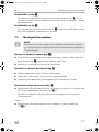
1 Explanation of symbols
!
!
A
I
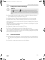
2 Safety and installation instructions
The manufacturer accepts no liability for damage in the following cases:
• Faulty assembly or connection
• Damage to the product resulting from mechanical influences and excess voltage
• Alterations to the product without express permission from the manufacturer
• Use for purposes other than those described in the operating manual
Please observe the prescribed safety instructions and stipulations from the
vehicle manufacturer and service workshops.
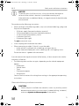
!
WARNING!
Inadequate supply cable connections could result in short circuits, which
could have as a consequence that:
• Cable fires occur
• The airbag is triggered
• Electronic control devices are damaged
• Electric functions fail (indicators, brake light, horn, ignition, lights)
WARNING!
Safety instruction: Failure to observe this instruction can cause fatal or
serious injury.
CAUTION!
Safety instruction: Failure to observe this instruction can lead to injury.
NOTICE!
Failure to observe this instruction can cause material damage and impair
the function of the product.
NOTE
Supplementary information for operating the product.
ML11-IO-16s.book Seite 4 Dienstag, 11. Juli 2017 9:09 09

EN
ML11 Safety and installation instructions
5
A
NOTICE!
To prevent the risk of short circuits, always disconnect the negative
terminal of the vehicle's electrical system before working on it.
If the vehicle has an additional battery, its negative terminal should also be
disconnected.
Please observe the following instructions:
• When working on the following cables, only use insulated cable lugs, plugs and
flat push-on receptacles:
– 30 (direct supply from positive battery terminal)
– 15 (connected positive terminal, behind the battery)
– 31 (return line from the battery, earth)
– L (indicator lights left)
– R (indicator lights right)
Do not use terminal strips.
• Use a crimping tool to connect the cables.
• When connecting to cable 31 (earth), screw the cable
– to the vehicle's earth bolt with a cable lug and a gear disc or
– to the sheet-metal bodywork with a cable lug and a self-tapping screw.
Ensure that there is a good earth connection.
If you disconnect the negative terminal of the battery, all data stored in the volatile
memories will be lost.
• The following data must be set again, depending on the vehicle equipment
options:
–Radio code
– Vehicle clock
–Timer
– On-board computer
– Seat position
You can find instructions for making these settings in the appropriate operating
instructions.
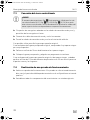
Observe the following installation instructions:
!
CAUTION!
• Secure the parts installed in the vehicle in such a way that they cannot
become loose under any circumstances (sudden braking, accidents)
and cause injuries to the occupants of the vehicle.
ML11-IO-16s.book Seite 5 Dienstag, 11. Juli 2017 9:09 09

EN
Safety and installation instructions ML11
6
• Secure any parts of the system covered by the bodywork in such a
manner that they cannot be come loose or damage other parts and
cables or impair vehicle functions (steering, pedals, etc).
• Always follow the safety instructions of the vehicle manufacturer.
Some work (e.g. on retention systems such as the AIRBAG etc.) may
only be performed by qualified specialists.
A
NOTICE!
• To prevent damage when drilling, make sure there is sufficient space
on the other side for the drill head to come out.
• Deburr all drill holes and treat them with a rust-protection agent.
Observe the following instructions when working with electrical parts:
A
NOTICE!
• When testing the voltage in electrical cables, only use a diode test
lamp or a voltmeter.
Test lamps with an illuminant take up voltages which are too high and
which can damage the vehicle's electronic system.
• When making electrical connections, ensure that:
– they are not kinked or twisted
– they do not rub on edges
– they are not laid in sharp edged ducts without protection.
• Insulate all connections.
• Secure the cables against mechanical wear with cable binders or insu-
lating tape, for example to existing cables.
ML11-IO-16s.book Seite 6 Dienstag, 11. Juli 2017 9:09 09

EN
ML11 Scope of delivery
7
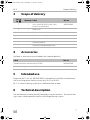
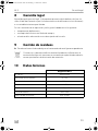
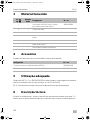
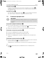
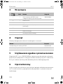
3Scope of delivery
4Accessories
Available as accessories (not included in the scope of delivery):
5 Intended use
MagicLock ML11 (ref. no. 9600001809) is intended for installation in combination
with an existing central locking system (e.g. ML22 or ML44).
ML 11 is a central locking system for an additional door or boot.
6 Technical description
The vehicle doors are automatically locked by using servo motors. The central lock-
ing systems are designed for vehicles with linkage locking systems.
No. in
fig. 1
Quantity Label Ref. no.
1 1 Servo motor ML3602 (Slave), 2 pin
for the rear vehicle door
9600000684
2 1 Metal hook
3 1 Perforated rail
4 Rubber cable bushing
5Cable
– – Fastening material
– – Installation and operating manual
Label Ref. no.
Universal wireless remote control MT400
9600000389
Universal sliding door contact ML10 9600001808
ML11-IO-16s.book Seite 7 Dienstag, 11. Juli 2017 9:09 09

EN
Installing the central locking system ML11
8
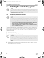
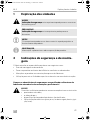
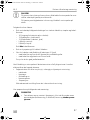
7 Installing the central locking system
I
7.1 Preparing installation location
I
This central locking system was developed for universal use and therefore the instal-
lation instructions cannot deal with vehicle-specific installation problems such as dis-
assembly of the bodywork or other work steps. In this case, please contact your
specialist workshop.
➤ Remove the bodywork.
➤ Remove the protective film, if there is any.
A
➤ Determine which possibilities exist for connecting the central locking system to
the locking mechanism on the lock.
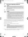
NOTE
If you do not have sufficient technical knowledge to install and connect
the components in vehicles, you should have a specialist install the cen-
tral locking system in your vehicle.
NOTE
• Select a convenient position for the servo motors close to the locking
pin that connects the locking button with the door lock. The move-
ment directions of servo motor and locking button or locking lever
must run parallel.
• Ensure that the window panel and the window regulator mechanism
do not touch the servo motor when opening and closing.
• If the installation position is in a door cut-out, use the perforated plate
rail for fitting the servo motor.
NOTICE!
The protective film prevents condensation from forming on the door or
boot covering and damaging them. For this reason, the protective film
must be glued on again undamaged after the installation has been com-
pleted.
ML11-IO-16s.book Seite 8 Dienstag, 11. Juli 2017 9:09 09

EN
ML11 Installing the central locking system
9
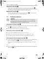
Possibility A see fig. 3
A locking button (fig. 4 1) is already available in the door or boot. The servo
motor is connected to this locking button with the help of a connection rod and
terminal block.
Possibility B see fig. 3
There is a locking lever (fig. 3 2) on the lock with a free eye in which the lock is
locked and unlocked.
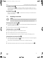
7.2 Installing servo motor
I
Attaching to door panel (fig. 4)
➤ Use the drill template (fig. 2) for an installation position behind the door panel
and drill two holes of Ø 5 mm.
➤ Screw on the servo motor using the self-tapping screws.
Attaching in door cut-out (fig. 5)
➤ Adjust the perforated plate rail to the door cut-out.
➤ Drill two holes of Ø 3 mm to attach the perforated rail.
➤ Screw on the perforated rail and servo motor using the self-tapping screws.
Attaching the connection rod (fig. 4)
➤ Hook the connection rod into the servo motor and connect it to the locking but-
ton using the terminal block (fig. 4 A).
Servo motor and locking button must be in the “unlocked” position.
or
➤ Hook the connection rod into the servo motor and the locking lever (fig. 4 B).
NOTE
Ensure that the servo motor and the locking button or the locking lever
are in the "unlocked" position when adjusting the connection rod.
ML11-IO-16s.book Seite 9 Dienstag, 11. Juli 2017 9:09 09

EN
Installing the central locking system ML11
10
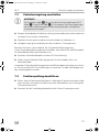
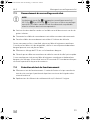
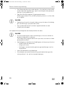
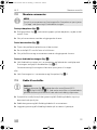
7.3 Connecting the central locking system
A
➤ Crimp both circular sleeves to the green and blue connection cable and apply
the insulation sleeves.
➤ Connect the green and blue connection cable to the servo motor.
➤ Route the green and blue connection cable into the interior of the vehicle.
Use the existing rubber bushing for this if possible.
If no original rubber bushing is available, check whether dummy plugs for a cable
bushing are available.
➤ Apply the dummy plug with a Ø 10-mm drill hole.
➤ Insert the rubber cable bushing and glue this with super glue.
If neither original rubber bushing nor dummy plug is available, Ø 10 mm drill holes
offset by approx. 50 mm must be drilled between the door or boot and the rails.
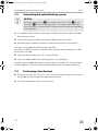
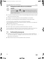
7.4 Performing a function test
➤ Perform a function test. If this test is not successful, adjust the position of the ter-
minal block on the linkage of the opening mechanism.
➤ Put all panelling back where it was originally.
NOTICE!
The circuit diagram (fig. 6) only applies to the ML22 (fig. 6 B) and
ML44 (fig. 6 A) central locking systems. For other central locking sys-
tems the motor wiring must be first determined from the corresponding
circuit diagrams.
ML11-IO-16s.book Seite 10 Dienstag, 11. Juli 2017 9:09 09

EN
ML11 Warranty
11
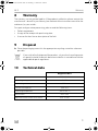
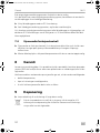
8Warranty
The statutory warranty period applies. If the product is defective, please contact the
manufacturer's branch in your country (see the back of the instruction manual for the
addresses) or your retailer.
For repair and guarantee processing, please send the following items:
• Defect components
• A copy of the receipt with purchasing date
• A reason for the claim or description of the fault
9Disposal
➤ Place the packaging material in the appropriate recycling waste bins wherever
possible.
M
If you wish to finally dispose of the product, ask your local recycling centre
or specialist dealer for details about how to do this in accordance with the
applicable disposal regulations.
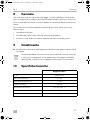
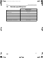
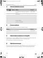
10 Technical data
MagicLock ML11
Ref. no.: 9600001809
Operating voltage: 9 – 15 V
Input voltage: 12 Vg
Current consumption: Max. 5 A
Operating temperature: –40 to +85 °C
Tensile force: max. 24 N
Adjustment travel of the servo motors: max. 20 mm
ML11-IO-16s.book Seite 11 Dienstag, 11. Juli 2017 9:09 09

DE
ML11
12
Bitte lesen Sie diese Anleitung vor Einbau und Inbetriebnahme sorgfältig
durch und bewahren Sie sie auf. Geben Sie sie im Falle einer Weitergabe
des Produktes an den Nutzer weiter.
Inhaltsverzeichnis
1 Erklärung der Symbole . . . . . . . . . . . . . . . . . . . . . . . . . . . . . . . . . . . . . . . . . .13
2 Sicherheits- und Einbauhinweise . . . . . . . . . . . . . . . . . . . . . . . . . . . . . . . . . .13
3 Lieferumfang . . . . . . . . . . . . . . . . . . . . . . . . . . . . . . . . . . . . . . . . . . . . . . . . . .16
4 Zubehör. . . . . . . . . . . . . . . . . . . . . . . . . . . . . . . . . . . . . . . . . . . . . . . . . . . . . .16
5 Bestimmungsgemäßer Gebrauch . . . . . . . . . . . . . . . . . . . . . . . . . . . . . . . . .16
6 Technische Beschreibung . . . . . . . . . . . . . . . . . . . . . . . . . . . . . . . . . . . . . . .16
7 Zentralverriegelung montieren . . . . . . . . . . . . . . . . . . . . . . . . . . . . . . . . . . .17
8 Gewährleistung. . . . . . . . . . . . . . . . . . . . . . . . . . . . . . . . . . . . . . . . . . . . . . . 20
9 Entsorgung . . . . . . . . . . . . . . . . . . . . . . . . . . . . . . . . . . . . . . . . . . . . . . . . . . 20
10 Technische Daten . . . . . . . . . . . . . . . . . . . . . . . . . . . . . . . . . . . . . . . . . . . . . 20
ML11-IO-16s.book Seite 12 Dienstag, 11. Juli 2017 9:09 09

DE
ML11 Erklärung der Symbole
13
1 Erklärung der Symbole
!
!
A
I
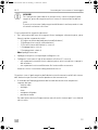
2 Sicherheits- und Einbauhinweise
Der Hersteller übernimmt in folgenden Fällen keine Haftung für Schäden:
• Montage- oder Anschlussfehler
• Beschädigungen am Produkt durch mechanische Einflüsse und Über-
spannungen
• Veränderungen am Produkt ohne ausdrückliche Genehmigung vom Hersteller
• Verwendung für andere als die in der Anleitung beschriebenen Zwecke
Beachten Sie die vom Fahrzeughersteller und vom Kfz-Handwerk
vorgeschriebenen Sicherheitshinweise und Auflagen!
!
WARNUNG!
Unzureichende Leitungsverbindungen können zur Folge haben, dass
durch Kurzschluss
• Kabelbrände entstehen,
• der Airbag ausgelöst wird,
• elektronische Steuerungseinrichtungen beschädigt werden,
• elektrische Funktionen ausfallen (Blinker, Bremslicht, Hupe, Zündung,
Licht).
WARNUNG!
Sicherheitshinweis: Nichtbeachtung kann zu Tod oder schwerer
Verletzung führen.
VORSICHT!
Sicherheitshinweis: Nichtbeachtung kann zu Verletzungen führen.
ACHTUNG!
Nichtbeachtung kann zu Materialschäden führen und die Funktion des
Produktes beeinträchtigen.
HINWEIS
Ergänzende Informationen zur Bedienung des Produktes.
ML11-IO-16s.book Seite 13 Dienstag, 11. Juli 2017 9:09 09

DE
Sicherheits- und Einbauhinweise ML11
14
A
ACHTUNG!
Klemmen Sie wegen der Kurzschlussgefahr vor Arbeiten an der Fahrzeug-
elektrik immer den Minuspol ab.
Bei Fahrzeugen mit Zusatzbatterie müssen Sie an dieser ebenfalls den
Minuspol abklemmen.
Beachten Sie deshalb folgende Hinweise:
• Verwenden Sie bei Arbeiten an den folgenden Leitungen nur isolierte Kabel-
schuhe, Stecker und Flachsteckhülsen:
– 30 (Eingang von Batterie Plus direkt)
– 15 (Geschaltetes Plus, hinter Batterie)
– 31 (Rückleitung ab Batterie, Masse)
– L (Blinkerleuchten links)
– R (Blinkerleuchten rechts)
Verwenden Sie keine Lüsterklemmen.
• Verwenden Sie eine Krimpzange zum Verbinden der Kabel.
• Schrauben Sie das Kabel bei Anschlüssen an Leitung 31 (Masse)
– mit Kabelschuh und Zahnscheibe an eine fahrzeugeigene Masseschraube
oder
– mit Kabelschuh und Blechschraube an das Karosserieblech.
Achten Sie auf eine gute Masseübertragung!
Beim Abklemmen des Minuspols der Batterie verlieren alle flüchtigen Speicher der
Komfortelektronik ihre gespeicherten Daten.
• Folgende Daten müssen Sie je nach Fahrzeugausstattung neu einstellen:
–Radiocode
–Fahrzeuguhr
– Zeitschaltuhr
– Bordcomputer
– Sitzposition
Hinweise zur Einstellung finden Sie in der jeweiligen Bedienungsanleitung.
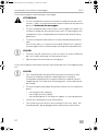
Beachten Sie folgende Hinweise bei der Montage:
!
VORSICHT!
• Befestigen Sie die im Fahrzeug montierten Teile so, dass sie sich unter
keinen Umständen (scharfes Abbremsen, Verkehrsunfall) lösen und zu
Verletzungen der Fahrzeuginsassen führen können.
ML11-IO-16s.book Seite 14 Dienstag, 11. Juli 2017 9:09 09

DE
ML11 Sicherheits- und Einbauhinweise
15
• Befestigen Sie verdeckt unter Verkleidungen anzubringende Teile des
Systems so, dass sie sich nicht lösen oder andere Teile und Leitungen
beschädigen und keine Fahrzeugfunktionen (Lenkung, Pedale usw.)
beeinträchtigen können.
• Beachten Sie immer die Sicherheitshinweise des Fahrzeugherstellers.
Einige Arbeiten (z. B. an Rückhaltesystemen wie Airbag usw.) dürfen
nur von geschultem Fachpersonal durchgeführt werden.
A
ACHTUNG!
• Achten Sie beim Bohren auf ausreichenden Freiraum für den Bohrer-
austritt, um Schäden zu vermeiden.
• Entgraten Sie jede Bohrung und behandeln Sie diese mit Rostschutz-
mittel.
Beachten Sie folgende Hinweise bei der Arbeit an elektrischen Teilen:
A
ACHTUNG!
• Benutzen Sie zum Prüfen der Spannung in elektrischen Leitungen nur
eine Diodenprüflampe oder ein Voltmeter.
Prüflampen mit einem Leuchtkörper nehmen zu hohe Ströme auf,
wodurch die Fahrzeugelektronik beschädigt werden kann.
• Beachten Sie beim Verlegen der elektrischen Anschlüsse, dass diese
– nicht geknickt oder verdreht werden,
– nicht an Kanten scheuern,
– nicht ohne Schutz durch scharfkantige Durchführungen verlegt
werden.
• Isolieren Sie alle Verbindungen und Anschlüsse.
• Sichern Sie die Kabel gegen mechanische Beanspruchung durch
Kabelbinder oder Isolierband, z. B. an vorhandenen Leitungen.
ML11-IO-16s.book Seite 15 Dienstag, 11. Juli 2017 9:09 09

DE
Lieferumfang ML11
16
3 Lieferumfang
4Zubehör
Als Zubehör erhältlich (nicht im Lieferumfang enthalten):
5 Bestimmungsgemäßer Gebrauch
MagicLock ML11 (Art.-Nr. 9600001809) ist für den Einbau in Kombination mit einer
bestehenden Zentralverriegelung (z. B. ML22 oder ML44) vorgesehen.
ML 11 ist eine Zentralverriegelung für eine zusätzliche Tür oder Heckklappe.
6 Technische Beschreibung
Durch den Einsatz von Stellmotoren werden automatisch die Fahrzeugtüren ver-
riegelt. Die Zentralverriegelungen sind ausgelegt für Fahrzeuge mit Gestänge-
Schließsystem.
Nr. in
Abb. 1
Menge Bezeichnung Art.-Nr.
1 1 Stellmotor ML3602 (Slave), 2-polig
für die hintere Fahrzeugtür
9600000684
2 1 Metallhaken
3 1 Lochschiene
4 Kabeldurchführungsgummi
5Kabel
– – Befestigungsmaterial
– – Montage- und Bedienungsanleitung
Bezeichnung Art.-Nr.
Universelle Funk-Fernbedienung MT400
9600000389
Universal Schiebetürkontakt ML10 9600001808
ML11-IO-16s.book Seite 16 Dienstag, 11. Juli 2017 9:09 09

DE
ML11 Zentralverriegelung montieren
17
7 Zentralverriegelung montieren
I
7.1 Montageort vorbereiten
I
Diese Zentralverriegelung wurde für den universellen Einsatz entwickelt und daher
kann in der Einbauanleitung nicht auf fahrzeugspezifische Einbauprobleme wie z. B.
die Demontage der Verkleidung oder andere Arbeitsschritte, eingegangen werden.
In diesem Fall wenden Sie sich bitte an Ihre Fachwerkstatt.
➤ Entfernen Sie die Verkleidung.
➤ Ziehen Sie die evtl. vorhandene Schutzfolie vorsichtig ab.
A
➤ Stellen Sie fest, welche Möglichkeiten bestehen, um die Zentralverriegelung an
den Verriegelungsmechanismus des Schlosses anzuschließen.
HINWEIS
Wenn Sie nicht über ausreichende technische Kenntnisse für das
Einbauen und Anschließen von Komponenten in Fahrzeugen verfügen,
sollten Sie sich die Zentralverriegelung von einem Fachmann ins Fahr-
zeug einbauen lassen.
HINWEIS
• Wählen Sie eine günstige Position für die Stellmotoren in der Nähe
der Verriegelungsstange, die den Verriegelungsknopf mit dem Tür-
schloss verbindet. Die Bewegungsrichtungen vom Stellmotor und
Verriegelungsgestänge bzw. Verriegelungshebel müssen parallel
verlaufen.
• Achten Sie darauf, dass Fensterscheibe und Mechanismus des
Fensterhebers beim Öffnen und Schließen nicht vom Stellmotor
berührt werden.
• Liegt die gefundene Einbauposition in einem Türausschnitt, verwen-
den Sie zur Montage des Stellmotors die Lochblechschiene.
ACHTUNG!
Die Schutzfolie verhindert, dass sich Kondenswasser an der Tür- bzw.
Heckklappenverkleidung niederschlägt und diese beschädigt. Aus
diesem Grund muss die Schutzfolie nach Beendigung des Einbaus
unbeschädigt wieder eingeklebt werden.
ML11-IO-16s.book Seite 17 Dienstag, 11. Juli 2017 9:09 09

DE
Zentralverriegelung montieren ML11
18
Möglichkeit A siehe Abb. 3
In der Tür bzw. Heckklappe ist schon ein Verriegelungsgestänge (Abb. 4 1)
vorhanden. An diesem Verriegelungsgestänge wird der Stellmotor mit Hilfe des
Verbindungsgestänges und des Klemmblocks angeschlossen.
Möglichkeit B siehe Abb. 3
Am Schloss befindet sich ein Verriegelungshebel (Abb. 3 2) mit einer freien
Öse, wodurch das Schloss ver- und entriegelt wird.
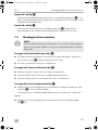
7.2 Stellmotor montieren
I
Befestigung am Türblech (Abb. 4)
➤ Verwenden Sie bei einer Einbauposition hinter dem Türblech die Bohrschablone
(Abb. 2) und bohren Sie zwei Löcher von Ø 5 mm.
➤ Schrauben Sie den Stellmotor mit den Blechschrauben an.
Befestigung im Türausschnitt (Abb. 5)
➤ Passen Sie die Lochblechschiene an den Türausschnitt an.
➤ Bohren Sie zur Befestigung der Lochschiene zwei Löcher von Ø 3 mm.
➤ Schrauben Sie Lochschiene und Stellmotor mit den Blechschrauben an.
Befestigung des Verbindungsgestänges (Abb. 4)
➤ Haken Sie das Verbindungsgestänge in den Stellmotor ein und verbinden Sie es
mittels Klemmblock (Abb. 4 A) mit dem Verriegelungsgestänge.
Stellmotor und Verriegelungsgestänge müssen dabei in Position „Entriegelt“
stehen.
oder
➤ Haken Sie das Verbindungsgestänge in den Stellmotor und den Verriegelungs-
hebel (Abb. 4 B) ein.
HINWEIS
Achten Sie darauf, dass sich der Stellmotor und das Verriegelungs-
gestänge oder der Verriegelungshebel beim Anpassen des Verbin-
dungsgestänges in Position "Entriegelt" befinden.
ML11-IO-16s.book Seite 18 Dienstag, 11. Juli 2017 9:09 09

DE
ML11 Zentralverriegelung montieren
19
7.3 Zentralverriegelung anschließen
A
➤ Krimpen Sie die beiden Rundhülsen auf das grüne und blaue Anschlusskabel und
versehen Sie sie mit den Isolierhülsen.
➤ Schließen Sie das grüne und blaue Anschlusskabel am Stellmotor an.
➤ Verlegen Sie das grüne und blaue Anschlusskabel ins Fahrzeuginnere.
Benutzen Sie hierzu, wenn möglich, das Originaldurchführungsgummi.
Ist kein Originaldurchführungsgummi vorhanden, kontrollieren Sie, ob Blindstopfen
für eine Kabeldurchführung vorhanden sind.
➤ Versehen Sie die Blindstopfen mit einer Ø 10-mm-Bohrung.
➤ Setzen Sie das Kabeldurchführungsgummi ein und verkleben Sie es mit
Sekundenkleber
Sind weder Originaldurchführungsgummi noch Blindstopfen vorhanden müssen um
ca. 50 mm versetzte Ø 10-mm-Bohrungen zwischen der Tür oder Heckklappe und
den Holmen gebohrt werden.
7.4 Funktionsprüfung durchführen
➤ Führen Sie eine Funktionsprüfung durch. Sollte diese Prüfung nicht sofort erfolg-
reich verlaufen, korrigieren Sie die Position des Klemmblocks am Gestänge des
Öffnungsmechanismus.
➤ Versetzen Sie alle Verkleidungsbauteile zurück in Ihren Ursprungszustand.
ACHTUNG!
Der Schaltplan (Abb. 6) gilt nur für die Zentralverriegelungen ML22
(Abb. 6 B) und ML44 (Abb. 6 A). Bei anderen Zentralverriegelungen
müssen die Motorleitungen aus den entsprechenden Schaltplänen
zuvor bestimmt werden.
ML11-IO-16s.book Seite 19 Dienstag, 11. Juli 2017 9:09 09

DE
Gewährleistung ML11
20
8Gewährleistung
Es gilt die gesetzliche Gewährleistungsfrist. Sollte das Produkt defekt sein, wenden
Sie sich bitte an die Niederlassung des Herstellers in Ihrem Land (Adressen siehe
Rückseite der Anleitung) oder an Ihren Fachhändler.
Zur Reparatur- bzw. Gewährleistungsbearbeitung müssen Sie Folgendes ein-
schicken:
• defekte Komponenten,
• eine Kopie der Rechnung mit Kaufdatum,
• einen Reklamationsgrund oder eine Fehlerbeschreibung.
9Entsorgung
➤ Geben Sie das Verpackungsmaterial möglichst in den entsprechenden
Recycling-Müll.
M
Wenn Sie das Produkt endgültig außer Betrieb nehmen, informieren Sie
sich bitte beim nächsten Recyclingcenter oder bei Ihrem Fachhändler
über die zutreffenden Entsorgungsvorschriften.
10 Technische Daten
MagicLock ML11
Art.-Nr.: 9600001809
Betriebsspannung: 9 – 15 V
Versorgungsspannung: 12 Vg
Stromaufnahme: max. 5 A
Betriebstemperatur: –40 bis +85 °C
Zugkraft: max. 24 N
Stellweg des Stellmotors: max. 20 mm
ML11-IO-16s.book Seite 20 Dienstag, 11. Juli 2017 9:09 09
La page est en cours de chargement...
La page est en cours de chargement...
La page est en cours de chargement...
La page est en cours de chargement...
La page est en cours de chargement...
La page est en cours de chargement...
La page est en cours de chargement...
La page est en cours de chargement...
La page est en cours de chargement...
La page est en cours de chargement...
La page est en cours de chargement...
La page est en cours de chargement...
La page est en cours de chargement...
La page est en cours de chargement...
La page est en cours de chargement...
La page est en cours de chargement...
La page est en cours de chargement...
La page est en cours de chargement...
La page est en cours de chargement...
La page est en cours de chargement...
La page est en cours de chargement...
La page est en cours de chargement...
La page est en cours de chargement...
La page est en cours de chargement...
La page est en cours de chargement...
La page est en cours de chargement...
La page est en cours de chargement...
La page est en cours de chargement...
La page est en cours de chargement...
La page est en cours de chargement...
La page est en cours de chargement...
La page est en cours de chargement...
La page est en cours de chargement...
La page est en cours de chargement...
La page est en cours de chargement...
La page est en cours de chargement...
La page est en cours de chargement...
La page est en cours de chargement...
La page est en cours de chargement...
La page est en cours de chargement...
La page est en cours de chargement...
La page est en cours de chargement...
La page est en cours de chargement...
La page est en cours de chargement...
La page est en cours de chargement...
La page est en cours de chargement...
La page est en cours de chargement...
La page est en cours de chargement...
La page est en cours de chargement...
La page est en cours de chargement...
La page est en cours de chargement...
La page est en cours de chargement...
La page est en cours de chargement...
La page est en cours de chargement...
La page est en cours de chargement...
La page est en cours de chargement...
La page est en cours de chargement...
La page est en cours de chargement...
La page est en cours de chargement...
La page est en cours de chargement...
La page est en cours de chargement...
La page est en cours de chargement...
La page est en cours de chargement...
La page est en cours de chargement...
La page est en cours de chargement...
La page est en cours de chargement...
La page est en cours de chargement...
La page est en cours de chargement...
La page est en cours de chargement...
La page est en cours de chargement...
La page est en cours de chargement...
La page est en cours de chargement...
La page est en cours de chargement...
La page est en cours de chargement...
La page est en cours de chargement...
La page est en cours de chargement...
La page est en cours de chargement...
La page est en cours de chargement...
La page est en cours de chargement...
La page est en cours de chargement...
La page est en cours de chargement...
La page est en cours de chargement...
La page est en cours de chargement...
La page est en cours de chargement...
La page est en cours de chargement...
La page est en cours de chargement...
La page est en cours de chargement...
La page est en cours de chargement...
La page est en cours de chargement...
La page est en cours de chargement...
La page est en cours de chargement...
La page est en cours de chargement...
La page est en cours de chargement...
La page est en cours de chargement...
La page est en cours de chargement...
La page est en cours de chargement...
La page est en cours de chargement...
La page est en cours de chargement...
La page est en cours de chargement...
La page est en cours de chargement...
La page est en cours de chargement...
La page est en cours de chargement...
La page est en cours de chargement...
La page est en cours de chargement...
La page est en cours de chargement...
La page est en cours de chargement...
La page est en cours de chargement...
La page est en cours de chargement...
La page est en cours de chargement...
La page est en cours de chargement...
La page est en cours de chargement...
La page est en cours de chargement...
La page est en cours de chargement...
La page est en cours de chargement...
La page est en cours de chargement...
La page est en cours de chargement...
La page est en cours de chargement...
La page est en cours de chargement...
La page est en cours de chargement...
La page est en cours de chargement...
La page est en cours de chargement...
La page est en cours de chargement...
La page est en cours de chargement...
La page est en cours de chargement...
La page est en cours de chargement...
La page est en cours de chargement...
La page est en cours de chargement...
La page est en cours de chargement...
La page est en cours de chargement...
La page est en cours de chargement...
La page est en cours de chargement...
La page est en cours de chargement...
-
 1
1
-
 2
2
-
 3
3
-
 4
4
-
 5
5
-
 6
6
-
 7
7
-
 8
8
-
 9
9
-
 10
10
-
 11
11
-
 12
12
-
 13
13
-
 14
14
-
 15
15
-
 16
16
-
 17
17
-
 18
18
-
 19
19
-
 20
20
-
 21
21
-
 22
22
-
 23
23
-
 24
24
-
 25
25
-
 26
26
-
 27
27
-
 28
28
-
 29
29
-
 30
30
-
 31
31
-
 32
32
-
 33
33
-
 34
34
-
 35
35
-
 36
36
-
 37
37
-
 38
38
-
 39
39
-
 40
40
-
 41
41
-
 42
42
-
 43
43
-
 44
44
-
 45
45
-
 46
46
-
 47
47
-
 48
48
-
 49
49
-
 50
50
-
 51
51
-
 52
52
-
 53
53
-
 54
54
-
 55
55
-
 56
56
-
 57
57
-
 58
58
-
 59
59
-
 60
60
-
 61
61
-
 62
62
-
 63
63
-
 64
64
-
 65
65
-
 66
66
-
 67
67
-
 68
68
-
 69
69
-
 70
70
-
 71
71
-
 72
72
-
 73
73
-
 74
74
-
 75
75
-
 76
76
-
 77
77
-
 78
78
-
 79
79
-
 80
80
-
 81
81
-
 82
82
-
 83
83
-
 84
84
-
 85
85
-
 86
86
-
 87
87
-
 88
88
-
 89
89
-
 90
90
-
 91
91
-
 92
92
-
 93
93
-
 94
94
-
 95
95
-
 96
96
-
 97
97
-
 98
98
-
 99
99
-
 100
100
-
 101
101
-
 102
102
-
 103
103
-
 104
104
-
 105
105
-
 106
106
-
 107
107
-
 108
108
-
 109
109
-
 110
110
-
 111
111
-
 112
112
-
 113
113
-
 114
114
-
 115
115
-
 116
116
-
 117
117
-
 118
118
-
 119
119
-
 120
120
-
 121
121
-
 122
122
-
 123
123
-
 124
124
-
 125
125
-
 126
126
-
 127
127
-
 128
128
-
 129
129
-
 130
130
-
 131
131
-
 132
132
-
 133
133
-
 134
134
-
 135
135
-
 136
136
-
 137
137
-
 138
138
-
 139
139
-
 140
140
-
 141
141
-
 142
142
-
 143
143
-
 144
144
-
 145
145
-
 146
146
-
 147
147
-
 148
148
-
 149
149
-
 150
150
-
 151
151
-
 152
152


dans d''autres langues
- italiano: Dometic ML11 Istruzioni per l'uso
- Nederlands: Dometic ML11 Handleiding
- português: Dometic ML11 Instruções de operação
- slovenčina: Dometic ML11 Návod na používanie
- dansk: Dometic ML11 Betjeningsvejledning
Documents connexes
Autres documents
-
VITRA Dancing Wall Assembly Instructions
-
Sanus Systems SSMK1 Guide d'installation
-
Sanus LL11 Manuel utilisateur
-
-
-
Revo Pico Wi-Fi Le manuel du propriétaire
-
-
-
 CISA 1a721 Le manuel du propriétaire
