Yamaha DTX500 Le manuel du propriétaire
- Catégorie
- Batterie de musique
- Taper
- Le manuel du propriétaire

EN
For details of products, please contact your nearest
Yamaha
representative or the authorized distributor listed below.
Pour plus de détails sur les produits, veuillez-vous adresser à Yamaha ou
au distributeur le plus proche de vous figurant dans la liste suivante.
Die Einzelheiten zu Produkten sind bei Ihrer unten aufgeführten
Niederlassung und bei Ya maha Vertragshändlern in den jeweiligen
Bestimmungsländern erhältlich.
Para detalles sobre productos, contacte su tienda Yamaha más cercana
o el distribuidor autorizado que se lista debajo.
CANADA
Yamaha Canada Music Ltd.
135 Milner Avenue, Scarborough, Ontario,
M1S 3R1, Canada
Tel: 416-298-1311
U.S.A.
Yamaha Corporation of America
6600 Orangethorpe Ave., Buena Park, Calif. 90620,
U.S.A.
Tel: 714-522-9011
MEXICO
Yamaha de México S.A. de C.V.
Calz. Javier Rojo Gómez #1149,
Col. Guadalupe del Moral
C.P. 09300, México, D.F., México
Tel: 55-5804-0600
BRAZIL
Yamaha Musical do Brasil Ltda.
Rua Joaquim Floriano, 913 - 4' andar, Itaim Bibi,
CEP 04534-013 Sao Paulo, SP. BRAZIL
Tel: 011-3704-1377
ARGENTINA
Yamaha Music Latin America, S.A.
Sucursal de Argentina
Olga Cossettini 1553, Piso 4 Norte
Madero Este-C1107CEK
Buenos Aires, Argentina
Tel: 011-4119-7000
PANAMA AND OTHER LATIN
AMERICAN COUNTRIES/
CARIBBEAN COUNTRIES
Yamaha Music Latin America, S.A.
Torre Banco General, Piso 7, Urbanización Marbella,
Calle 47 y Aquilino de la Guardia,
Ciudad de Panamá, Panamá
Tel: +507-269-5311
THE UNITED KINGDOM/IRELAND
Yamaha Music U.K. Ltd.
Sherbourne Drive, Tilbrook, Milton Keynes,
MK7 8BL, England
Tel: 01908-366700
GERMANY
Yamaha Music Europe GmbH
Siemensstraße 22-34, 25462 Rellingen, German
y
Tel: 04101-3030
SWITZERLAND/LIECHTENSTEIN
Yamaha Music Europe GmbH
Branch Switzerland in Zürich
Seefeldstrasse 94, 8008 Zürich, Switzerland
Tel: 01-383 3990
AUSTRIA
Yamaha Music Europe GmbH Branch Austria
Schleiergasse 20, A-1100 Wien, Austria
Tel: 01-60203900
CZECH REPUBLIC/SLOVA K I A /
HUNGARY/SLOVENIA
Yamaha Music Europe GmbH Branch Austria
Schleiergasse 20, A-1100 Wien, Austria
Tel: 01-602039025
POLAND/LITHUANIA/LATVIA/ESTONIA
Yamaha Music Europe GmbH
Branch Sp.z o.o. Oddzial w Polsce
ul. 17 Stycznia 56, PL-02-146 Warszawa, Poland
Tel: 022-868-07-57
THE NETHERLANDS/
BELGIUM/LUXEMBOURG
Yamaha Music Europe Branch Benelux
Clarissenhof 5-b, 4133 AB Vianen, The Netherlands
Tel: 0347-358 040
FRANCE
Yamaha Musique France
BP 70-77312 Marne-la-Vallée Cedex 2, France
Tel: 01-64-61-4000
ITALY
Yamaha Musica Italia S.P.A.
Combo Division
Viale Italia 88, 20020 Lainate (Milano), Italy
Tel: 02-935-771
SPAIN/PORTUGAL
Yamaha Música Ibérica, S.A.
Ctra. de la Coruna km. 17, 200, 28230
Las Rozas (Madrid), Spain
Tel: 91-639-8888
GREECE
Philippos Nakas S.A. The Music House
147 Skiathou Street, 112-55 Athens, Greece
Tel: 01-228 2160
SWEDEN
Yamaha Scandinavia AB
J. A. Wettergrens Gata 1, Box 30053
S-400 43 Göteborg, Sweden
Tel: 031 89 34 00
DENMARK
YS Copenhagen Liaison Office
Generatorvej 6A, DK-2730 Herlev, Denmark
Tel: 44 92 49 00
FINLAND
F-Musiikki Oy
Kluuvikatu 6, P.O. Box 260,
SF-00101 Helsinki, Finland
Tel: 09 618511
NORWAY
Norsk filial av Yamaha Scandinavia AB
Grini Næringspark 1, N-1345 Østerås, Norw
ay
Tel: 67 16 77 70
ICELAND
Skifan HF
Skeifan 17 P.O. Box 8120, IS-128 Reykjavik, Iceland
Tel: 525 5000
RUSSIA
Yamaha Music (Russia)
Office 4015, entrance 2, 21/5 Kuznetskii
Most street, Moscow, 107996, Russia
Tel: 495 626 0660
OTHER EUROPEAN COUNTRIES
Yamaha Music Europe GmbH
Siemensstraße 22-34, 25462 Rellingen, Germany
Tel: +49-4101-3030
Yamaha Corporation,
Asia-Pacific Music Marketing Group
Nakazawa-cho 10-1, Naka-ku, Hamamatsu,
Japan 430-8650
Tel: +81-53-460-2312
TURKEY/CYPRUS
Yamaha Music Europe GmbH
Siemensstraße 22-34, 25462 Rellingen, Germany
Tel: 04101-3030
OTHER COUNTRIES
Yamaha Music Gulf FZE
LOB 16-513, P.O.Box 17328, Jubel Ali,
Dubai, United Arab Emirates
Tel: +971-4-881-5868
THE PEOPLE’S REPUBLIC OF CHINA
Yamaha Music & Electronics (China) Co.,Ltd.
2F, Yunhedasha, 1818 Xinzha-lu, Jingan-qu,
Shanghai, China
Tel: 021-6247-2211
HONG KONG
Tom L e e Music Co., Ltd.
11/F., Silvercord Tower 1, 30 Canton Road,
Tsimshatsui, Kowloon, Hong Kong
Tel: 2737-7688
INDIA
Yamaha Music India Pvt. Ltd.
5F Ambience Corporate Tower Ambience Mall Complex
Ambience Island, NH-8, Gurgaon-122001, Haryana, India
Tel: 0124-466-5551
INDONESIA
PT. Yamaha Music Indonesia (Distributor)
PT. Nusantik
Gedung Ya maha Music Center, Jalan Jend. Gatot
Subroto Kav. 4, Jakarta 12930, Indonesia
Tel: 21-520-2577
KOREA
Yamaha Music Korea Ltd.
8F, 9F, Dongsung Bldg. 158-9 Samsung-Dong,
Kangnam-Gu, Seoul, Korea
Tel: 080-004-0022
MALAYSIA
Yamaha Music Malaysia, Sdn., Bhd.
Lot 8, Jalan Perbandaran, 47301 Kelana Jaya,
Petaling Jaya, Selangor, Malaysia
Tel: 3-78030900
PHILIPPINES
Yupangco Music Corporation
339 Gil J. Puyat Avenue, P.O. Box 885 MCPO,
Makati, Metro Manila, Philippines
Tel: 819-7551
SINGAPORE
Yamaha Music Asia Pte., Ltd.
#03-11 A-Z Building
140 Paya Lebor Road, Singapore 409015
Tel: 747-4374
TAIWAN
Yamaha KHS Music Co., Ltd.
3F, #6, Sec.2, Nan Jing E. Rd. Taipei.
Taiwan 104, R.O.C.
Tel: 02-2511-8688
THAILAND
Siam Music Yamaha Co., Ltd.
4, 6, 15 and 16
th
floor, Siam Motors Building,
891/1 Rama 1 Road, Wangmai,
Pathumwan, Bangkok 10330, Thailand
Tel: 02-215-2626
OTHER ASIAN COUNTRIES
Yamaha Corporation,
Asia-Pacific Music Marketing Group
Nakazawa-cho 10-1, Naka-ku, Hamamatsu,
Japan 430-8650
Tel: +81-53-460-2317
AUSTRALIA
Yamaha Music Australia Pty. Ltd.
Level 1, 99 Queensbridge Street, Southbank,
Victoria 3006, Australia
Tel: 3-9693-5111
NEW ZEALAND
Music Works LTD
P.O.BOX 6246 Wellesley, Auckland 4680,
New Zealand
Tel: 9-634-0099
COUNTRIES AND TRUST
TERRITORIES IN PACIFIC OCEAN
Yamaha Corporation,
Asia-Pacific Music Marketing Group
Nakazawa-cho 10-1, Naka-ku, Hamamatsu,
Japan 430-8650
Tel: +81-53-460-2312
NORTH AMERICA
CENTRAL & SOUTH AMERICA
EUR
OPE
AFRICA
MIDDLE EAST
ASIA
OCEANIA
HEAD OFFICE
Yamaha Corporation, Pro Audio & Digital Musical Instrument Division
Nakazawa-cho 10-1, Naka-ku, Hamamatsu, Japan 430-8650
Tel: +81-53-460-2432
SY51
Yamaha Electronic Drums web site:
http://www.yamaha.co.jp/english/product/drums/ed/
Yamaha Manual Library
http://www.yamaha.co.jp/manual/
002PO***.*-01A0
U.R.G., Pro Audio & Digital Musical Instrument Division, Yamaha Corporation
© 2010 Yamaha Corporation
WU53720
Owner’s Manual

PLEASE KEEP THIS MANUAL
This product utilizes batteries or an external power supply
(adapter). DO NOT connect this product to any power supply or
adapter other than one described in the manual, on the name
plate, or specifically recommended by Yamaha.
This product should be used only with the components supplied
or; a cart, rack, or stand that is recommended by Yamaha. If a cart,
etc., is used, please observe all safety markings and instructions
that accompany the accessory product.
SPECIFICATIONS SUBJECT TO CHANGE:
The information contained in this manual is believed to be correct
at the time of printing. However, Yamaha reserves the right to
change or modify any of the specifications without notice or obliga-
tion to update existing units.
This product, either alone or in combination with an amplifier and
headphones or speaker/s, may be capable of producing sound lev-
els that could cause permanent hearing loss. DO NOT operate for
long periods of time at a high volume level or at a level that is
uncomfortable. If you experience any hearing loss or ringing in the
ears, you should consult an audiologist.
IMPORTANT: The louder the sound, the shorter the time period
before damage occurs.
NOTICE:
Service charges incurred due to a lack of knowledge relating to
how a function or effect works (when the unit is operating as
designed) are not covered by the manufacturer’s warranty, and are
therefore the owners responsibility. Please study this manual care-
fully and consult your dealer before requesting service.
ENVIRONMENTAL ISSUES:
Yamaha strives to produce products that are both user safe and
environmentally friendly. We sincerely believe that our products
and the production methods used to produce them, meet these
goals. In keeping with both the letter and the spirit of the law, we
want you to be aware of the following:
Battery Notice:
This product MAY contain a small non-rechargeable battery which
(if applicable) is soldered in place. The average life span of this
type of battery is approximately five years. When replacement
becomes necessary, contact a qualified service representative to
perform the replacement.
This product may also use “household” type batteries. Some of
these may be rechargeable. Make sure that the battery being
charged is a rechargeable type and that the charger is intended for
the battery being charged.
When installing batteries, do not mix batteries with new, or with
batteries of a different type. Batteries MUST be installed correctly.
Mismatches or incorrect installation may result in overheating and
battery case rupture.
Warning:
Do not attempt to disassemble, or incinerate any battery. Keep all
batteries away from children. Dispose of used batteries promptly
and as regulated by the laws in your area. Note: Check with any
retailer of household type batteries in your area for battery dis-
posal information.
Disposal Notice:
Should this product become damaged beyond repair, or for some
reason its useful life is considered to be at an end, please observe
all local, state, and federal regulations that relate to the disposal of
products that contain lead, batteries, plastics, etc. If your dealer is
unable to assist you, please contact Yamaha directly.
NAME PLATE LOCATION:
The name plate is located on the bottom of the product. The model
number, serial number, power requirements, etc., are located on
this plate. You should record the model number, serial number, and
the date of purchase in the spaces provided below and retain this
manual as a permanent record of your purchase.
Model
Serial No.
Purchase Date
SPECIAL MESSAGE SECTION
92-BP (bottom)
1. IMPORTANT NOTICE: DO NOT MODIFY THIS UNIT!
This product, when installed as indicated in the instructions
contained in this manual, meets FCC requirements. Modifica-
tions not expressly approved by Yamaha may void your
authority, granted by the FCC, to use the product.
2. IMPORTANT: When connecting this product to accessories
and/or another product use only high quality shielded cables.
Cable/s supplied with this product MUST be used. Follow all
installation instructions. Failure to follow instructions could
void your FCC authorization to use this product in the USA.
3. NOTE: This product has been tested and found to comply
with the requirements listed in FCC Regulations, Part 15 for
Class “B” digital devices. Compliance with these requirements
provides a reasonable level of assurance that your use of this
product in a residential environment will not result in harmful
interference with other electronic devices. This equipment
generates/uses radio frequencies and, if not installed and
used according to the instructions found in the users manual,
may cause interference harmful to the operation of other elec-
tronic devices. Compliance with FCC regulations does not
guarantee that interference will not occur in all installations.
* This applies only to products distributed by YAMAHA CORPORATION OF AMERICA. (class B)
If this product is found to be the source of interference, which
can be determined by turning the unit “OFF” and “ON”, please
try to eliminate the problem by using one of the following mea-
sures:
Relocate either this product or the device that is being
affected by the interference.
Utilize power outlets that are on different branch (circuit
breaker or fuse) circuits or install AC line filter/s.
In the case of radio or TV interference, relocate/reorient the
antenna. If the antenna lead-in is 300 ohm ribbon lead,
change the lead-in to co-axial type cable.
If these corrective measures do not produce satisfactory
results, please contact the local retailer authorized to distrib-
ute this type of product. If you can not locate the appropriate
retailer, please contact Yamaha Corporation of America, Elec-
tronic Service Division, 6600 Orangethorpe Ave, Buena Park,
CA90620
The above statements apply ONLY to those products distrib-
uted by Yamaha Corporation of America or its subsidiaries.
FCC INFORMATION (U.S.A.)

3
DTX500 Owner’s Manual
Introduction
Thank you for purchasing the YAMAHA DTX500.
The DTX500 is a compact drum trigger module that includes a wealth of rich, high-quality
drum voices and is compatible with snare pads equipped with a pad controller. It also has a
comprehensive variety of features that help you build your drumming and rhythm section
skills, a built-in sequencer for recording your own songs and performances, an effective
Groove Check function that helps you tighten your timing, and a versatile, multi-function
metronome for enhancing your practice sessions. Moreover, it provides a large selection of
preset songs that you can play along with and improve your ability in a variety of musical
styles.
To get the most out of your DTX500, please read this manual carefully. After reading
through the manual, make sure to store it in a safe place so that you can refer back to it
again as needed.
Accessories
Yamaha AC power adaptor (PA-130)*
Module stand
Module stand fastening screws x 2
Owner’s Manual (this book)
*May not be included depending on your particular area. Please check with your Yamaha dealer.
About the Descriptions and Conventions in this Manual
• [DRUM KIT], [CLICK], etc.
Panel buttons and controls are indicated with [ ] (brackets).
• [SHIFT] + [DRUM KIT], etc.
This means to simultaneously hold down the [SHIFT] button and press the [DRUM KIT] button.
•[
<<
<<
]/[
>>
>>
], etc.
This means that you can use either the [
<<
<<
] button or [
>>
>>
] button in the operation.
• “Completed!”, etc.
Words in quotation marks indicate a message shown on the LCD display.
The illustrations and LCD screens as shown in this owner’s manual are for instructional purposes only, and may
appear somewhat different from those on your instrument.
■
About the pads
This Owner’s Manual described the model names of the drum pads which can be connected to the DTX500. Note that these were the latest models at the
time this Owner’s Manual was produced. For details about more recently released models, refer to the following website.
http://www.yamaha.co.jp/english/product/drums/ed/

4
DTX500 Owner’s Manual
PRECAUTIONS
PLEASE READ CAREFULLY BEFORE PROCEEDING
* Please keep this manual in a safe place for future reference.
WARNING
Always follow the basic precautions listed below to avoid the possibility of serious injury or even death from electrical
shock, short-circuiting, damages, fire or other hazards. These precautions include, but are not limited to, the following:
• Do not place the power cord near heat sources such as heaters or
radiators, and do not excessively bend or otherwise damage the
cord, place heavy objects on it, or place it in a position where
anyone could walk on, trip over, or roll anything over it.
• Only use the voltage specified as correct for the instrument. The
required voltage is printed on the name plate of the instrument.
• Use the specified adaptor (page 3) only. Using the wrong adaptor
can result in damage to the instrument or overheating.
• Check the electric plug periodically and remove any dirt or dust
which may have accumulated on it.
• This instrument contains no user-serviceable parts. Do not attempt
to disassemble or modify the internal components in any way. If it
should appear to be malfunctioning, discontinue use immediately
and have it inspected by qualified Yamaha service personnel.
• Do not expose the instrument to rain, use it near water or in damp or
wet conditions, or place containers on it containing liquids which
might spill into any openings. If any liquid such as water seeps into
the instrument, turn off the power immediately and unplug the
power cord from the AC outlet. Then have the instrument inspected
by qualified Yamaha service personnel.
• Never insert or remove an electric plug with wet hands.
• Do not put burning items, such as candles, on the unit.
A burning item may fall over and cause a fire.
• When one of the following problems occur, immediately turn off the
power switch and disconnect the electric plug from the outlet. Then
have the device inspected by Yamaha service personnel.
• The power cord or plug becomes frayed or damaged.
• It emits unusual smells or smoke.
• Some object has been dropped into the instrument.
• There is a sudden loss of sound during use of the instrument.
CAUTION
Always follow the basic precautions listed below to avoid the possibility of physical injury to you or others, or damage
to the instrument or other property. These precautions include, but are not limited to, the following:
• Do not connect the instrument to an electrical outlet using a
multiple-connector. Doing so can result in lower sound quality, or
possibly cause overheating in the outlet.
• When removing the electric plug from the instrument or an outlet,
always hold the plug itself and not the cord. Pulling by the cord can
damage it.
• Remove the electric plug from the outlet when the instrument is not
to be used for extended periods of time, or during electrical storms.
• Do not place the instrument in an unstable position where it might
accidentally fall over.
• Before moving the instrument, remove all connected cables.
• When setting up the product, make sure that the AC outlet you are
using is easily accessible. If some trouble or malfunction occurs,
immediately turn off the power switch and disconnect the plug from
the outlet. Even when the power switch is turned off, electricity is
still flowing to the product at the minimum level. When you are not
using the product for a long time, make sure to unplug the power
cord from the wall AC outlet.
• Use only the rack specified for the instrument. When attaching the
stand or rack, use the provided screws only. Failure to do so could
cause damage to the internal components or result in the instrument
falling over.
• Before connecting the instrument to other electronic components,
turn off the power for all components. Before turning the power on
or off for all components, set all volume levels to minimum.
• Be sure to set the volumes of all components at their minimum
levels and gradually raise the volume controls while playing the
instrument to set the desired listening level.
• Do not rest your weight on, or place heavy objects on the
instrument, and do not use excessive force on the buttons, switches
or connectors.
• Do not use the instrument/device or headphones for a long period of
time at a high or uncomfortable volume level, since this can cause
permanent hearing loss. If you experience any hearing loss or
ringing in the ears, consult a physician.
Power supply/AC power adaptor
Do not open
Water warning
Fire warning
If you notice any abnormality
Power supply/AC power adaptor
Location
Connections
Handling caution
(7)-1
1/2

5
DTX500 Owner’s Manual
Yamaha cannot be held responsible for damage caused by improper use or modifications to the instrument, or data that is lost or destroyed.
Always turn the power off when the instrument is not in use.
Even when the power switch is in the “STANDBY” position, electricity is still flowing to the instrument at the minimum level. When you are not using
the instrument for a long time, make sure you unplug the power cord from the wall AC outlet.
NOTICE
To avoid the possibility of damage to the product, data or other property, follow the notices below.
■
Handling and Maintenance
• Do not use the instrument in the vicinity of a TV, radio, stereo equipment, mobile phone, or other electric devices. Otherwise, the
instrument, TV, or radio may generate noise.
• Do not expose the instrument to excessive dust or vibrations, or extreme cold or heat (such as in direct sunlight, near a heater, or in a car
during the day) to prevent the possibility of panel disfiguration or damage to the internal components.
• Do not place vinyl, plastic or rubber objects on the instrument, since this might discolor the panel or keyboard.
■
Saving data
• Never attempt to turn off the power while data is being written to Flash ROM (while a “now storing...” message is shown). Turning the
power off in this state results in loss of all user data and may cause the system to freeze (due to corruption of data in the Flash ROM). This
means that this instrument may not be able to start up properly, even when turning the power on next time.
Information
■
About copyrights
• Copying of the commercially available musical data including but not limited to MIDI data and/or audio data is strictly prohibited except for
your personal use.
• This product incorporates and bundles computer programs and contents in which Yamaha owns copyrights or with respect to which it has
license to use others’ copyrights. Such copyrighted materials include, without limitation, all computer software, style files, MIDI files,
WAVE data, musical scores and sound recordings. Any unauthorized use of such programs and contents outside of personal use is not
permitted under relevant laws. Any violation of copyright has legal consequences. DON’T MAKE, DISTRIBUTE OR USE ILLEGAL COPIES.
■
About this manual
• The illustrations and LCD screens as shown in this manual are for instructional purposes only, and may appear somewhat different from
those on your instrument.
• The company names and product names in this manual are the trademarks or registered trademarks of their respective companies.
(7)-1
2/2
Information for Users on Collection and Disposal of Old Equipment
This symbol on the products, packaging, and/or accompanying documents means that used electrical and electronic products should
not be mixed with general household waste.
For proper treatment, recovery and recycling of old products, please take them to applicable collection points, in accordance with your
national legislation and the Directives 2002/96/EC.
By disposing of these products correctly, you will help to save valuable resources and prevent any potential negative effects on human
health and the environment which could otherwise arise from inappropriate waste handling.
For more information about collection and recycling of old products, please contact your local municipality, your waste disposal service
or the point of sale where you purchased the items.
[For business users in the European Union]
If you wish to discard electrical and electronic equipment, please contact your dealer or supplier for further information.
[Information on Disposal in other Countries outside the European Union]
This symbol is only valid in the European Union. If you wish to discard these items, please contact your local authorities or dealer and
ask for the correct method of disposal.
OBSERVERA!
Apparaten kopplas inte ur växelströmskällan (nätet) så länge som den ar ansluten till vägguttaget,
även om själva apparaten har stängts av.
ADVARSEL:
Netspændingen til dette apparat er IKKE afbrudt, sålæenge netledningen siddr i en
stikkontakt, som er t endt — også selvom der or slukket på apparatets afbryder.
VAROITUS:
Laitteen toisiopiiriin kytketty käyttökytkin ei irroita koko laitetta verkosta.
(standby)

6
DTX500 Owner’s Manual
The DTX500 is equipped with a high-quality 32-polyphony tone generator that produces realistic
voices, includes a high-performance, multi-function metronome, a built-in sequencer and a vari-
ety of songs—all combined into a compact, portable package. The DTX500 is an exceptionally
versatile instrument that can be used in a variety of situations such as live performance, per-
sonal practice, and much more.
■
Drum Triggers
• The DTX500 drum trigger module is compatible with the new pads (XP series.)
• Built into the unit are twelve trigger input jacks and a hi-hat controller jack. The instrument also features jacks that are
compatible with two-zone or three-zone pads (pads that transmit different signals depending on the area that is hit).
Moreover, the snare drum jack is compatible with pad-controller-equipped pads. This lets you adjust the ‘virtual’
snares and the tuning—just as you would with an acoustic snare drum. All in all, the DTX500 has the operability, func-
tionality and performance that is virtually equivalent to an acoustic drum kit.
•You can connect the DTX500 to an acoustic drum kit by using drum triggers such as Yamaha DT20. The setup data
such as the trigger input types and sensitivity can be customized to suit your playing preferences, style and particular
setup.
• Also included in the unit are 50 preset drum kits which naturally contain acoustic drum kits, and cover a wide range of
music genres, such as rock, funk, jazz, reggae, Latin, etc. Moreover, User kit memory is available for storing 20 sets.
With this, you can set up your own original drum kits using the various drum voices.
* The word “trigger” refers to the means by which hitting a pad sends a signal to the DTX500 as to what sound to play on the built-in
tone generator and how loud the sound should be played.
■
Tone Generator
• The DTX500 is equipped with a high-quality, 16-bit AWM2 (PCM) tone generator with 32-voice polyphony that pro-
duces dynamic voices or exceptional realism. The voices—totalling 427—cover a wide range sounds, such as authen-
tic acoustic drums, unique electronic percussion, sound effects, and much more. The instrument also features a built-in
high-quality digital reverb for enhancing the sound.
■
High-performance Metronome
• The DTX500 provides with a comprehensive, multi-function metronome, allowing various click settings for each note
value. Each note value can be assigned its own separate click sound and pitch. You can also set a timer that will deter-
mine when the click stops and set breaks which how many measures the click will play and then be muted.
• The DTX500 also features a “Tap” function that lets you set the tempo for the song or click by tapping in tempo on a
pad to any tempo you like. This lets you set whatever tempo you desire for playing or practicing.
■
Sequencer
• The built-in sequencer contains a wide variety of 63 preset songs. Two functions that make the DTX500 great for prac-
tice are the Drum Mute Function, which mutes a specific drum part, and the Bass Solo function, which lets you play
along with just the song’s bass part. The DTX500 also allows you to record your performance in real time—and allows
you to play along with your recorded performance data.
• In addition to one main song that is controlled from the panel, three pad songs can be individually controlled and
simultaneously played by trigger input from the pads.
■
Groove Check
• The Groove Check function monitors your playing and provides instant feedback on your rhythmic skills, providing a
powerful way to quickly improve your technique. It includes a Rhythm Gate function that produces sounds only if
your timing is accurate, and also has a Challenge mode that evaluates your playing, giving you a letter grade—and
makes mastering the drums easier and more fun than ever before.
■
Interface
•A MIDI OUT jack on the rear panel lets you connect other devices and play sounds from an external tone generator or
synchronize the metronome with an external sequencer. Also provided are an AUX IN jack, which lets you plug in and
play along with an external audio device, such as a CD player or MD player, and a headphones jack for convenient
practice without disturbing others.
Main Features

7
DTX500 Owner’s Manual
Introduction ............................................................3
Accessories...............................................................3
About the Descriptions and Conventions
in this Manual ............................................................3
Main Features ...........................................................6
Controls and Functions.........................................8
Top Panel..................................................................8
Rear Panel ................................................................9
1
Connections ....................................................10
1 Connecting the Pads ..........................................10
Setting up with Acoustic Drums.......................10
2 Setting Up the Power Supply..............................10
3 Connecting to Speakers or Headphones............10
4 Turning the Power On.........................................11
5 Selecting the Trigger Setup ................................12
2
Time to Play.....................................................13
Adjusting the Hi-hat.................................................14
Pad Controller Settings ...........................................15
3
Playing Along With the Click .........................16
Click Out Select.......................................................18
Tap Tempo Function ...............................................19
LED Display Setting ................................................19
4
Playing Along With a Song ............................20
Pad Function Settings .............................................21
5
Using the Groove Check Function ............... 22
Groove Check Mode............................................... 22
6
Record Your Performance............................. 24
Recording System .................................................. 24
7
Create Your Own Original Drum Kit ............. 26
Factory Set ............................................................. 33
8
Trigger Setup Edit .......................................... 34
Trigger Setup procedure......................................... 34
Explanations of Each Display Page........................ 35
Error Messages ................................................... 38
Troubleshooting.................................................. 38
Index..................................................................... 40
Appendix.............................................................. 41
LCD Displays .......................................................... 41
MIDI Implementation Chart..................................... 44
Drum Voice List ...................................................... 45
Preset Drum Kit List................................................ 46
Preset Song List .................................................... 46
Specifications.......................................................... 47
MIDI Data Format ................................................... 47
Contents

8
DTX500 Owner’s Manual
Controls and Functions
q
Drum Kit button (DRUM KIT)
•For entering the Drum Kit Select display
.
(p. 13)
• Hold the [SHIFT] button and press the [DRUM KIT] button to
enter the Trigger Setup Select page
.
(p. 12)
• This button can also be used to temporarily mute all sounds of
all voices.
w
Click button (CLICK)
•For entering the Click (Metronome) Setting page. (p. 16)
• Hold the [SHIFT] button and press the [CLICK] button to enter
the Groove Check Setting display
.
(p. 22)
e
Song button (SONG
>>
>>
/
■
)
•For entering the Song Select page
.
(p. 20)
• Hold the [SHIFT] button and press the [SONG
>>
>>
/
■
] button to
enable recording standby mode for the DTX500.
• Press this button to start/stop song playback or recording.
r
Shift button (SHIFT)
Holding this button and pressing another specific button switches
to the function printed above each button on the top panel.
t
Select buttons (
<<
<<
,
>>
>>
)
•For selecting an item you want to edit (the selected item
flashes). If there are multiple pages either before or after the
page currently displayed, the buttons are used to view the next
or previous page. Hold the button to continuously move the
flashing cursor.
• Press these two buttons together to scroll continuously back
and forth through the pages. Holding the [
<
] button first and
pressing the [
>
] button moves to the previous page while
holding the [
>
] button first and pressing the [
<
] button moves
to the next.
• Hold the [SHIFT] button and press the [
<
]/[
>
] buttons to
select the trigger input you want to edit.
y
Click ON/OFF button ( ON/OFF)
•For starting/stopping the click sound (metronome). (
p. 16
)
• Hold the [SHIFT] button and press the [ ON/OFF] button to
enter the Tap Tempo Setting page. (p. 19)
u Save/Enter button (SAVE/ENTER)
•For saving data or executing an operation (Enter).
• Hold the [SHIFT] button and press the [SAVE/ENTER] button
to enter the Utility page, which is used to make overall settings
for operating the DTX500.
i Click lamp
The red lamp lights on the first beat of every measure when the
click or a song is playing. The other beats are indicated with a
green light.
o LED display
For indicating the tempo, the number selected in the current page,
or the click timer depending on the setting made. (p. 19)
!0 LCD display
For displaying important information and data used in operating
the DTX500.
!1 Jog dial
Rotate the jog dial to change the value selected with the cursor
(the flashed item to be edited) in the display. Rotate the dial to the
right (clockwise) to increase the value, and to the left to decrease.
The jog dial can also be used to change the layer (A/B) and for
Drum mute.
Hold the [SHIFT] button and rotate the knob to change the cur-
rent tempo.
q
o
i
w
er
u
t
y
!0
!1
~~~~~YAMAHA ~~~~
~~~ DTX drums~~
8.8.8.
Top Panel

Controls and Functions
9
DTX500 Owner’s Manual
!2 MIDI OUT jack
For sending data from the DTX500 to an external MIDI device.
With this jack, you can use the DTX500 as a control device to
trigger voices from an external tone generator, or synchronize
song playback or the click of the DTX500 with the playback of
an external sequencer. (p. 11)
!3 Trigger Input jacks (1SNARE thru 8KICK/9)
For connecting pads or drum triggers (Yamaha DT20, etc.) to
receive trigger signals.
Connect external pads such as a snare, tom, etc., according to the
indication below each input. (p. 10)
1SNARE ..................... Compatible with three-zone pads and the pad
controller.
2TOM1/ 0, 3TOM2/ !, 4TOM3/ @, 8KICK/ 9
.............................. Mono x 2 inputs
A Y-shaped cable (stereo plug—mono jack x
2; refer to the illustration below) can be used to
trigger inputs 9, 0, !, and @ (monaural
pad). Also, if the KP125W/125/65 kick pad is
connected to this jack with a stereo cable, the
external pad input jack on the KP125W/125/65
can be used as the input for input jacks 9, 0,
!, or @.
5RIDE, 6CRASH ..... Compatible with three-zone pads.
7HI HAT ..................... Compatible with stereo pads (with switches)
!4 Hi-hat controller jack (HI HAT CONTROL)
For connecting a hi-hat controller.
* Use a cable with a stereo plug (shown below) when connect-
ing a hi-hat controller.
!5 Output jacks (OUTPUT L/MONO, R)
For connecting the DTX500 to an external amplifier, mixer, etc.
For mono playback use the L/MONO jack. For stereo playback
connect both L and R jacks. (p. 10)
!6 Headphones jack (PHONES)
Connect a set of stereo headphones to this jack to monitor the
DTX500. (p. 10)
!7 AUX IN jack
Connect the output of an external audio device, etc., to this jack
(stereo mini jack). (p. 11)
This is convenient for playing along with music from a CD
player, etc.
* Use the volume control on the external device to adjust the
volume balance.
!8 Master Volume (VOLUME)
Adjusts the DTX500’s overall volume (output level of the signal
sent via the OUTPUT jacks and PHONES jack). Rotate the knob
clockwise to increase the volume, or counter-clockwise to
decrease it.
!9 DC IN terminal (12V)
Connect the supplied AC power adaptor to this terminal. To pre-
vent the adaptor from becoming unplugged, secure the cable to
the cable clip.
@0 Cable clip
Prevents the power cord from accidentally becoming unplugged.
(p. 10)
@1 Standby/On Switch
The power is turned on when the button is set to this position:
(>). The power is off when set this way: (?).
!2 !3 !6 !7 !8!5
!4 !9 @0 @1
Rear Panel
Stereo phone plug
Mono phone jack
Mono phone jack
● Y-shaped cable
Double insulator

10
DTX500 Owner’s Manual
1 Connections
In this chapter, you’ll learn how to set up the DTX500. Read these instructions carefully and in
the following order to ensure that the instrument sounds and operates properly:
1 Connecting the Pads → 2 Setting Up the Power Supply (p. 10) → 3 Connecting to Speakers or Head-
phones (p. 10) → 4 Turning the Power On (p. 11) → 5 Selecting the Trigger Setup (p. 12)
1 Connecting the Pads
Referring to the illustration below, connect the output cable from
each pad to each Trigger Input jack located on the rear panel of
the DTX500. For details, see the Assembly Manual that comes
with the drum set you are using.
The DTX500 can be played from an acoustic drum kit if the kit is
fitted with an optional set of drum triggers (such as Yamaha DT20
Drum Triggers) and the triggers are properly connected to the
input jacks of the DTX500.
2 Setting Up the Power Supply
A special power source adaptor supplies power to the DTX500.
2-1. Make sure that the Standby/On Switch of the DTX500 is
set to the standby (?) position.
2-2. Connect the DC plug of the included AC power adaptor to
the DC IN terminal on the rear panel.
To prevent the cord from being unplugged accidentally,
wrap the cord around the cable clip and secure it.
2-3. Connect the other end of the power cord to an AC outlet.
3 Connecting to Speakers or
Headphones
Since the DTX500 has no built-in speakers, you’ll need an exter-
nal audio system or a set of stereo headphones to properly moni-
tor it.
!! IMPORTANT !!
You’ll need to change the Trigger Settings of the DTX500 according to the type of drum set you are using. If the
setting is not appropriate, problems may occur—such as improper sound, or inappropriate volume balance
among the pads.
Refer to the “Selecting the Trigger Setup” section on page 12 on how to select the appropriate setup.
•To prevent electric shock and damage to the devices,
make sure the power is switched OFF on the DTX500 and
all related devices before making any connections to the
DTX500’s input and output jacks.
Setting up with Acoustic Drums
CAUTION
• Make sure that the power adaptor’s cord is not bent at an
extreme angle when wrapping the cord around the clip.
Doing this can damage or sever the cord and create a fire
hazard.
• Please use the specified AC power adaptor. The use of
any other adaptors may cause irregular operation or
damage to the device.
• Only use the voltage specified as correct for the DTX500.
The required voltage is printed on the name plate of the
DTX500.
• Unplug the AC Power Adaptor when not using the
DTX500, or during electrical storms.
CAUTION
WARNING
CAUTION
Headphones
Monitor system for the DTX series
MS100DR, MS50DR, etc.
OUTPUT L/MONO and R jacks
PHONES jack

1 Connections
11
DTX500 Owner’s Manual
●
OUTPUT L/MONO, R jacks (standard mono phone)
These jacks allow you to connect the
DTX500 to an external amplifier + speak-
ers and produce full, amplified sound, or
connect the DTX500 to audio recording
equipment for recording your own perfor-
mance.
* Use the DTX500’s OUTPUT L/MONO jack when connect-
ing to a device with a mono input.
●
PHONES jack
(standard stereo phone jack)
Use the VOLUME knob on the rear panel
to adjust the headphone volume.
●
AUX IN jack (stereo mini phone jack)
The audio output from a MP3 player or
CD player connected to the AUX IN jack
can be mixed with the sound of the
DTX500 and transmitted via the OUT-
PUT jacks or PHONES jack. This jack
can be used when you want to play along
with your favorite songs.
* Use the volume control on the external device (MP3 player,
etc.) to adjust the volume balance.
●
MIDI OUT jack
The MIDI functions on the DTX500 lets you play voices on an
external tone generator with the pads of the DTX500, or synchro-
nize the DTX500’s song or click playback with the playback of
an external sequencer.
About MIDI
MIDI (Musical Instrument Digital Inter-
face) is a worldwide standard that enables
you to connect instruments and comput-
ers—of different manufacturers and differ-
ent types—and transmit performance and
other data among them.
* Also, use a MIDI cable that is not more than 15 meters in
length. Using a longer cable may result in irregular operation
and other problems.
4Turning the Power On
4-1.
Make sure the volume settings of the DTX500 and external
devices are turned down to the minimum.
4-2.
Turn the power on (
>
) by pressing the Standby/On
Switch on the rear panel of the DTX500, then turn on the
power of the amplifiers.
4-3.
To turn off the power, press the Standby/On Switch
again.
●
Connecting a Mixer or MIDI Devices
Make sure that all volume settings are turned down all the way to
the minimum. Then turn on the every device in your setup in the
order of MIDI masters (controllers), MIDI slaves (receivers),
then audio equipment (mixers, amplifiers, speakers, etc.).
When powering down the setup, first turn down the volume for
each audio devices, then switch off each device in the reverse
order (first audio equipment, then MIDI).
• Whenever making connections, make sure that the plug
on the cable being used corresponds to the type of jack
on the device.
• Do not use the DTX500 at a high volume level for a long
period of time, or your hearing may be damaged.
NOTICE
CAUTION
• Even when the instrument is turned off, electricity is still
flowing to the instrument at the minimum level. When you
are not using the DTX500 for a long time, make sure to
unplug the AC power adaptor from the wall AC outlet.
CAUTION
~~~~~YAMAHA ~~~~
~~~ DTX drums~~
8.8.8.
3
Audio equipment
(first mixer, then amplifier)
1
DTX500 (MIDI Master)
2
MIDI slave

1 Connections
12
DTX500 Owner’s Manual
5 Selecting the Trigger Setup
This setting lets you select the Trigger Setup that most closely
matches the trigger output levels and functions of your pads.
Use the operation described below to select the Trigger Setup you
want to use.
● Procedure
5-1. Press the [SHIFT] + [DRUM KIT] buttons to view Page 1 in
the Trigger Setup Select display (TRG1).
5-2. Rotate the jog dial to select the Trigger Setup that matches
the drum kit you are using.
● Trigger Setup List
TRG1~~~ååååååååå
1~:XP~Med~~~~~~‚
Tr igger Setup
TRG1~~~ååååååååå
5~:STD~Med~~~~~‚
• If you want to replace some of the pads from your drum set, or if
you need to solve any crosstalk problems, the operation “Trigger
Setup Edit” on page 34 describes how to make a detailed setting
for each pad after the above setting is done. If you have created a
setup for these reasons, that setup can be saved to one of the Trig-
ger Setup locations (8-11).
NOTE
● About Connecting Pads
• The DTX500’s input jack parameters are preset with settings
suitable for pads when an appropriate Trigger Setup is
selected. If you intend to connect any other type of pad or a
drum trigger (Yamaha DT20, etc.) to the input jack, that
jack’s parameters (sensitivity, etc.) should be changed to set-
tings that suit the particular pad. Pad sensitivity is set in the
Trigger Setup Select display’s Page 3 [TRG3 Gain] setting
(p. 36).
•Pad-controller-equipped pads like the XP100SD, TP100,
etc., can be connected to Trigger Input jack 1SNARE.
• Three-zone pads like the TP65S, PCY155/150S, PCY135/
130SC, etc., can be connected to Trigger Input jacks
5RIDE and 6CRASH.
• 7HI HAT is a stereo input type jack. Pads equipped with
trigger switches like the TP65S, PCY65S, PCY130S, etc.
can be connected to this jack.
• The 2TOM1/ 0, 3TOM2/ !, 4TOM3/ @ jacks corre-
spond to a two-trigger input that uses a stereo jack for L and
R. A Y-shaped cable (stereo plug—mono jack x 2) can be
used to input two trigger signals.
• The 8KICK/ 9 jack accepts a two-trigger input using a
stereo cable and jack for L and R signals. A Y-shaped cable
(stereo plug—mono jack x 2) can be used to input two trig-
ger signals.
Also, if the KP125W/125/65 kick pad is connected to the
DTX500’s input jack 9 with a stereo cable, the external pad
input jack on the KP125W/125/65 can be used as the input
for Input jack 9.
• In addition to the 8KICK/
9
jack, the 2TOM1/
0
,
3TOM2/
!
, and 4 TOM3/
@
jacks can be used to con-
nect a second bass drum pedal to create a double-bass drum
set.
* In the default setting, “1: XP Med” is selected.
No. Name Features
1 XP Med
Drum Set with new pads
(XP series)
Normal Setting
2 XP Dyna
Wide dynamic range. This setting is designed for maximum expressive control, allow-
ing performance subtleties over a wide dynamic range. Excessive vibration however,
may result in crosstalk (sound being produced by other pads).
3 SP Med
for DTXPRESS IV
Special Drum Set
Normal Setting
4 SP Dyna
Wide dynamic range. This setting is designed for maximum expressive control, allow-
ing performance subtleties over a wide dynamic range. Excessive vibration however,
may result in crosstalk (sound being produced by other pads).
5 STD Med
for DTXPRESS IV
Standard Drum Set
Normal Setting
6 STD Dyna
Wide dynamic range. This setting is designed for maximum expressive control, allow-
ing performance subtleties over a wide dynamic range. Excessive vibration however,
may result in crosstalk (sound being produced by other pads).
7 DT10/20 — Use for DT10/20 drum trigger systems applied to acoustic drums.
8
|
11
UserTrig —
Allows creation of custom trigger setups. (→Settings are made using Trigger Setup
Edit on page 34.)

13
DTX500 Owner’s Manual
2 Time to Play
Now that your DTX500 is properly connected, it’s time to make some music!
1
Play the DTX500
While hitting the pads, turn the VOLUME knob on the rear
panel to raise the overall volume to a comfortable level.
The trigger input level will be displayed in the bar graph in
the upper right corner of the display. The bar graph indicates
the input levels of the following input jacks.
2
Select a Drum Kit
A ‘Drum Kit’ is a collection of drum sounds (or voices) that
play when you hit the pads. Try selecting some of the Drum
Kits (1–50) and enjoy the variety of sounds and drum setups
available.
* Preset Drum Kit List (p. 46)
Rotate the jog dial to select a Drum Kit.
Try out the different drum kits and select one drum kit you
like.
* Some Drum Kits have pad songs and drum loops that start
playback when the corresponding pad is hit.
3
Change the Volume for Each Pad
Change the volume for each pad and adjust the overall bal-
ance of the Drum Kit.
Press the [
>] button once in the previous Drum Kit Select
page.
The following display appears and the flashing cursor is at
“
˙” in the LCD.
Press the [
>] button again to move the flashing cursor to the
“S” position, the first character of “S01:OakCustom”.
Press the [
>] button twice to view the KIT 3 page.
Use the [
<]/[>] buttons in this manner to select the desired
item (the cursor flashes). When the page only contains a sin-
gle item, pressing the [
<]/[>] buttons will select the next or
previous page.
* The “‚” mark on the lower right side of the display indicates
that a succeeding page is available. Likewise, the “”” mark
on the lower left side of the display indicates that a previous
page is available.
In the KIT 3 page, hit the pad for which you want to change
the volume. The selected pad (input jack) is shown in the
upper half of the display.
Rotate the jog dial to adjust the volume (the value is flashing)
of the pad.
* Some drum voices have two voices in a layer (in other words,
two voices sound at the same time when a pad is hit). In case
of two-layer voices, select the
˙
or
mark in the upper right
side of the display (press the [
<]/[>] buttons so that the
mark flashes, and use the jog dial to select) then adjust each
volume.
Bar graph (from left) Corresponding input jacks
1
2
3
4
5
6
7
8
9
1 SNARE
2 TOM1/ 0
3 TOM2/ !
4 TOM3/ @
5 RIDE
6 CRASH
7 HI HAT
8 KICK
8 PAD 9
Bar graph
KIT1~~~∑åååååø¥å
1~:Oak~Custom~~‚
KIT1~~~ååååååååå
1~:Oak~Custom~~‚
Drum kit Number Drum kit Name
KIT2~~~ƒsnare~~˙
”S01:OakCustom~‚
KIT2~~~ƒsnare~~˙
”S01:OakCustom~‚
KIT3~~~ƒsnare~~
”~~Volume=120~~‚
KIT3~~~™tom1~~~˙
”~~Volume=120~~‚
Volume (0–127)
Pad (Input jack)
Layer (
˙
/
)

2 Time to Play
14
DTX500 Owner’s Manual
4
Change the Output Sound Quality
Use the Master Equalizer found on Utility Page 5 to change
the output sound quality. Overall settings for the DTX500 are
set in the Utility pages.
First, press the [SHIFT] + [SAVE/ENTER] buttons to view
the Utility pages.
Press the [
>] button five times to view Utility Page 5.
Now use the Master Equalizer (two-band shelving type) set-
ting to change the sound quality.
“Lo=” is for the low-range gain setting (+0dB to +12dB) and
“Hi=” for the high-range gain setting (+0dB to +12dB).
Press the [
<]/[>] buttons to move the flashing cursor to the
item you want to set, then rotate the jog dial to set its value.
You can also adjust or set the individual pad voices,
tuning, reverb type/level, and other settings that fine
tune the DTX500 (p. 26).
• An asterisk “*” will appear next to “KIT3” in the display
once the volume is changed, indicating that the kit has
been edited. This asterisk will disappear after the Store
operation (p. 32) is carried out. If a different drum kit is
selected, etc., before carrying out the Store operation,
the current settings will return to their original condition.
If you want to keep changes made to the data, make sure
you carry out the Store operation.
NOTICE
KIT3*~~™tom1~~~˙
”~~Volume=110~~‚
Utility (Page 1)
UTIL1~Hi-hat
HHofs=~~0~T=~~5‚
UTIL5~MasterEQ
”Lo=+~2~Hi=+~2~‚
UTIL5~MasterEQ
”Lo=+~8~Hi=+~0~‚
Adjusting the Hi-hat
Hi-hat adjustment is used to determine the point at which
the hi-hat closes when the hi-hat pedal (foot controller) is
pressed. You can also set the threshold at which foot
‘splashes’ are produced.
* This setting is only valid when a foot controller is con-
nected to the HI HAT CONTROL jack. The setting has no
effect on a foot controller connected to any other jack.
Operation
1. Press the [SHIFT] + [SAVE/ENTER] buttons to view
Utility Page 1.
Use this display to adjust the hi-hat.
2. To set the point at which the hi-hat closes, move the
flashing cursor to the “HHofs=” value then use the
jog dial to adjust the value.
The range of adjustment is -32 to 0 to +32. Smaller
values produce a shallower closing point.
To set the ease at which foot splashes are produced,
move the flashing cursor to the “T=” value then use
the jog dial to adjust the value.
Settings include “off” and a range of 1 to 127. Larger
values make foot splashes that are long and easier to
produce. When this is set to “off,” foot splashes are
not produced.
*Too high a value will make foot splashes too easy to pro-
duce, resulting in the continuous production of foot
splashes when the pedal is held down continuously.
UTIL1~Hi-hat
HHofs=~~0~T=~~5‚
UTIL1~Hi-hat
HHofs=-12~T=~~5‚
UTIL1~Hi-hat
HHofs=-12~T=~20‚

2 Time to Play
15
DTX500 Owner’s Manual
Pad Controller Settings
When a pad-controller-equipped pad (XP100SD, etc.) is connected, you can adjust the snares setting and tightness, tuning, or
tempo by rotating the pad controller knob of the pad.
Operation
In the default setting, you can adjust the snares setting
and tightness using the pad controller of the XP100SD
(the snare drum pad). To use functions other than the
snares adjustment, change the setting as follows.
1.
Press the [DRUM KIT] button to enter the Drum Kit
Select display.
2.
Next, continue pressing the [
>
] button until Page 22
of the Drum Kit Select pages is called up.
3.
Rotate the jog dial to change the value for
“
PadCtl=
”. You can select from the following func-
tions.
off
.......... No function is assigned.
snares
.... Adjusting the snares setting and tight-
ness (also affects the open rim sound)
tuning
.... Tuning adjustment (also affects the open
rim sound)
tempo
...... Adjusting the tempo
Operation
(Replacing the pad with one equipped
with pad controller)
Here’s how you can use the pad with pad controller
(XP100SD) as a snare drum.
1.
Connect the XP100SD with trigger input
1
SNARE
on the DTX500.
* The other trigger input jacks other than the
1
SNARE are
not compatible with pad-controller-equipped pads. The
pad controller will not work if this type of pad is connected
to a trigger input jack other than
1
SNARE.
2.
Press the [SHIFT] + [DRUM KIT] buttons to view the
Tr igger Setup display.
3.
Next, press the [
>
] button once to view the following
display (pad type).
Hit the snare pad to view “
ƒsnare
” in the upper half
of the display, then rotate the jog dial to set
“
Type=SN-1
.”
4.
Now you are ready to use the pad-controller-
equipped pad.
See the section “Operation” in the left column to
change the function you want to use for the pad con-
troller.
KIT1~~~_________
1~:Oak~Custom~~‚
KIT22*
”PadCtl=tuning~‚
• An asterisk “*” will appear next to “KIT22” in the
display if the data has been changed. This asterisk
will disappear after the Store operation (p. 32) is car-
ried out. If a different drum kit is selected or the
power is turned off before carrying out the Store
operation, the current settings will return to their
original condition. If you want to keep changes made
to the data, make sure to carry out the Store opera-
tion.
NOTICE
TRG1~~~ååååååååå
1~:XP Med~~~~~~‚
TRG2*~ƒsnare~~0%
”Type=SN-1~~~~~‚
• An asterisk “*” will appear next to “TRG2” in the dis-
play if the data has been changed. This asterisk will
disappear after the Store operation (p. 34) is carried
out. If a different drum kit is selected or the power is
turned off before carrying out the Store operation, the
current settings will return to their original condition.
If you want to use the selected pad again, make sure
to carry out the Store operation.
NOTICE

16
DTX500 Owner’s Manual
3 Playing Along With the Click
Play the DTX500 along with the click (metronome).
The DTX500 is equipped with a high-performance metronome that gives you a comprehensive
variety of settings and allows you to create complex rhythms.
1
Start the Click (Metronome)
Press the [ ON/OFF] button to start the click sound. The
left lamp lights in red on the first beat of every measure when
the click is playing. Other beats are indicated with the right
lamp in green. The click tempo (
q=) is also indicated on the
LED display. Press the [ ON/OFF] button again to stop.
* If tempo is not shown, change the LED display setting (p.
19) to “Disp=tempo.”
2
Set the settings for Click Set, Tempo, Beat,
etc.
By fine tuning the different note value clicks that are shown
in the illustration below, the DTX500 can be used to create a
variety of click patterns. The patterns you set are called Click
Sets, and you can save up to 30 original patterns in the
DTX500’s memory.
Example: Beat timings used when Beat=4
Press the [CLICK] button to view Click Setting Page 1.
Use this display to select the desired Click Set, and then set
the beat, tempo, timer, and the click sound’s overall volume.
Press the [
<]/[>] buttons to move the flashing cursor to the
item you want to set, then rotate the jog dial to set its value.
• Click Set Number [Range] 1 to 30
Selects the Click Set to be used.
• Beat [Range] 1 to 9
Determines the click’s time signature.
•Tempo [Range] 30 to 300
Determines the click’s tempo (
q=).
* The tempo can also be set using the Tap Tempo Func-
tion. This function lets you set the song or click’s tempo
by tapping in tempo on a pad. With this, you can set the
tempo to one that feels best to you. Refer to page 19 for
more information.
• Click Timer [Range] 0 to 600 seconds (in 30-second
steps)
This function is used to automatically stop the click at the
time set in this setting.
* The value (the remaining number of seconds) of the Click
Timer can be shown in the LED display. Refer to page 19
for more information.
• Click Master Volume [Range] 0 to 16
Determines the click’s overall volume.
* When the flashing cursor is not positioned here, the
speaker icon will be displayed.
123
1st beat (red) Other beats (green)
CLK1~~~~∫~B=4~÷ç
1~:User~~~⁄=123‚
• An asterisk “*” will appear next to “CLK1” in the display
if settings for beat and tempo are changed. This asterisk
will disappear after the Store operation (p. 18) is carried
out. If a different Click Set is selected, etc., before carry-
ing out the Store Operation, the current settings will
return to their original condition. If you want to keep
changes made to the data, make sure to carry out the
Store Operation.
Tempo
Click Setting display (page 1)
Click Timer
Click Master Volume
Click Set Number:
Click Set Name
Beat
CLK1~~~~∫~B=4~÷ç
1~:User~~~⁄=123‚
NOTICE
CLK1*~~~∫~B=4~÷ç
1~:User~~~⁄=130‚

3 Playing Along With the Click
17
DTX500 Owner’s Manual
3
Create Your Own Original Click Set
Press the [>] button to view Click Setting Page 2.
Use this display to set the individual volume levels (0 to 9)
for each of the five click beats. Set the volume level to “0” if
you don’t want the beat to sound. Use this page to create your
own original click set.
*For details about the five click beats, see the illustration
example “Beat timings used when Beat=4” in step 2 on page
16.
4
Set the Click Measure Break
Press the [>] button to view Click Setting Page 3.
The Click Measure Break puts a muted “break” for the num-
ber of measures decided with the “Brk” setting (off, 1 to 9)
after the click has played for the number of measures deter-
mined by the “Meas” setting (1 to 9). When values are set as
above, the click is played for a measure then muted for 3
measures.
* Decide the number of measures to be muted at “Brk=” then
the number of measures to be played at “Meas=.”
* If the setting “Brk=off” is used, the click will not be muted.
5
Set the Click Sound Set
Press the [>] button to view page 4 in the Click Setting dis-
play.
The Click Sound Set is used to assign the five different click
sounds that are produced by the metronome. The sounds are
changed as a group.
[Range] Metronome, Wood Block, Percussion,
Agogo, Stick, Pulse, UserClick
With the “UserClick” setting you can use the CLK5 and
CLK6 pages to fine-tune the click sound settings.
6
Set the User Click Sounds
Press the [>] button to view Click Setting Page 5.
You can assign a different drum voice to each of the five click
voices.
* This setting is only available if “UserClick” is selected in
the CLK4 page.
First, select the click value type (A˘, ⁄, ‹, ßß, Œ) in the
upper half of the display, then move the flashing cursor to the
lower half of the display and select the voice you want to
assign to the click.)
First, select the voice category.
● Voice Category
K : Kick
S : Snare
T : Tom
C : Cymbal
H : Hi-hat
P : Percussion
E : Effect
Next, select the voice number and voice name. If the voice
number is set to “
00
,” the indication “
NoAssign
” is shown
for the voice name and no sound will be produced.
7
Tuning the User Click Sounds
Press the [>] button to view Click Setting Page 6.
You can individually tune each of the five click sounds.
* This setting is only available if “UserClick” is selected in
the CLK4 page.
First, select the click value type in the upper half of the dis-
play, and then move the flashing cursor to the lower half of
the display and set the tuning value in semitones (-24.0 to 0 to
+ 24.0).
CLK2*~A˘=9~⁄=9
”~‹=6~ßß=4~Œ=2~‚
CLK3*MeasBreak
”Meas=1~Brk=3~~‚
CLK4*Sound
”~1:Metronome~~‚
Voice Category/Voice Number: Voice Name
CLK5*Sound=¤
”E20:Click1~~~~‚
Click Value Type
Click Value Type
Tuning
CLK6*Sound=¤
”~~Tune=+~0.0

3 Playing Along With the Click
18
DTX500 Owner’s Manual
8
Save an Original Click Set
After creating your own original Click Set, save it in the
DTX500’s memory using the Store Operation described
below.
8-1. Press the [SAVE/ENTER] button. The following dis-
play will appear.
8-2. Rotate the jog dial to select the destination memory
number (1 to 30) to which you want to store the Click
Set.
8-3. If you want to change the Click Set name, press the
[
<]/[>] buttons to move the flashing cursor to the
character you want to edit, then rotate the jog dial to
select the desired character. A Click Set name can con-
tain a maximum of six characters, and these can be
selected from the following list.
8-4. Press the [SAVE/ENTER] button again. A prompt
appears asking you to confirm the Store operation.
8-5. Press the [SAVE/ENTER] button to actually execute
the Store operation.
*To cancel the Store operation, press any button
except for the [SAVE/ENTER] and [SHIFT] buttons.
(When “Are you sure?” appears in the display, the jog
dial will also cancel the operation.)
The following display appears after the Store opera-
tion is complete.
•Any changes made to the data will be lost if another Click
Set is selected before carrying out the store operation. If
you want to keep settings or changes, make sure to carry
out the Store Operation.
NOTICE
Click Set Name
CLK~save~to~1
:[User~~]
Store Destination
space
!"#$%&'()*+,-./0123456789:;<=>?@
ABCDEFGHIJKLMNOPQRSTUVWXYZ[\]^_`
abcdefghijklmnopqrstuvwxyz{|}≥≤
CLK~save~to~1
~Are~you~sure~?
~~~Completed!
Click Out Select
The DTX500 lets you select from which output jack the
signal of the click (metronome) is sent. Click output and
performance output can be routed to separate outputs.
Operation
1. First, press the [SHIFT] + [SAVE/ENTER] buttons to
call up the Utility display.
2. Next, press the [>] button twice to call up the follow-
ing display.
3. Rotate the jog dial to select the output from the out-
puts listed below.
mix
This is the standard output setting. The click sig-
nal is output from both the OUTPUT L and R
jacks.
clickL The click signal is output from the OUTPUT L
jack only. All drum performance and song play-
back are output in mono via the OUTPUT R jack.
clickR The click signal is output from the OUTPUT R
jack only. All drum performance and song play-
back are output in mono via the OUTPUT L jack.
* The PHONES jack outputs the same signal as the OUT-
PUT jacks. The settings in this section would then also be
applied to the PHONES jack’s stereo L and R.
•You can use the Factory Set operation to reset the click sets 1
through 30 to their original factory condition. However,
please proceed with caution because carrying out this opera-
tion will rewrite the DTX500’s entire contents (all Click Sets,
User Trigger Setups 8–11, User Drum Kits 51–70, User
Songs 64–83, Utility settings) with the data that was set in the
unit’s memory when it was shipped from the factory (p. 33).
NOTE
UTIL1~Hi-hat
HHofs=~~0~T=~~5‚
UTIL2~Click
”OutSel=mix~~~~‚

3 Playing Along With the Click
19
DTX500 Owner’s Manual
Tap Tempo Function
With the Tap Tempo Function, you can set the song or
click’s tempo by manually tapping in the tempo on a pad.
This lets you set the tempo to one that is most comfortable
for you.
The [
<<
<<
]/[>>
>>
] buttons can also be used to set the tempo
instead of tapping on a pad.
Operation
1. Press the [SHIFT] + [ ON/OFF] button.
The Tap Tempo Setting display shown below will
appear.
* The Tap Tempo function can even be used during song
playback or while the click is sounding.
2. Tap on the pad at the tempo in which you want to play
the song. (Or use the [<]/[>] buttons.) Tap on the pad
steadily and repeatedly—as many times as there are
circles (≠ªªªª) in the display. Every time you tap a
circle disappears, and the resulting tempo value is set
and shown in the LED display.
*Any pad will do.
* The jog dial can also be used to change the tempo value.
3. Press the [ ON/OFF] button to hear your newly set
tempo.
4. Press the [DRUM KIT], [CLICK], or [SONG >/■] but-
ton to exit from the Tap Tempo page. In the Click Set-
ting page and Song Select page, the tempo is set to
the newly selected tempo. If the song or click is play-
ing, the tempo will immediately change to the new
tempo.
TAP~TEMPO
¤=123~≠ªªªª
LED Display Setting
Generally, the tempo is shown in the LED display. You can
change the value to be displayed to one of the following
three types.
tempo ..... Shows the current tempo.
mode........ • When pressing the [DRUM KIT] button:
Drum kit Number
• When pressing the [SHIFT] + [DRUM KIT]
buttons: Trigger Setup Number
• When pressing the [SONG] button: Song
Number
• When pressing the [CLICK] button: Click
Set Number
• When pressing the [SHIFT] + [SAVE/
ENTER] buttons: Shows nothing.
• Others: Shows the current tempo.
timer ......Shows the current click timer (p. 16).
Operation
1. First, press the [SHIFT] + [SAVE/ENTER] buttons to
call up the Utility pages.
2. Next, press the [>] button four times to call up the fol-
lowing page.
3. Rotate the jog dial to select the type you want to dis-
play.
UTIL1~Hi-hat
HHofs=~~0~T=~~5‚
UTIL4~LED
”~Disp=tempo~~~‚
Even though a parameter value other than “tempo”
is shown in the LED display, when tempo is
changed by one of the operations below, the new
tempo briefly appears in the LED after the change is
made.
• When the tempo is changed by holding the
[SHIFT] button and rotating the jog dial.
• When operating a pad controller (p. 15) whose
function is set to “tempo.”
• When hitting a specific pad whose pad function
(p. 21) is set to “inc tempo” or “dec tempo.”

20
DTX500 Owner’s Manual
4 Playing Along With a Song
The DTX500 contains a wide variety of 63 preset songs. Try selecting among these and play
along with them—they are effective tools that help you learn how to drum and master drumming
techniques. The DTX500 conveniently lets you mute the drum part of a song and have only the
bass part sound during playback, so you can play the drum part yourself.
1
Select a Song
Select one of the DTX500’s songs and listen. The DTX500
contains 63 preset songs that, in addition to drums, include
accompaniment with keyboard, brass, and other voices.
* Preset Song List (p. 46)
Press the [SONG >/■] button to view the Song Select dis-
play.
Make sure the song number is flashing, then use the jog dial
to select a song number (1 to 63) you want to listen to.
* When a different song is selected, the drum kit changes to
one that matches the song.
2
Listen to the Song
Press the [SONG >/■] button and after the count, the song
will start playback from the beginning.
After the song has played to the end, it will automatically
start playing from the beginning again.
Press the [SONG
>/■] button to stop playback.
* If you’ve changed the song’s tempo or its voices and want to
return to the original, re-select the song.
* If a different song is selected during song playback, the new
song will start playback from the beginning.
3
Adjust the Song’s Volume and Tempo
Use the [<]/[>] buttons to select the tempo value (the value
flashes), and then use the jog dial to set the song’s playback
tempo (q = 30–300).
Next, press the [
>] button to move the flashing cursor to the
right. The speaker icon will change to a numeric value and
flash. This determines the volume (range: 0–16) for parts
other than the drum. Rotate the jog dial and adjust the balance
between the song accompaniment and your performance.
* The tempo can also be set using the Tap Tempo function.
This lets you set the song or click’s tempo by tapping in
tempo on a pad. With this, you can conveniently set the
tempo to one that feels best to you. Refer to page 19 for more
information.
4
Mute the Drum Part
Try playing along with the song.
Press the [
>] button several times so that the “∞¢” mark
flashes in the lower right side of the display.
Next, rotate the jog dial clockwise to change the mark to
“
˚¡” in the lower right side of the display, to mute the drum
part of the song during playback.
Now play the drum part yourself.
To cancel the Drum Mute function and hear the original
drums, rotate the jog dial counterclockwise to change the
“
˚¡” mark to “∞¢” again.
* The Drum Mute setting can also be changed during song
playback.
5
Adjust the Tuning
The song’s tuning can be adjusted in increments of 10 cents.
The Tuning setting is found in the Utility pages.
First, press the [SHIFT] + [SAVE/ENTER] buttons to call up
the Utility pages. Next, press the [
>] button 7 times to view
the Master Tuning page shown below, then use the jog dial to
adjust the tuning in semitones (-24.0 to 0 to +24.0).
SONG1~~~⁄=123~÷ç
1~:Demo~1~~~~∞¢‚
Song Number
SONG1~~~⁄=123~÷ç
1~:Demo~1~~~~∞¢‚
Song Name
Tempo Song Volume
SONG1~~~⁄=130~11
1~:Demo~1~~~~∞¢‚
SONG1~~~⁄=130~÷›
1~:Demo~1~~~~∞¢‚
Rotate the jog dial
clockwise.
˚¡
Mute
(The drum part
doesn’t play.)
Rotate the jog dial
counterclockwise.
∞¢
Cancel the mute
function.
(The drum part plays.)
UTIL6~MasterTune
”~~Tune=+18.0~~‚
La page est en cours de chargement...
La page est en cours de chargement...
La page est en cours de chargement...
La page est en cours de chargement...
La page est en cours de chargement...
La page est en cours de chargement...
La page est en cours de chargement...
La page est en cours de chargement...
La page est en cours de chargement...
La page est en cours de chargement...
La page est en cours de chargement...
La page est en cours de chargement...
La page est en cours de chargement...
La page est en cours de chargement...
La page est en cours de chargement...
La page est en cours de chargement...
La page est en cours de chargement...
La page est en cours de chargement...
La page est en cours de chargement...
La page est en cours de chargement...
La page est en cours de chargement...
La page est en cours de chargement...
La page est en cours de chargement...
La page est en cours de chargement...
La page est en cours de chargement...
La page est en cours de chargement...
La page est en cours de chargement...
La page est en cours de chargement...
-
 1
1
-
 2
2
-
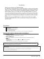 3
3
-
 4
4
-
 5
5
-
 6
6
-
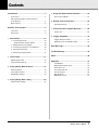 7
7
-
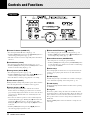 8
8
-
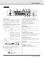 9
9
-
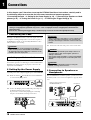 10
10
-
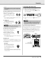 11
11
-
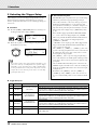 12
12
-
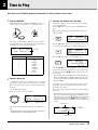 13
13
-
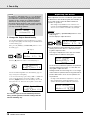 14
14
-
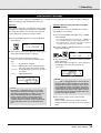 15
15
-
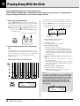 16
16
-
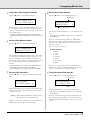 17
17
-
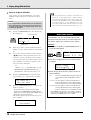 18
18
-
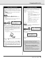 19
19
-
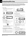 20
20
-
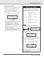 21
21
-
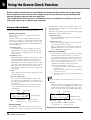 22
22
-
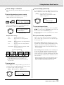 23
23
-
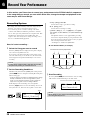 24
24
-
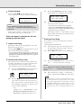 25
25
-
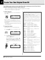 26
26
-
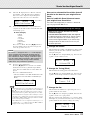 27
27
-
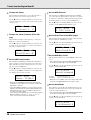 28
28
-
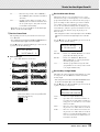 29
29
-
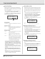 30
30
-
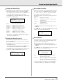 31
31
-
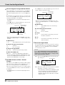 32
32
-
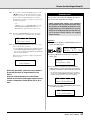 33
33
-
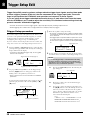 34
34
-
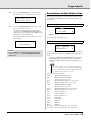 35
35
-
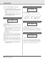 36
36
-
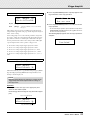 37
37
-
 38
38
-
 39
39
-
 40
40
-
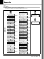 41
41
-
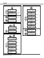 42
42
-
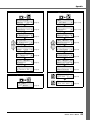 43
43
-
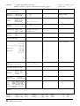 44
44
-
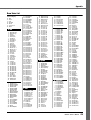 45
45
-
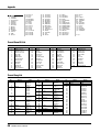 46
46
-
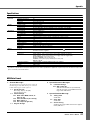 47
47
-
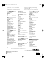 48
48


Yamaha DTX500 Le manuel du propriétaire
- Catégorie
- Batterie de musique
- Taper
- Le manuel du propriétaire
dans d''autres langues
- italiano: Yamaha DTX500 Manuale del proprietario
- English: Yamaha DTX500 Owner's manual
- español: Yamaha DTX500 El manual del propietario
- Deutsch: Yamaha DTX500 Bedienungsanleitung
- русский: Yamaha DTX500 Инструкция по применению
- Nederlands: Yamaha DTX500 de handleiding
- português: Yamaha DTX500 Manual do proprietário
- dansk: Yamaha DTX500 Brugervejledning
- polski: Yamaha DTX500 Instrukcja obsługi
- čeština: Yamaha DTX500 Návod k obsluze
- svenska: Yamaha DTX500 Bruksanvisning
- Türkçe: Yamaha DTX500 El kitabı
- română: Yamaha DTX500 Manualul proprietarului
Documents connexes
-
Yamaha DTX430K Le manuel du propriétaire
-
-
-
-
-
-
-
-
-