LG R1001E Le manuel du propriétaire
- Catégorie
- Climatiseurs split-system
- Taper
- Le manuel du propriétaire
Ce manuel convient également à

ROOM AIR CONDITIONER
OWNER'S MANUAL
MANUEL D'UTILISATION
CLIMATISEUR DE FENÊTRE
website http://www.LG.ca
Please read the operating instructions and safety precautions
carefully and thoroughly before installing and operating your
room air conditioner.
Veuillez lire attentivement et en entier ce guide d’utilisation et
le
s mesures de sécurité ci-incluses avant de procéder à
l’installation et au fonctionnement de votre climatiseur.
MODEL, MODÉLE
WL Series:

2 Room Air Conditioner
Window-Type Air Conditioner Owner’s Manual
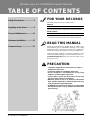
TABLE OF CONTENTS
FOR YOUR RECORDS
Write the model and serial numbers here:
Model #
Serial #
You can find them on a label on the side of each unit.
Dealer's Name
Date Purchased
■ Staple your receipt to this page in the event you need
it to prove date of purchase or for warranty issues.
READ THIS MANUAL
Inside you will find many helpful hints on how to use
and maintain your air conditioner properly. Just a little
preventive care on your part can save you a great deal
of time and money over the life of your air conditioner.
You'll find many answers to common problems in the
chart of troubleshooting tips. If you review our chart of
Troubleshooting Tips first, you may not need to call
for service at all.
PRECAUTION
• Contact the authorized service technician for repair or
maintenance of this unit.
• Contact the installer for installation of this unit.
• The air conditioner is not intended for use by young
children or invalids without supervision.
• Young children should be supervised to ensure that
they do not play with the air conditioner.
• When the power cord is to be replaced, replacement
work shall be performed by authorized personnel only
using only genuine replacement parts.
• Installation work must be performed in accordance with
the National Electric Code by qualified and authorized
personnel only.
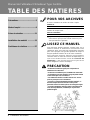
Safety Precautions.....................3
Operating Instructions ..............8
Care and Maintenance.............11
Hardware Installation ..............13
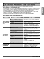
Common Issues.......................27

Owner's Manual 3
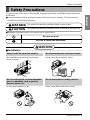
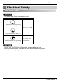
Safety Precautions
ENGLISH
To prevent injury to the user or other people and property damage, the following instructions must
be followed.
■ Incorrect operation due to ignoring instruction will cause harm or damage. The seriousness is
classified by the following indications.
WARNING
CAUTION
This symbol indicates the possibility of death or serious injury.
This symbol indicates the possibility of injury or damage to properties only.
■ Meanings of symbols used in this manual are as shown below.
Be sure not to do.
Be sure to follow the instruction.
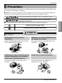
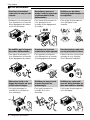
WARNING
■ Installation
Always install the expansion panel(s).
• No installation may cause fire and electric
shock accident.
Do not place the power cord near a heater.
• It may cause fire and electric shock.
Do not use the power cord near flammable
gas or combustibles such as gasoline,
benzene, thinner, etc.
• It may cause explosion or fire.
Do not disassemble or modify products.
• It may cause failure and electric shock.
Gasolin
Safety Precautions

4 Room Air Conditioner
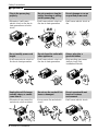
Safety Precautions
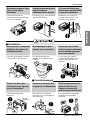
■ Operation
Plug in the power plug
properly.
• Otherwise, it will cause
electric shock or fire due to
heat generation or electric
shock.
Do not operate or stop the
unit by inserting or pulling
out the power plug.
• It will cause electric shock or
fire due to heat generation.
Do not damage or use an
unspecified power cord.
• It will cause electric shock or
fire.
Do not modify power cord
length.
• It will cause electric shock or
fire due to heat generation.
Do not share the outlet with
other appliances.
• It will cause electric shock or
fire due to heat generation.
Always plug into a
grounded outlet.
• No grounding may cause
electric shock (See
Installation Manual).
Unplug the unit if strange
sounds, odors, or smoke
come from it.
• Otherwise it may cause fire
and electric shock accident.
Do not use the socket if it is
loose or damaged.
• It may cause fire and electric
shock.
Do not operate with wet
hands or in damp
environment.
• It will cause electric shock.
ON

Owner's Manual 5
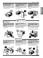
Safety Precautions
ENGLISH
Do not allow water to run
into electric parts.
• It will cause failure of machine
or electric shock.
Leave the door closed while
the air conditioner is
running.
• It is not designed to cool the
entire house.
Ventilate before operating
air conditioner when gas
goes out.
• It may cause explosion, fire,
and burn.
Never touch the metal parts
of the unit when removing
the filter.
• They are sharp and may
cause injury.
Do not block the inlet or
outlet.
• It may cause failure of
appliance or accident.
Ensure that the outer case
is not damaged by age or
wear.
• If leaving appliance damaged,
there is concern of damage
due to the falling of product.
Be cautious not to touch the
sharp edges when
installing.
• It may cause injury.
Hold the plug by the head
when taking it out.
• It may cause electric shock
and damage.
Turn off the main power
switch when not using it for
a long time.
• Prevent accidental startup
and the possibility of injury.
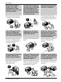
CAUTION
■ Installation
Sharp
edges
■ Operation

6 Room Air Conditioner
Safety Precautions
Do not place heavy object
on the power cord and take
care so that the cord should
not be pressed.
• There is danger of fire or
electric shock.
If water enters the product,
turn off the the power switch
of the main body of appliance.
Contact service center after
taking the power-plug out
from the socket.
Do not clean the air
conditioner with water.
• Water may enter the unit and
degrade the insulation. It may
cause an electric shock.
Turn off the power and
breaker firstly when
cleansing the unit.
• Since the fan rotates at high
speed during operation, it
may cause injury.
Do not put a pet or house
plant where it will be
exposed to direct air flow.
• This could injure the pet or
plant.
Do not use this appliance
for special purposes such
as pets, foods, precision
machinery, or objects of art.
• It is an air conditioner, not a
precision refrigeration system.
Always insert the filter
securely.
Clean it every two weeks.
• Operation without filters will
cause failure.
Use a soft cloth to clean. Do
not use wax, thinner, or a
strong detergent.
• The appearance of the air
conditioner may deteriorate,
change color, or develop
surface flaws.
Do not drink water drained
from air conditioner. / Do
not direct airflow at room
occupants only.
• It contains containments and
will make you sick. / This
could damage your health.
Wax
Thinner

Owner's Manual 7
Safety Precautions
ENGLISH
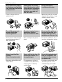
Preparing for operation
Contact an installation specialist for installation.
Plug in the power plug properly.
Do not share the same outlet with other appliances
Do not use an extension cord.
Do not start/stop operation by plugging/unplugging the power cord.
If cord/plug is damaged, replace only with an authorized part.
6
5
4
3
2
1
Usage
Cleaning and maintenance
Do not touch the metal parts of the unit when removing the filter. Injuries can occur when handling sharp
metal edges.
Do not use water to clean inside the air conditioner. Exposure to water can destroy the insulation, leading
to possible electric shock.
When cleaning the unit, first make sure that the power and breaker are turned off. The fan rotates at a
very high speed during operation. There is a possibility of injury if the unit’s power is accidentally
triggered on while cleaning inner parts of the unit.
3
2
1
Service
For repair and maintenance, contact your authorized service dealer.
Being exposed to direct airflow for an extended period of time could be hazardous to your health. Do not
expose occupants, pets, or plants to direct airflow for extended periods of time.
Due to the possibility of oxygen deficiency, ventilate the room when using together with stoves or other
heating devices.
Do not use this air conditioner for non-specified special purposes (e.g. preserving precision devices,
food, pets, plants, and art objects). Usage in such a manner could harm such property.
3
2
1
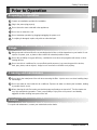
Prior to Operation

OPERATIONTHERMOSTAT
OFF
HIGH
COOL
MED
COOL
LOW COOL
MED
FAN
LOW
FAN
8 Room Air Conditioner
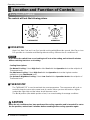
Operating Instructions
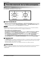
Location and Function of Controls
The controls will look like following picture.
■ OPERATION
High Cool, Med Cool and Low Cool provide cooling with different fan speeds. Med Fan or Low
Fan provides air circulation and filtering without cooling. Off turns the air conditioner off.
: If you move the switch from a cool setting to off or to a fan setting, wait at least 3 minutes
before switching back to a cool setting.
Cooling Descriptions
For Normal Cooling- Select High Cool or Med Cool with the Operation knob at the midpoint of
Thermostat knob.
For Maximum Cooling- Select High Cool with the Operation knob at the highest number
available on your Thermostat knob.
For Quieter & Nighttime Cooling- Select Low Cool with the Operation knob at the midpoint of
Thermostat knob.
■ THERMOSTAT
The THERMOSTAT is used to maintain the room temperature. The compressor will cycle on
and off to keep the room at the same level of comfort. When you turn the knob to a higher
number(the right side) and the indoor air will become cooler.
The 5 or 6 position (the middle position of arc) is a normal setting for average conditions.
CAUTION
: When the air conditioner has been performed its cooling operation and is turned off or set to
the fan position, wait at least 3 minutes before resetting to the cooling operation again.
NOTICE
Function of Controls

Owner's Manual 9
Operating Instructions
ENGLISH
Power
Te mp
Fan Speed
Timer Mode
˚C
TIMER POWERMODE
TEMP
FAN
SPEED
F1 LOW
F2 MED
F3 HIGH
Dry Timer
Fan
Energy
Saver
Cool
1
2
6
3 45
1
2
3
4
5
Push out the cover on the back of the remote control with your thumb
Pay attention to polarity and insert two new AAA 1.5V batteries.
Reattach the cover.
:
Do not use rechargeable batteries. Make sure that both batteries are new.
• In order to prevent discharge, remove the batteries from the remote control if the air
conditioner is not going to be used for an extended period of time
Keep the remote control away from extremely hot or humid places.
To maintain optimal operation of the remote control, the remote sensor should not be
exposed to direct sunlight.
• The remote control can be mounted on a wall using the mountable holder.
NOTICE
3
2
1
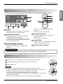
Inserting the Remote Control Batteries
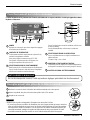
POWER
Operation starts when this button is pressed and
stops when you press the button again.
TEMPERATURE CONTROL
The thermostat monitors room temperature to
maintain the desired temperature.
The thermostat can be set between 16°C~30°C.
The unit takes an average of 30 minutes to adjust
the room temperature by 1°C.
OPERATION MODE SELECTOR
Select cooling mode to cool the room.
Select energy saver mode for energy saving
operation.
Select fan mode for basic ventilating fan
operation.
Select dry mode for dry operation.
FAN SPEED SELECTOR
For increased power while cooling, select a
higher fan speed.
3 steps: High ➔ Low ➔ Med
ON/OFF TIMER
The timer can be set to start and stop the unit in
hourly increments (up to 12 hours).
REMOTE CONTROL SENSOR
6
5
4
3
2
1
Remote Control OperationsRemote Control Operations
AUTO RESTART
In failure of electric power, the unit runs as previous setting operation.
The remote control and control panel will look like those represented in the following pictures.

10 Room Air Conditioner
Operating Instructions
VENTCLOSE
OPEN
Part
A
Vent Control
For maximum cooling efficiency, CLOSE the vent. This will allow internal air circulation.
OPENtheventtodischargestaleair.
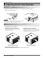
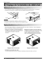
Adjusting the Air Flow Direction
• Recommended orientation of louvers
Adjust louvers to face upwards when cooling to maximize cooling efficiency.
Airflow can be adjusted by changing the direction of the air conditioner's louvers. This can also increase the
cooling efficiency of the air conditioner.
: Before using the ventilation feature, position the vent lever by
pulling Part A out straight and snapping it into place.
NOTICE
Adjusting horizontal air flow Adjusting vertical air flow
• Adjusting Horizontal Air Flow Direction
Adjusting the vertical louvers left and right will
change horizontal airflow.
• Adjusting Vertical Air Flow Direction
Adjusting the horizontal vane up and down will
change vertical airflow. The vane can be adjusted
by nudging the vane backward or forward.
Adjusting the Air Flow Direction

Owner's Manual 11
Care and Maintenance
ENGLISH
Drain pipe
Drain cap
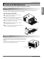
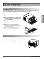
Turn the power off and unplug the power plug before cleaning the air conditioner.
Air Filter
The air filter behind the inlet grille should be checked and cleaned at least once every 2 weeks (or as
necessary) to maintain optimal performance of the air conditioner.
How to remove the air filter
The grille may be opened from the top for easy
maintenance after installation.
Open the inlet grille by pulling off the exposed door
on the top of the unit (based on installation).
Pull the tab slightly to release the filter. Pull the filter
in the same direction as the opening.
Clean the filter with warm, soapy water. The water
should be below 40°C (104°F).
Rinse off and gently shake off excess water from the
filter. Let it dry before replaceing it.
5
4
3
2
1
Drainage
The base pan may overflow due to high humidity. To drain the excess
water, remove the drain cap from the back of the unit and secure the
drainpipe.
When pressing the drainpipe into place, apply force in the direction
away from the fins to avoid injuring yourself.
Care and Maintenance

12 Room Air Conditioner
Care and Maintenance
CABINET
DRAIN
PAN
DRAIN HOSE
SCREW
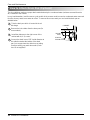
Take the drain pan which is located in the air
discharge.
Remove the hole rubber from the base-pan (for
some models).
Install the drain pan to the right corner of the
cabinet with 4 (or 2) screws.
Connect the drain hose of 3/5" inside diameter to
the outlet located at the bottom of the drain
pan.You can purchase the drain hose or tubing
locally to satisfy your particular needs. (Drain
hose is not supplied).
4
3
2
1
How to Attach Drain Pan (Optional)
The air conditioner employs a proper drain method whereby the condensed water (moisture removed from the
air) is drained to the outside.
In very humid weather, (and for reverse cycle models in the reverse mode) excessive condensate water removed
from the air may cause some water to collect. To remove this excess water you can install the drain pan as
detailed below.

Owner's Manual 13
Hardware Installation
ENGLISH
B
A
Power cord
Power cord
4
6
5
8
1
2
3
13
15
11
14
12
10
9
7
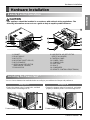
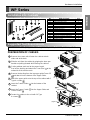
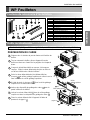
Product Features
1. CABINET
2. FRONT GRILLE
3. AIR FILTER
4. AIR INTAKE (INLET GRILLE)
5. AIR DISCHARGE
6. VERTICAL AIR DEFLECTOR
(HORIZONTAL LOUVER)
7. EVAPORATOR
8. HORIZONTAL AIR DEFLECTOR
(VERTICAL LOUVER)
9. CONTROL PANEL
10. POWER CORD
11. COMPRESSOR
12. BASE PAN
13. BRACE
14. CONDENSER
15. REMOTE CONTROLLER(OPTIONAL)
Remote Control Operations
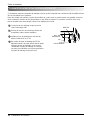
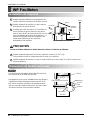
Installing the Power cord
You can choose between two methods below according to your window stool shape and preference.
• Fasten the stopper using 2 screw holes, and lead
out the power cord through slit "A".
• Fasten the stopper using left screw hole, and rotate
properly to lead the power cord out through slit "B".
Using slit "A" Using slit "B"
CAUTION
: This appliance should be installed in accordance with national wiring regulations. The
following information serves acts as a guide to help to explain product features.
Hardware Installation

14 Room Air Conditioner
Hardware Installation
About
1
/2"
30"~60"
Awning
Cooled air
Fence
Over 20"
Heat
radiation
23" to 36"
Offset
1
/2" to 1
1
/4"
Sill
Exterior
Interior wall
20
1
/12" min.
(Without frame curtain)
Stool
15" min
(With frame curtain)
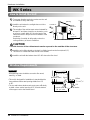
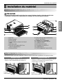
How to Install the Unit
To prevent vibration and noise, make sure the unit
is installed securely and firmly.
Install the unit where the sunlight does not shine
directly on the unit.
The outside of the cabinet must extend outward for
at least 12" and there should be no obstacles, such
as a fence or wall, within 20" from the back of the
cabinet because it will prevent heat radiation of the
condenser.
Restriction of outside air will greatly reduce the
cooling efficiency of the air conditioner.
CAUTION
: All side louvers of the cabinet must remain exposed to the outside of the structure.
Install the unit a little slanted so the back is slightly lower than the front (about 1/2").
This will force condensed water to flow to the outside.
Install the unit with the bottom about 30"~60" above the floor level.
5
4
3
2
1
Window Requirements
: All supporting parts should be secured to firm wood,
masonry, or metal.
• This unit is designed for installation in standard double
hung windows with actual opening widths from 23"
to 36".
• The top and bottom window sash must open sufficiently
to allow a clear vertical opening of 15" from the bottom
of the upper sash to the window stool.
NOTICE
WK Series

Owner's Manual 15
Hardware Installation
ENGLISH
About
1
/2"
30"~60"
Awning
Cooled air
Fence
Over 20"
Heat
radiation
27" to 39"
Offset
1
/2" to 1
1
/4"
Sill
Exterior
Interior wall
23
5
/8" min.
(Without frame curtain)
Stool
16" min
(With frame curtain)
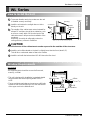
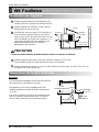
How to Install the Unit
To prevent vibration and noise, make sure the unit
is installed securely and firmly.
Install the unit where the sunlight does not shine
directly on the unit.
The outside of the cabinet must extend outward for
at least 12" and there should be no obstacles, such
as a fence or wall, within 20" from the back of the
cabinet because it will prevent heat radiation of the
condenser.
Restriction of outside air will greatly reduce the
cooling efficiency of the air conditioner.
CAUTION
: All side louvers of the cabinet must remain exposed to the outside of the structure.
Install the unit a little slanted so the back is slightly lower than the front (about 1/2").
This will force condensed water to flow to the outside.
Install the unit with the bottom about 30"~60" above the floor level.
5
4
3
2
1
Window Requirements
: All supporting parts should be secured to firm wood,
masonry, or metal.
• This unit is designed for installation in standard double
hung windows with actual opening widths from 27"
to 39".
• The top and bottom window sash must open sufficiently
to allow a clear vertical opening of 16" from the bottom
of the upper sash to the window stool.
NOTICE
WL Series

16 Room Air Conditioner
Hardware Installation
About
1
/2"
30"~60"
Awning
Cooled air
Fence
Over 20"
Heat
radiation
29" to 41"
18" min.
Inner sill
Offset
Window
Sash
Sill
Exterior
Interior wall
29" min.
(Without frame curtain)
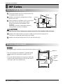
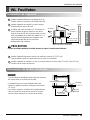
How to Install the Unit
To prevent vibration and noise, make sure the unit
is installed securely and firmly.
Install the unit where the sunlight does not shine
directly on the unit.
There should be no obstacles, such as a fence and
wall, within 20" from the back of the cabinet
because it will prevent heat radiation of the
condenser.
Restriction of outside air will greatly reduce the
cooling efficiency of the air conditioner.
CAUTION
: All side louvers of the cabinet must remain exposed to the outside of the structure.
Install the unit a little slanted so the back is slightly lower than the front (about 1/2").
This will force condensed water to flow to the outside.
Install the unit with the bottom about 30"~60" above the floor level.
5
4
3
2
1
Window Requirements
: All supporting parts should be secured to firm wood, masonry, or metal.
• This unit is designed for installation in standard double
hung windows with actual opening widths from 29"
to 41".
• The top and bottom window sash must open sufficiently
to allow a clear vertical opening of 18" from the bottom
of the upper sash to the window stool.
NOTICE
WP Series

Owner's Manual 17
Hardware Installation
ENGLISH
1
2 3 4
8 13
10
765
12
119
10
13
Shipping
Screws
(Type A)
(Type A)
5
11
11
5
5
Upper guide
Upper guide
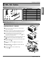
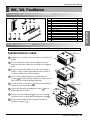
Installation Kits Contents
Suggested Tool Requirements
NO. NAME OF PARTS Q'TY
1 FRAME CURTAIN 2
2 SILL SUPPORT 2
3BOLT 2
4NUT 2
5 SCREW (TYPE A) 16
6 SCREW (TYPE B) 3
7 SCREW (TYPE C) 5
8FOAM-STRIP 1
9DRAINPIPE 1
10 FOAM-PE 1
11 FRAME GUIDE 2
12 WINDOW LOCKING BRACKET 1
13 FOAM-PE 1
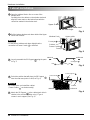
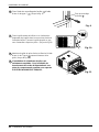
PREPARATION OF CHASSIS
Remove the screws which fasten the cabinet at both
sides and at the back.
Slide the unit from the cabinet by gripping the base pan
handle and pulling forward while bracing the cabinet.
Cut the window sash seal to the proper length.
Peel off the backing and attach the Foam-PE
to the
underside of the window sash.
Remove the backing from the top upper guide Foam-PE
and attach it to the bottom of the Upper Guide.
Attach the upper guide onto the top of the cabinet with 3
Type A screws
.
Insert the Frame Guides into the bottom of the
cabinet.
Insert the Frame Curtain
into the Upper Guide and
Frame Guides .
Fasten the curtains to the unit with 4 Type
A screws .
8
7
6
5
4
3
2
1
SCREWDRIVER(Philips and Flatead), RULER, KNIFE, HAMMER, PENCIL, LEVEL
WK, WL Series

18 Room Air Conditioner
Hardware Installation
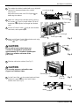
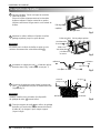
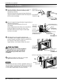
Cabinet Installation
Open the window. Mark a line on center of the
window stool.
Carefully place the cabinet on the window stool and
align the center mark on the bottom front with the
center line marked in the window stool.
Pull the bottom window sash down behind the Upper
Guide until it meets.
: Do not pull the window sash down tightly that the
movement of Frame Curtain
is restricted.
Loosely assemble the Sill Support using the parts
in Fig. 3.
Select the position that will place the Sill Support
near the outer most point on sill (See Fig. 4)
: Be careful when you install the cabinet
(Frame Guides are broken easily).
Attach the Sill Support to the cabinet track hole in
relation to the selected position using 2 Type A
screws in each support (See Fig. 4).
5
NOTICE
4
3
NOTICE
2
1
INDOOR OUTDOOR
Sill Support
2
Nut
4
Bolt
3
INDOOR OUTDOOR
Cabinet
About
1
/2"
Frame Guide
11
Screw(Type A)
5
Upper Guide
Window stool
Front Angle
Window Sash Upper guide
Frame Curtain
1
Foam-pe
10
Foam-pe
13
Cabinet
Fig. 1
Fig. 2
Fig. 3
Fig. 4

Owner's Manual 19
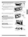
Hardware Installation
ENGLISH
Sash track
Front Angle
About
1
/2"
Screw(Type B)
6
Screw(Type B)
6
Sill Support
2
Sill Support
2
Foam-Strip
8
Fig. 5
Type C
7
Fig. 6
Screw(Type A)
Screw
(Type A)
Power cord
Fig. 7
Fig. 8
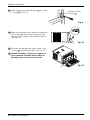
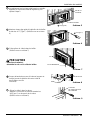
The cabinet should be installed with a very slight tilt
(about 1/2") downward toward the outside
(See Fig. 5).
Adjust the bolt and the nut of Sill Support for
balancing the cabinet.
Attach the cabinet to the window stool by driving
the screws
(Type B: Length 16mm (5/8 inch)
and below.) through the front angle into window
stool.
Pull each Frame Curtain
fully to each window
sash track, and repeat step 2.
Attach each Frame Curtain the window sash using
screws (Type C). (See Fig. 6)
CAUTION
:
Donotdrillaholeinthebottompan.
The unit is designed to operate with
approximately 1/2" of water in bottom pan.
There is no need to add water if the
panisdry.
Slide the unit into the cabinet. (See Fig. 7)
CAUTION
:
For security purpose, reinstall screws
(Type A) at cabinet's sides.
Cut the Foam-Strip to the proper length and insert
between the upper window sash and the lower
window sash. (See Fig. 8)
11
10
9
8
7
6

20 Room Air Conditioner
Hardware Installation
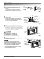
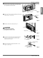
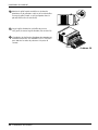
Attach the Window Locking Bracket withaType
C screw .(SeeFig.9)
Attach the front grille to the cabinet by inserting the
tabsonthegrilleintothetabsonthefrontofthe
cabinet. Push the grille in until it snaps into place.
(See Fig. 10)
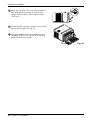
Pull down the inlet grille and secure it with a Type
A screw
through the front grille. (See Fig. 11)
Window installation of room air conditioner is
now completed. See ELECTRICAL DATA for
attaching power cord to electrical outlet.
15
14
13
12
Window locking
bracket
12
Fig. 9
Fig. 10
Fig. 11
La page est en cours de chargement...
La page est en cours de chargement...
La page est en cours de chargement...
La page est en cours de chargement...
La page est en cours de chargement...
La page est en cours de chargement...
La page est en cours de chargement...
La page est en cours de chargement...
La page est en cours de chargement...
La page est en cours de chargement...
La page est en cours de chargement...
La page est en cours de chargement...
La page est en cours de chargement...
La page est en cours de chargement...
La page est en cours de chargement...
La page est en cours de chargement...
La page est en cours de chargement...
La page est en cours de chargement...
La page est en cours de chargement...
La page est en cours de chargement...
La page est en cours de chargement...
La page est en cours de chargement...
La page est en cours de chargement...
La page est en cours de chargement...
La page est en cours de chargement...
La page est en cours de chargement...
La page est en cours de chargement...
La page est en cours de chargement...
La page est en cours de chargement...
La page est en cours de chargement...
La page est en cours de chargement...
La page est en cours de chargement...
La page est en cours de chargement...
La page est en cours de chargement...
La page est en cours de chargement...
La page est en cours de chargement...
-
 1
1
-
 2
2
-
 3
3
-
 4
4
-
 5
5
-
 6
6
-
 7
7
-
 8
8
-
 9
9
-
 10
10
-
 11
11
-
 12
12
-
 13
13
-
 14
14
-
 15
15
-
 16
16
-
 17
17
-
 18
18
-
 19
19
-
 20
20
-
 21
21
-
 22
22
-
 23
23
-
 24
24
-
 25
25
-
 26
26
-
 27
27
-
 28
28
-
 29
29
-
 30
30
-
 31
31
-
 32
32
-
 33
33
-
 34
34
-
 35
35
-
 36
36
-
 37
37
-
 38
38
-
 39
39
-
 40
40
-
 41
41
-
 42
42
-
 43
43
-
 44
44
-
 45
45
-
 46
46
-
 47
47
-
 48
48
-
 49
49
-
 50
50
-
 51
51
-
 52
52
-
 53
53
-
 54
54
-
 55
55
-
 56
56


LG R1001E Le manuel du propriétaire
- Catégorie
- Climatiseurs split-system
- Taper
- Le manuel du propriétaire
- Ce manuel convient également à
dans d''autres langues
- English: LG R1001E Owner's manual
Documents connexes
-
LG TWC121LLMK0 Le manuel du propriétaire
-
LG LW081CS Le manuel du propriétaire
-
-
-
-
-
-
-
-