Honeywell Home DR90A3000/U Guide d'installation
- Taper
- Guide d'installation

33-00297EFS-15
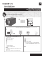
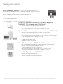
INCLUDED IN THIS BOX
OPTIONAL CONTROLS SOLD SEPARATELY
D2D4
D
Tools required to install DR65A3000 dehumidifier
3/8” hex drive
Drill or duct cutting tool
Wire stripper/cutter
Standard screwdriver
T20 Torx screwdriver
Duct tape
8” round duct and starter collar
1822 gauge, 5 conductor thermostat wire
1/2” diameter drain line (8’)
1/2” drain clamps (2)
3/4” male NPT drain outlet
Options
1/2” drain p-trap (may be required by local code)
Drain pan
Float switch or water sensor (normally closed)
C
A
B
D1
D2
D3
D4
DR65A3000 (1)
MERV 11 Filter (1)
Installation Guide
Prestige IAQ Kit
VisionPRO™ Smart or VisionPRO RedLINK®
H6062 HumidiPRO Digital Humidity Control
(HVAC fan wired to DR65, not H6062)
T10 or T10+ Pro Smart Thermostat
DR65A3000
PROFESSIONAL INSTALLATION GUIDE
GUIDE D’INSTALLATION PROFESSIONNELLE
GUÍA DE INSTALACIÓN PROFESIONAL
A B C
D1D3
INCLUDED IN THIS BOX
OPTIONAL CONTROLS SOLD SEPARATELY
D2D4
D
Tools required to install DR65A3000 dehumidifier
3/8” hex drive
Drill or duct cutting tool
Wire stripper/cutter
Standard screwdriver
T20 Torx screwdriver
Duct tape
8” round duct and starter collar
1822 gauge, 5 conductor thermostat wire
1/2” diameter drain line (8’)
1/2” drain clamps (2)
3/4” male NPT drain outlet
Options
1/2” drain p-trap (may be required by local code)
Drain pan
Float switch or water sensor (normally closed)
C
A
B
D1
D2
D3
D4
DR65A3000 (1)
MERV 11 Filter (1)
Installation Guide
Prestige IAQ Kit
VisionPRO™ Smart or VisionPRO RedLINK®
H6062 HumidiPRO Digital Humidity Control
(HVAC fan wired to DR65, not H6062)
T10 or T10+ Pro Smart Thermostat
DR65A3000
PROFESSIONAL INSTALLATION GUIDE
GUIDE D’INSTALLATION PROFESSIONNELLE
GUÍA DE INSTALACIÓN PROFESIONA L
A B C
D1D3
INCLUDED IN THIS BOX
OPTIONAL CONTROLS SOLD SEPARATELY
D2D4
D5
D
Tools required to install DR65A3000 dehumidifier
3/8” hex drive
Drill or duct cutting tool
Wire stripper/cutter
Standard screwdriver
T20 Torx screwdriver
Duct tape
8” round duct and starter collar
1/2” diameter drain line (8’)
1/2” drain clamps (2)
3/4” male NPT drain outlet
Options
1/2” drain p-trap (may be required by local code)
Drain pan
Float switch or water sensor (normally closed)
C
A
B
D1
D2
D3
D4
DR65A3000 (1)
MERV 11 Filter (1)
Installation Guide
Prestige IAQ Kit
H8908 Manual Dehumidistat
VisionPRO™ Smart or VisionPRO RedLINK®
H6062 HumidiPRO Digital Humidity Control
(HVAC fan wired to DR65, not H6062)
T10 Pro Smart
DR65A3000
PROFESSIONAL INSTALLATION GUIDE
GUIDE D’INSTALLATION PROFESSIONNELLE
GUÍA DE INSTALACIÓN PROFESIONAL
A B C
D1D3
INCLUDED IN THIS BOX
OPTIONAL CONTROLS SOLD SEPARATELY
D1D3
D2D4D5
D5
D
Tools required to install DR65A3000 dehumidifier
3/8” hex drive
Drill or duct cutting tool
Wire stripper/cutter
Standard screwdriver
T20 Torx screwdriver
Duct tape
8” round duct and starter collar
1/2” diameter drain line (8’)
1/2” drain clamps (2)
3/4” male NPT drain outlet
Options
1/2” drain p-trap (may be required by local code)
Drain pan
Float switch or water sensor (normally closed)
C
A
B
D1
D2
D3
D4
DR65A3000 (1)
MERV 11 Filter (1)
Installation Guide
Prestige IAQ Kit
TruelAQ
H8908 Manual Dehumidistat
VisionPRO™ Smart or VisionPRO™ RedLINK
H6062 HumidiPRO Digital Humidity Control
T10 Pro Smart
DR65A3000
PROFESSIONAL INSTALLATION GUID
E
GUIDE D’INSTALLATION PROFESSIONNELL
E
GUÍA DE INSTALACIÓN PROFESIONA
L
A B C
33-00297EFS-05
D6
D6
D5
33-00297EFS-11
Note: If IAQ thermostat such as Prestige™ IAQ kit is used, a separate dehumidity control is not needed.
Note: If IAQ thermostat such as Prestige™ IAQ kit is used, a separate dehumidity control is not needed.
33-00297EFS-13
Note: If IAQ thermostat such as Prestige™ IAQ kit is used, a separate dehumidity control is not needed.

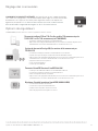
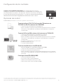
Installation Checklist
Included in This Box
A DR65A3000 (1)
B MERV 11 Filter (1)
C Installation Guide
Control Options (Sold separately)
D1 Prestige IAQ Kit
D2 VisionPRO Smart
or VisionPRO RedLINK
D3 H6062 digital control
D4 T10 or T10+ Pro Smart Thermostat
Tools Required (Not Supplied)
• 3/8” hex drive
• Drill or duct cutting tool
• Wire stripper/cutter
• Standard screwdriver
• T20 Torx screwdriver
• Duct tape
• 8” round duct and starter
collar
• 1822 gauge, 5 conductor thermostat
wire
• 1/2” diameter drain line (8’)
• 1/2” drain clamps (2)
• 3/4” male NPT drain outlet
Options
• 1/2” drain p-trap (may be required by
local code)
• Drain pan
• Float switch or water sensor (normally
closed)
Note: Float switch or drain pan required if
installed in location where water damage
can occur if drain line gets clogged.
Liste de vérification pour
l’installation
Inclus dans cette boîte
A DR65A3000 (1)
B Filtre MERV 11 (1)
C Guide d’installation
Options de régulateurs (vendus
séparément)
D1 Nécessaire Prestige IAQ
D2 VisionPRO Smart
ou VisionPRO RedLINK
D3 Commande numérique H6062
D4 Thermostat intelligent T10 ou T10+ Pro
Outils requis (non fournis)
• Tournevis cruciforme 3/8 po
• Outil de perçage ou de coupe de conduit
• Dénudeur/coupe-fils
• Tournevis normal
• Tournevis Torx T20
• Ruban adhésif
• Collet de conduit et de départ rond de 8
po
• Fil de thermostat à 5 conducteurs calibre
1822
• Tuyau de vidange de 1/2 po de dia. (8 pi)
• Attaches de tuyau de vidange de 1/2 po
(2)
• Sortie de vidange ¾ po NPT mâle
Options
• SiphonP de vidange d’1/2 po (peut-être
requis par le code local)
• Bac de récupération
• Flotteur ou capteur d’eau (normalement
fermé)
Remarque : Si l’appareil est installé dans
un endroit où des dégâts d’eau peuvent
se produire en cas d’obstruction de la
conduite de vidange, un interrupteur
à flotteur ou un bac de vidange est
nécessaire.
Lista de verificación para la
instalación
Esta caja incluye
A DR65A3000 (1)
B Filtro MERV 11 (1)
C Guía de instalación
Opciones de control (se venden por
separado)
D1 Kit Prestige IAQ
D2 VisionPRO Smart
o VisionPRO RedLINK
D3 Control digital de H6062
D4 Termostato inteligente T10 o T10+ Pro
Herramientas necesarias (no se suministran)
• Dado Exagonal de 3/8” (9.5mm)
• Taladro o herramienta cortante para ductos
• Alicates o cortadores de cables
• Destornillador estándar
• Destornillador Torx T20
• Cinta para Ductos
• Ducto redondo de 8” (20.3 cms) y collar de
ajuste
• Cable de termostato calibre 18 a 22, de 5
conductores
• Línea de desagüe de 1/2 pulgada
(12,7 mm) de diámetro (8 pies [2,4 m])
• Abrazaderas de desagüe de 1/2 pulgada
(12,7 mm) (2)
• Tubo de desagüe NPT macho de 3/4 pulgada
(19,1 mm)
Opciones
• Trampa en P para desagüe de ½ pulgada (12,7
mm) (es posible que el código local la exija)
• Bandeja para drenaje
• Interruptor del flotador o sensor de agua
(normalmente cerrado)
Nota: Se requiere un interruptor de flotador
o una bandeja de drenaje en caso de que
se instale en un lugar en el que el agua
pueda causar daños si la línea de drenaje se
obstruye.
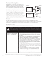
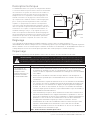
Warning: Installation must be
performed by a qualified service
technician and must comply with
local codes.
Remove power to the device before
installing or servicing the device.
Failure to connect the device
according to these instructions may
result in damage to the device or
the controls.
INSTALLATION INSTRUCTIONS
BEGIN ON PAGE 2
Avertissement : L’installation doit
être effectuée par un technicien
d’entretien qualifié et conformément
aux codes en vigueur.
Couper l’alimentation vers l’appareil
avant d’installer ou de réparer cet
appareil.
Un raccordement de cet appareil
non conforme à ces instructions
peut entraîner des dommages à
l’appareil ou aux commandes.
INSTRUCTIONS D’INSTALLATION
COMMENCER À LA PAGE 18
Advertencia: La instalación la debe
realizar un técnico de reparación
calificado y debe cumplir con los códigos
locales.
Retire la fuente de energía del dispositivo
antes de instalar o reparar el dispositivo.
Si no conecta el dispositivo según
estas instrucciones, el dispositivo o los
controles se pueden dañar.
LAS INSTRUCCIONES DE INSTALACIÓN
COMIENZAN EN LA PÁGINA 34

DR65A3000 - Read before installing
NEED HELP? For assistance with this product please visit
http://www.customer.resideo.com or call Customer Care toll-free at
18004681502.
?
DR65A3000 Dehumidification System 3300297EFS15
ABOUT YOUR NEW DEHUMIDIFIER
Benefits ....................................... 2
Maintaining Ideal Humidity ....................2
Setting the Controls ............................3
Control Options ................................3
Specifications .................................. 4
INSTALLATION
Install to Fit Your Application ................... 5
Plumbing ......................................6
Terminal Description ...........................7
Wiring .......................................7
Checkout .....................................10
MAINTENANCE
Cleaning ......................................11
Technical Description .........................12
Parts List ......................................14
5Year Limited Warranty ......................15
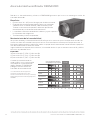
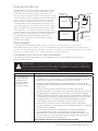
• The DR65A3000 is designed to be installed indoors in a space that is protected from rain and flooding.
• Install the unit with space to access the front panel for maintenance and service.
• Avoid directing the discharge air at people, or over the water in pool areas.
• If used near a pool or spa, be certain there is no chance the unit could fall into the water or be splashed,
and that it is plugged into a ground fault interrupt (GFI) outlet.
• To ensure quiet operation, do not place the device directly on the structural supports of the home.
• A drain pan must be placed under the unit if installed above a living area or above an area where
water leakage could cause damage.
• DR65 should be installed on a stationary base or sitting on the floor. It should not be mounted
above other HVAC components such as the A-coil.
1. Never operate a unit with a damaged power cord. If the power cord is damaged it must be
replaced by the manufacturer, its service agent, or similarly qualified person in order to
avoid a hazard.
2. The appliance is not intended for use by persons (including children) with reduced
physical, sensory, or mental capabilities, or lack of experience and knowledge, unless they
have been given supervision or instruction concerning use of the appliance by a person
responsible for their safety. Children should be supervised to ensure that they do not play
with the appliance.
!!

About the DR65A3000 Dehumidifier
The DR65A3000 ensures the home is maintained at proper humidity levels through its high performance and
efficiency.
Benefits
• Removes up to 65 pints (30.8 l) of water per day from the indoor
air.
• Built-in humidity control requires no additional wiring to an
external control. Just plug in and go! Choice of external control
options also available for centrally ducted control.
• Electrocoating reduces coil corrosion and helps prevent
refrigerant leaks
• Built-in transformer and fuse.
Maintaining Ideal Humidity
Dew points and relative humidity (RH) affect the way your body senses heat. Higher humidity levels cause
the air to feel much hotter than the actual temperature. When maintained properly, you can run your cooling
equipment less because dehumidified air feels cooler.
Ideal humidity is defined by industry experts* as being between 4060% on an average annual basis.
Capacity:
34 pints/day (60 ºF [15.6 ºC], 60 %RH)
47 pints/day (70 ºF [21.1 ºC], 60 %RH)
65 pints/day (80 ºF [26.7 ºC], 60 %RH)
When indoor humidity exceeds 60%,
the home is more susceptible to mold
and mildew growth. DR65A3000 safe-
guards against excessive humidity in
the home year-round.
*American Society of Heating, Refrigerating
and Air Conditioning Engineers (ASHRAE).
MCR24780
010203040506070809
01
00
OPTIMUM
ZONE
BACTERIA
VIRUSES
FUNGI
MITES
RESPIRATORY
INFECTIONS
ALLERGIC RHINITIS
AND ASTHMA
CHEMICAL
INTERACTIONS
OZONE
PRODUCTION
ASHRAE RECOMMENDED WINTER DESIGN LEVEL
DR65A3000 Dehumidification System 33-00297EFS—15
2

Setting the Controls
BUILTIN HUMIDITY CONTROL: An intuitive ‘set and forget’ humidistat is
built into the DR65A3000 to set the humidity level right on the device. Optional
external control wiring is also available. If an external dehumidistat is used, the
on-board dehumidification control should be set to 80% RH.
Control Options
The DR65A3000 may be used with one of the following external controls:
HumidiPRO Digital Control (H6062A1000)
• Manual dehumidification control
• Dehumidifier compressor protection
• RH% and outdoor temperature calibration
• Adjustable high and low range stops (1090%)
Prestige IAQ Thermostat Kit (kit numbers start with YTHX9421R)
• Controls heating/cooling, dehumidification, and ventilation.
• Wireless sensor for displaying outdoor temperature and humidity.
• Advanced dehumidifier setting options to run system fan with dehumidifier
or lock out dehumidifier if cooling is running.
• Maintenance and service reminders.
• High definition color display.
• RedLINK Wireless technology
VisionPRO Smart or VisionPRO RedLINK Thermostat
• WiFi (TH8321WF1001) or RedLINK Wireless technology (TH8321R1001)
• Controls heating/cooling and dehumidification.
• Display outdoor temperature and humidity.
• Advanced dehumidifier setting options to run system fan with
dehumidifier or lock out dehumidifier if cooling is running.
T10 or T10+ Pro Smart Thermostat (T10 models begin with
THX321WF. T10+ kits begin with YTHM1004R)
• Controls heating/cooling and dehumidification.
• Advanced dehumidifier setting options to run system fan with
dehumidifier or lock out dehumidifier if cooling is running.
DR65A3000 Dehumidification System 33-00297EFS—15 3

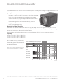
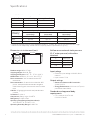
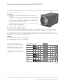
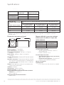
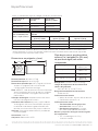
Specifications
Install DR65A3000 according to National Electric Codes.
Dimensions in inches and (mm):
Product weight: 60lb (27 Kg)
Shipping weight: 68lb (31 Kg)
Shipping dimensions: 16.7” H × 17” W × 32.9” L
Media Filter: MERV 11, 9” H x 11” W x 0.75” D
Drain connection: 3/4” threaded female NPT
connection.
Duct connections: 8” round inlet and outlet. ABS
plastic, compatible for connection to rigid or
flexible ducting with sheet metal screws and/or
tape.
Cabinet: 20 gauge galvanized steel powder-coat
painted.
Insulation: R value 1
Compressor: Rotary-style, 6.1 KBTU
Refrigerant: R410A, 15 oz.
Operating Temp Range (outside cabinet):
34ºF to 135ºF (1.1ºC to 57.2ºC)
Operating Humidity Range: 099% RH
Input ratings
• Electrical input voltage: 120 VAC, 60 Hz
nominal
• Input current: 5.2 A
Output ratings
• Power transformer to R/C terminals:
24 VAC, 0.85 A
• Energy Performance: 2.22 liters (4.7 pints)
per kilowatt hour (KWH)
Standards and approval body
requirements
• ETL Listed per UL 474 and
CSA C22.2 No 92
DryBulb Temp Intake Humidity Capacity (Pints/Day)
80°F (26.7°C) 60% RH 65
70°F (21.1°C) 60% RH 47
60°F (15.6°C) 60% RH 34
Home Size
(square ft) @
8 ft ceiling
Dehumidifier Capacity Required to Maintain Desired Indoor RH*
60% RH Indoor
(pints/day) 50% RH Indoor
(pints/day) 40% RH Indoor
(pints/day)
2080 4954 5558 7178
2600 6168 6572 9097
3120 7582 7986 95110
* Based on extreme climates where outdoor humidity is 7090% RH. For less extreme climates, larger
homes can be adequately served with less capacity. Actual requirements may vary.
Airflow versus external static pressure
(01” water pressure) with collars
attached
0” 160 CFM
0.2” 140 CFM
0.4” 120 CFM
0.6” 100 CFM
M29763
28-1/2 (724)
12 (305)
12
(305)
8 INCH (203)
DIAMETER
DR65A3000 Dehumidification System 33-00297EFS—15
4

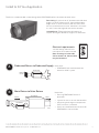
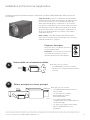
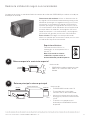
Install to Fit Your Application
Ideal when…
• DR65A3000 will not be ducted to a
forced air HVAC system.
DEHUMIDIFIER
M36846
SEPARATE
RETURN
SUPPLY
Dedicated Return to Dedicated Supply
A
DR65A3000 Dehumidification System 33-00297EFS—15 5
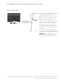
Flex duct is recommended in connecting to the DR65A3000 collars to reduce vibration noise.
M24745
Electrical requirements:
120 VAC outlet. Ground fault
interrupter (GFI) recommended.
Note: If voltage is below 102
VAC or above 132, dehumidifier
may be locked out.
Duct Sizing: Use minimum 8” diameter round for duct
lengths up to 25’ Minimum 10” required for lengths
longer than 25’ Duct branches from the main inlet/
exhaust should be minimum 8” round for 23 branch-
es, and 8” round or larger for 4 branches or more.
Isolated Areas: Effective dehumidification may
require ducting to isolated or stagnant air flow areas.
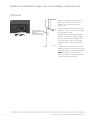
BMain Return to Main Return Ideal when…
• Running DR65A3000 with A/C
operation.
• System fan must run with dehumidifier.
• Minimizing discharge air temperature
(DAT) increase is preferred.
• Access to a dedicated central return for
DR65A3000 is not available.
SUPPLY
RETURN
AIR HANDLER
M36845
DEHUMIDIFIER

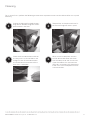
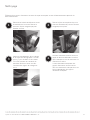
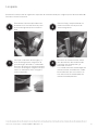
Attach 3/4" male NPT PCV drain noz-
zle (use teflon tape if needed). Do not
over-tighten.
Connect 1/2” drain tube to male con-
nection drain outlet.
Secure drain tube to connector with
hose clamp.
Run drain hose continuously downhill
to an approved drain or condensate
pump.
The drain line must include a water
trap to prevent air from entering or
exiting the dehumidifier.
NOTE: It is important that the DR65 is
leveled for drain line to work properly.
Plumbing
Install to Fit Your Application (continued)
IMPORTANT: LOOP
DRAIN HOSE BELOW
DEHUMIDIFIER
TO PROVIDE TRAP
M38989
DR65A3000 Dehumidification System 33-00297EFS—15
6

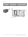
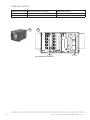
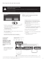
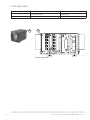
Terminal Description
NOTE: The outer screws on each
terminal block secure the block to the
chassis. They are not used for wiring.
The six terminals for the left hand terminal block are:
FLOAT (2): External low-voltage water sensor or float
switch
DHUM: Compressor and fan operation for
dehumidification
R: 24V hot (output)
FAN: Fan activation only for ventilation
C: 24V common (output)
External 24V devices can be powered from R and C
terminals (20VA max.)
The right hand terminal block in the above
image is used only for interlocking a
DR65A3000 with an equipment fan. These
terminals are needed if:
A: The dehumidifier is mounted on the HVAC
ducting.
B: The dehumidifier control cannot turn on the
blower fan with a call for dehumidification
(H6062, H8908).
The three terminals are:
Gt: Wires to G at thermostat
Rf: Wire to R at HVAC (furnace/air-handler)
Gf: Wire to G at HVAC (furnace/air-handler)
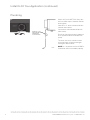
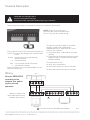
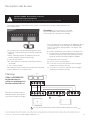
Wiring
Wire the DR65A3000
according to the
diagram that applies
to your desired
operation.
Follow this diagram for
ducted operation with the
onboard dehumidistat.
Two wiring terminal blocks are located on the exhaust end of the dehumidifier.
DEHUMIDIFIER
HVAC
THERMOSTAT
GYWRRc
GYWR C
M36847A
Gt
+
+
Rf Gf
DHUM
+
+
RFANC
FLOAT FLOAT
1
IF A FLOAT SWITCH IS NOT USED, THEN JUMPER THE FLOAT TERMINALS.
1
DR65A3000 Dehumidification System 33-00297EFS—15 7
CAUTION: Low voltage hazard.
Can cause equipment damage.
Disconnect HVAC equipment before beginning installation.

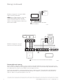
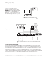
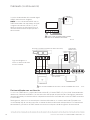
Wiring (continued)
Follow this diagram if using an
external manual dehumidistat.
DEHUMIDIFIER
HVAC
THERMOSTAT
GYWRRc
GYWR C
M36848
B
DRY
CONTACTS
Gt
+
+
Rf Gf
DHUM
+
+
RFANC
FLOATFLOAT
IF A FLOAT SWITCH IS NOT USED, THEN JUMPER THE FLOAT TERMINALS.
1
1
H8908 MECHANICAL
DEHUMIDISTAT
Dehumidifier with zoning
When a DR65 is used with a zoned system, wire Rf and Gf from DR65 to R and G at HVAC (furnace/air-han-
dler). Wire Gt from DR65 to G on equipment terminals of zone panel. Set the dehumidity control to dehumid-
ify independent of system fan (the DR65 will be turning on the fan).
Usually only one control is used for the dehumidifier in a zoned system. That could be an IAQ thermostat
from a central zone or a stand alone dehumidity control. This control is wired to the R and DHUM on the
DR65 as shown in any of the diagrams in this file.
DR65A3000 Dehumidification System 33-00297EFS—15
8
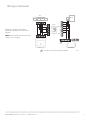
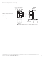
Follow this diagram if using the H6062
Digital Humidity Controller.
NOTE: When H6062 control is used with
a DR65 connected to HVAC ducting,
make sure to wire the Rf, GT, and GF as
shown in the diagram for the mechanical
dehumidistat below.
M37492A
C
R
U
U
S
S
24 VAC
(CONSTANT)
RFLOAT
DHUM
FANC
IF A FLOAT SWITCH IS NOT USED, THEN JUMPER
T
HE FLOAT TERMINALS.
1
1

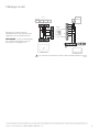
Wiring (continued)
Follow this diagram for ducted
operation with external ventilation
control.
NOTE: Dehumidity control circuit not
shown in this diagram.
DEHUMIDIFIER
HVAC
THERMOSTAT
GY
W
RRc
GYWR C
M36849A
EARD8TZ
R
C
DAMPER
AUX
REMOTE
W8150A
G
R
C
C
W
G
+
+
Gf
DHUM
+
+
FANC
FLOAT
IF A FLOAT SWITCH IS NOT USED, THEN JUMPER THE FLOAT TERMINALS.
1
1
Gt Rf
DR65A3000 Dehumidification System 33-00297EFS—15 9

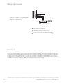
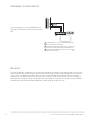
Wiring (continued)
Plug in the DR65A to power. Turn the humidity control knob to a low RH% level to initiate a dehumidification
call. Confirm that the DR65A3000 compressor and fan turn on. If the RF and GF on the DR65A is wired to the
furnace, the furnace fan should also run. There may be a delay of up to 5 minutes before the unit turns on.
When checkout is complete, be sure to turn the control to the desired RH%. If an external control is wired to
the DR65A, then turn the control knob on the DR65A to the highest RH setting.
Checkout
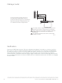
U3
U3
U2
U2
U1
U1
DEHUMIDIFIER
Gt
+
+
Rf Gf
DHUM
+
+
RFANC
FLOAT
IN THIS DIAGRAM, U1 CONTROLS THE DR65A FOR DEHUM AND U2
CONTROLS THE DR65A FOR VENTILATION.
INSTALL A JUMPER ON EIM AS SHOWN ONLY
WHEN USING THE DR65
FOR VENTILATION IN ADDITION TO DEHUMIDIFICATION.
IF A FLOAT SWITCH IS NOT USED, THEN JUMPER THE FLOAT TERMINALS.
1
2
12
3
3
EIM
M38419
DR65A3000 Dehumidification System 33-00297EFS—15
10
Follow this diagram if using DR65A3000
with either a Prestige or TH8321R1001
RedLINK VisionPro & EIM.

Cleaning
On an annual basis, perform the following maintenance requirement to ensure the dehumidifier runs at peak
efficiency.
DR65A3000 Dehumidification System 33-00297EFS—15 11
Unplug the dehumidifier before begin-
ning service. Remove magnetic access
panel to access the filter.
Remove filter and replace with new fil-
ter. Reinstall magnetic access panel.
When service is complete, initiate a
call for dehumidification and check
that the compressor and fan activate.
If your thermostat has maintenance
reminders, reset those. All thermostats
listed in this file have optional mainte-
nance reminders.
Check the drain connection and drain
line to ensure it is clear of debris and
sludge. Ensure all hose connections
are secure once maintenance of the
drain lines is complete.
1 2
3 4

Technical Description
DR65A3000 uses a refrigeration system similar to an air
conditioner to remove heat and moisture from incoming
air and add heat to the air that is discharged. Hot, high-
pressure refrigerant gas is routed from the compressor to
the condenser coil. The refrigerant is cooled and condensed
by giving up its heat to the air that is about to be discharged
from the unit. The refrigerant liquid then passes through a
filter drier and capillary tubing which causes the refrigerant
pressure and temperature to drop. It next enters the
evaporator coil where it absorbs heat from the incoming
air and evaporates. The evaporator operates in a flooded
condition, which means that all the evaporator tubes
contain liquid refrigerant during normal operation. A flooded
evaporator should maintain nearly constant pressure and
temperature across the entire coil, from inlet to outlet.
Troubleshooting videos are available on the Resideo Pro YouTube channel playlist.
CONDENSER
EVAPORATOR
CAPILLARY
TUBES
ACCUMULATOR
COMPRESSOR
STRAINER/FILTER
DRIER
M27404
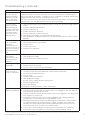
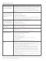
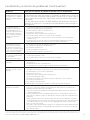
Problem Troubleshooting Steps/Possible Causes of Issue
Neither the dehumidifier fan nor
compressor run when the control
is calling for dehumidification.
1. Bypass any external control (if used) by turning the control
knob on DR65 to “ON”. If that works, and an external control is
used, troubleshoot the control and wiring to the R and DHUM
on DR65.
2. Verify the drain line is not clogged. An internal float switch can
lock out the dehumidifier if the drain line gets clogged.
3. Wait 5 minutes from the time you made the call for dehumidity.
Series 2 versions of the DR65 have a 25 minute compressor
protection delay. If the control is digital, it may also have a
delay. These delays will overlap, so if the humidity control has
been calling for over 5 minutes and power has not cycled, the
dehumidifier should run.
4. If it does not run after the delay, install a jumper between the
R and DHUM terminals on the dehumidifier. This bypasses the
control circuit. If the unit runs, the issue was with the control or
wires to the control.
5. If the unit still does not run within 5 minutes of installing a
jumper from R to DEHUM, verify voltage to the outlet that
the dehumidifier is plugged into. This should be 120 VAC
nominal and if it drops below 102 VAC or above 132 VAC, the
dehumidifier will not run.
Note: Be sure to remove the jumper after testing.
Troubleshooting
CAUTION: Servicing the DR65A3000 with its high pressure refrigerant system and high
voltage circuitry presents a health hazard which could result in death, serious bodily injury,
and/or property damage. Service should only be performed by a qualified service technician.
Defrost
If the DR65 dehumidifier coil starts to freeze up it goes into defrost mode. The dehumidifier shuts off the
compressor and runs the fan until the coil temperature rises. For rev 2 models (a sideways 2 after the model number
on the sticker) the dehumidifier makes a single beep when first powered up or when it enters defrost mode.
DR65A3000 Dehumidification System 33-00297EFS—15
12

Troubleshooting (continued)
Problem Troubleshooting Steps/Possible Causes of Issue
The dehumidifier
fan runs but the
compressor does
not when the con-
trol is calling for
dehumidification.
If there is a wire to “FAN” on the dehumidifier, remove that wire and see if the dehu-
midifier fan continues to run. If the fan shuts off, then whatever is controlling the
fan was calling for ventilation. That doesn’t mean a control is calling for dehumidity.
Follow the steps from the first issue for further testing.
If there is no wire to the “FAN” terminal and the dehumidifier FAN is running but the
compressor is not, the dehumidifier may be running in defrost.
Fan runs when
there is a call for
dehumidification
and the ventilation
control is OFF, but
the compressor
cycles on and off
too frequently.
1. Low ambient temperature and/or humidity causing unit to cycle through defrost
mode.
2. Defective compressor overload.
3. Defective compressor.
4. Defrost thermostat defective.
5. Dirty air filter(s) or airflow restricted.
6. Low refrigerant charge, causing defrost control to cycle.
7. Bad connection in compressor circuit. Fan does not run with fan switch in either
position.
Fan does not run
with ventilation
activated.
Compressor runs
briefly but cycles on
& off with humidity
control turned to
ON.
1. Loose connection in fan circuit.
2. Obstruction prevents fan rotation.
3. Defective fan.
4. Defective fan relay.
5. Defective fan capacitor.
Evaporator
coil frosted
continuously, low
de-humidifying
capacity.
1. Defrost thermostat loose or defective.
2. Low refrigerant charge.
3. Dirty air filter(s) or airflow restricted.
Unit not providing
ventilation. 1. Check control wire connections (check connections at fresh air damper also).
2. Defective fresh air damper.
3. Dirty air intake. Clean outside intake hood.
Unit removes some
water, but not as
much as expected.
1. Air temperature and/or humidity have dropped.
2. Humidity meter and or thermometer used are out of calibration.
3. Unit has entered defrost cycle.
4. Dirty air filter.
5. Defective defrost thermostat.
6. Low refrigerant charge.
7. Air leak such as loose cover or ducting leaks.
8. Defective compressor.
9. Restrictive ducting.
10. Optional Condensate Pump Safety Switch open.
Unit Test to
determine problem: 1. Detach field control wiring connections from main unit.
2. Connect the R and FAN contacts from the main unit together; only the impeller
fan should run. Disconnect the wires.
3. Connect the R and DHUM contacts from the main unit together; the compressor
and impeller fan should run.
4. If these tests work, the main unit is working properly. You should check the
control panel and field control wiring for problems next.
5. Remove the control panel from the mounting box and detach it from the field
installed control wiring. Connect the blue, yellow, and green wires from the
control panel directly to the corresponding colored pigtails on the main unit.
Leave the violet, white, and red wires disconnected!
6. Turn on the humidity control. The compressor and impeller fan should run.
7. If these tests work, the problem is most likely in the field control wiring.
DR65A3000 Dehumidification System 33-00297EFS—15 13

Parts List
Figure Reference Base and Accessory Parts Part Number
1Dehumidifier DR65A3000
2 Filter 50049537005
12
M36840
For reference only.
DR65A3000 Dehumidification System 33-00297EFS—15
14

Resideo warrants this product to be free from defects in workmanship or materials, under normal use and
service, for a period of five (5) years from the date of first purchase by the original purchaser. If at any time
during the warranty period the product is determined to be defective due to workmanship or materials,
Resideo shall repair or replace it (at Resideo’s option).
If the product is defective,
(i) return it, with a bill of sale or other dated proof of purchase, to the place from which you purchased it; or
(ii) call Resideo Customer Care at 18004681502. Customer Care will make the determination whether the
product should be returned to the following address: Resideo Return Goods, 1985 Douglas Dr. N., Golden
Valley, MN 55422, or whether a replacement product can be sent to you.
This warranty does not cover removal or reinstallation costs. This warranty shall not apply if it is shown by
Resideo that the defect was caused by damage which occurred while the product was in the possession of a
consumer.
Resideo’s sole responsibility shall be to repair or replace the product within the terms stated above. RESIDEO
SHALL NOT BE LIABLE FOR ANY LOSS OR DAMAGE OF ANY KIND, INCLUDING ANY INCIDENTAL OR
CONSEQUENTIAL DAMAGES RESULTING, DIRECTLY OR INDIRECTLY, FROM ANY BREACH OF ANY
WARRANTY, EXPRESS OR IMPLIED, OR ANY OTHER FAILURE OF THIS PRODUCT.
Some states do not allow the exclusion or limitation of incidental or consequential damages, so this limita-
tion may not apply to you.
THIS WARRANTY IS THE ONLY EXPRESS WARRANTY RESIDEO MAKES ON THIS PRODUCT. THE DURATION
OF ANY IMPLIED WARRANTIES, INCLUDING THE WARRANTIES OF MERCHANTABILITY AND FITNESS FOR
A PARTICULAR PURPOSE, IS HEREBY LIMITED TO THE FIVE YEAR DURATION OF THIS WARRANTY. Some
states do not allow limitations on how long an implied warranty lasts, so the above limitation may not apply
to you.
This warranty gives you specific legal rights, and you may have other rights which vary from state to state.
If you have any questions concerning this warranty, please write Resideo Customer Care, 1985 Douglas Dr,
Golden Valley, MN 55422 or call 18004681502.
5Year Limited Warranty
DR65A3000 Dehumidification System 33-00297EFS—15 15

Resideo Technologies Inc.
1985 Douglas Drive North, Golden Valley, MN 55422
1-800-468-1502
33-00297EFS—15 SA Rev. 07-23 | Printed in United States
www.resideo.com
© 2023 Resideo Technologies, Inc. All rights reserved. The Honeywell Home trademark is used under license from Honeywell International, Inc.
This product is manufactured by Resideo Technologies, Inc. and its affiliates.
Tous droits réservés. La marque de commerce Honeywell Home est utilisée avec l’autorisation d’Honeywell International, Inc.
Ce produit est fabriqué par Resideo Technologies, Inc. et ses sociétés affiliées.
Todos los derechos reservados. La marca comercial Honeywell Home se utiliza bajo licencia de Honeywell International, Inc.
Este producto es fabricado por Resideo Technologies, Inc. y sus afiliados.

?
Système de déshumidification DR65A3000 33-00297EFS—13
BESOIN D’AIDE? Pour obtenir de l’aide sur ce produit, prière de visiter le site
http://www.customer.resideo.com ou d’appeler le service d’assistance
à la clientèle au 18004681502.
DR65A3000 - Lire avant l’installation
À PROPOS DU NOUVEAU DÉSHUMIDIFICATEUR
Avantages ........................................18
Maintien d’une humidité idéale ...................18
Réglage des commandes .........................19
Options de régulateurs ............................19
Spécifications .....................................20
INSTALLATION
Installation en fonction de l’application ...........21
Raccordement ....................................22
Description des bornes ...........................23
Câblage ..........................................23
Vérification ........................................26
ENTRETIEN
Nettoyage .........................................27
Description technique ............................28
Liste des pièces ...................................30
Garantie limitée de 5 ans ..........................31
• Le modèle DR65A3000 est destiné à être installé à l’intérieur dans un lieu protégé de la pluie et des
inondations.
• Installer l’unité en assurant le dégagement nécessaire pour l’accès au panneau pour la maintenance et
l’entretien.
• Éviter de diriger l’air d’évacuation vers les personnes ou sur l’eau des piscines.
• Si le produit est utilisé près d’une piscine ou d’un spa, veiller à garantir que l’unité ne peut pas tomber
dans l’eau ou être éclaboussée, et qu’elle est raccordée à un disjoncteur de fuite à la terre.
• Pour garantir un fonctionnement silencieux, ne pas placer l’unité directement sur les supports de
structure du bâtiment.
• Un bac de récupération doit être placé sous l’unité si elle est installée au-dessus d’une zone
habitée ou d’une zone où une fuite d’eau pourrait causer des dommages.
• Le DR65 doit être installé sur une base stationnaire ou à même le sol. Il ne doit pas être monté
au-dessus d’autres composants de CVC, notamment le serpentin en A.
1. Ne jamais faire fonctionner l’appareil avec un cordon d’alimentation endommagé. Si le
cordon d’alimentation est endommagé, il doit être remplacé par le fabricant, son agent du
service, ou une personne qualifiée afin d’éviter les situations dangereuses.
2. Cet appareil n’est pas conçu pour une utilisation par des personnes (incluant les
enfants) ayant des capacités physiques, sensorielles ou mentales réduites, ou manquant
d’expérience et de connaissance à moins d’avoir reçu la supervision ou les instructions
concernant l’utilisation de l’appareil par une personne responsable de leur sécurité. Les
enfants devraient être supervisés pour s’assurer qu’ils ne jouent pas avec l’appareil.
!
!

À propos du déshumidificateur DR65A3000
Le DR65A3000 permet de maintenir les niveaux d’humidité adéquats dans toute la maison grâce à sa haute
performance et son efficacité.
Avantages
• Retire jusqu’à 30,8 litres (65 chopines) d’eau par jour de l’air
intérieur.
• La commande d’humidité intégrée ne nécessite aucun câblage
supplémentaire à un régulateur externe. Il suffit de brancher et
c’est parti! Choix d’options de régulateurs externes également
disponible pour une régulation centrale.
• L’électrodéposition réduit la corrosion sur le serpentin et aide à
prévenir les fuites de réfrigérant.
• Transformateur et fusible intégrés.
Maintien d’une humidité idéale
Les points de rosée et d’humidité relative (HR) affectent la manière dont le corps ressent la chaleur. Des
niveaux d’humidité élevés causent une perception de chaleur accrue par rapport à la température réelle.
S’il est correctement entretenu, l’équipement de refroidissement peut être activé moins souvent car l’air
déshumidifié semble plus frais. L’humidité idéale est définie par les experts de l’industrie* comme se situant
entre 40 et 60 % sur une base annuelle moyenne.
Capacité :
16,1 litres/jour (60 °F [15,6 °C], 60 % de RH)
22,2 litres/jour (70 °F [15,6 °C], 60 % de RH)
30,7 litres/jour (80 °F [26,7 °C], 60 % de RH)
Lorsque l’humidité intérieure
dépasse 60 %, l’habitation est plus
susceptible à la moisissure. L’unité
DR65A3000 protège de l’humidité
excessive tout au long de l’année.
*Société américaine des ingénieurs en
chauffage, refroidissement et climatisation
(ASHRAE).
MFCR24780
010203040506070809
01
00
ZONE
OPTIMALE
BACTÉRIES
VIRUS
CHAMPIGNONS
ACARIENS
INFECTIONS
RESPIRATOIRES
RHINITES ALLERGIQUES
ET ASTHME
INTERACTIONS
CHIMIQUES
PRODUCTION
D’OZONE
TAUX D’HUMIDITÉ TYPE EN HIVER
RECOMMANDÉ PAR L’ASHRAE
Système de déshumidification DR65A3000 33-00297EFS—15
18
La page est en cours de chargement...
La page est en cours de chargement...
La page est en cours de chargement...
La page est en cours de chargement...
La page est en cours de chargement...
La page est en cours de chargement...
La page est en cours de chargement...
La page est en cours de chargement...
La page est en cours de chargement...
La page est en cours de chargement...
La page est en cours de chargement...
La page est en cours de chargement...
La page est en cours de chargement...
La page est en cours de chargement...
La page est en cours de chargement...
La page est en cours de chargement...
La page est en cours de chargement...
La page est en cours de chargement...
La page est en cours de chargement...
La page est en cours de chargement...
La page est en cours de chargement...
La page est en cours de chargement...
La page est en cours de chargement...
La page est en cours de chargement...
La page est en cours de chargement...
La page est en cours de chargement...
La page est en cours de chargement...
La page est en cours de chargement...
La page est en cours de chargement...
La page est en cours de chargement...
La page est en cours de chargement...
La page est en cours de chargement...
-
 1
1
-
 2
2
-
 3
3
-
 4
4
-
 5
5
-
 6
6
-
 7
7
-
 8
8
-
 9
9
-
 10
10
-
 11
11
-
 12
12
-
 13
13
-
 14
14
-
 15
15
-
 16
16
-
 17
17
-
 18
18
-
 19
19
-
 20
20
-
 21
21
-
 22
22
-
 23
23
-
 24
24
-
 25
25
-
 26
26
-
 27
27
-
 28
28
-
 29
29
-
 30
30
-
 31
31
-
 32
32
-
 33
33
-
 34
34
-
 35
35
-
 36
36
-
 37
37
-
 38
38
-
 39
39
-
 40
40
-
 41
41
-
 42
42
-
 43
43
-
 44
44
-
 45
45
-
 46
46
-
 47
47
-
 48
48
-
 49
49
-
 50
50
-
 51
51
-
 52
52


Honeywell Home DR90A3000/U Guide d'installation
- Taper
- Guide d'installation
dans d''autres langues
Documents connexes

Autres documents
-
Honeywell DR90/DR120 90 Pint Whole House Dehumidifier Guide d'installation
-
Honeywell Dehumidifier DR90 Manuel utilisateur
-
-
Honeywell C7089R3013 Guide d'installation
-
Honeywell H600A Manuel utilisateur
-
Broan NuTone B33DHW Manuel utilisateur
-
-
resideo TH209/U Mode d'emploi
-
Honeywell THM6000R1002 Manuel utilisateur
-
Honeywell HM506 Guide d'installation