INSTALLATION
nodon.fr section “support”
NodOn SAS
121 rue des Hêtres
45590 St CYR EN VAL
(FRANCE)
CONTACT SAV
MODE D’EMPLOIFR APPROBATIONS ET CERTIFICATIONS
PRÉCAUTIONS D’USAGES
• N’utilisez jamais l’appareil s’il n’est pas correctement
installé et placé à l’intérieur d’une boite de raccordement
conforme aux normes en vigueur.
• Tenez le produit éloigné de tous liquides.
DANGER D’ÉLECTROCUTION
AVANT T O U T E I N S TA L L AT ION ASSUREZ-
VOUS D’AVOIR COUPÉ L’ ALIMENTATION
ÉLECTRIQUE SOUS PEINE D’ÉLECTROCUTION.
Coupez directement l’alimentation depuis le coffret
électrique, pour éviter tout risque d’électrocution. Ce module
est conçu pour une utilisation sous tension, une mauvaise
installation peut entraîner un incendie ou un choc électrique.
Si vous ne vous sentez pas à l’aise avec les installations
électriques, veuillez consulter un professionnel.
Le module doit obligatoirement être installé ET connecté en
suivant scrupuleusement les instructions de cette notice.
Nous ne pourrons être tenus pour responsables en cas
d’accident ou de dommages dus au non respect des
instructions de montage.
Coupez l’alimentation avant toute intervention et n’effectuez
aucune modication si la LED est allumée.
MODULE VOLET ROULANT
Ce produit est conforme au protocole radio EnOcean.
Ce produit est prévu pour être utilisé en intérieur
uniquement.
La présence de ce symbole sur un produit indique que ce
dernier est conforme à la directive européenne 2012/19/
UE. Renseignez-vous sur les dispositions en vigueur dans
votre région concernant la collecte séparée des appareils
électriques et électroniques. Respectez les réglementations locales
et ne jetez pas le produit avec les ordures ménagères ordinaires.
La mise au rebut correcte d’anciens produits permet de préserver
l’environnement et la santé.
Par la présente, NodOn SAS déclare que cet équipement
radio est conforme à la directive RED 2014/53/UE.
Le texte intégral de la déclaration de conformité
de l’UE est disponible à l’adresse Internet suivante : nodon.fr
section «Support»
UTILISATION DU SOFT BUTTON
Le Soft Button fonctionnera comme suit :
PROCÉDURE DE RÉINITIALISATION
DU MODULE
Pour plus de détails sur l’appairage
avec une centrale domotique
et les autres produits compatibles,
veuillez consulter la rubrique
“Support” sur nodon.fr
DÉSAPPAIRAGE
DU MODULE MULTIFONCTION
APPAIRAGE
AVEC UNE CENTRALE DOMOTIQUE
Référence : SIN-2-RS-01
Alimentation : 230V AC ~ 50Hz
Capacité de commutation: 230V AC - 3A
Consommation : <1W
Puissance moteur maximum : 280W Max - 60 Nm Max
Liste des moteurs compatibles disponible sur nodon.fr/loads
Bande de fréquences radio utilisée : 868,0 à 868,6 Mhz
Puissance radio maximale : +3dBm
Portée : jusqu’à 30m en intérieur
Température de fonctionnement : -10°C à 40°C
Indice de protection : IP 30
Appairage : jusqu’à 22 contrôleurs
EEP (Prol EnOcean) : D2-05-00
Dimensions : 40 mm (l) x 44 mm (L) x 16,9 mm (h)
Poids : 34 g
Garantie : 2 ans
Grâce à sa taille réduite, le Module Volet Roulant s’installe dans une
boîte de raccordement ou derrière l’interrupteur qui pilote le volet
roulant ou le store motorisé.
Ajoutez le Module Volet Roulant au tableau
électrique avec le Boitier Rail DIN* NodOn.
*Accessoire en option
NEntrée Neutre
LEntrée Phase
Entrée interrupteur laire
“montée”*
Entrée interrupteur laire
“descente”*
Sortie moteur sens “montée”
Sortie moteur sens “descente”
ENTRÉES / SORTIES DU MODULE
Chaque borne peut accepter un câble de 2.5 mm2 maximum
dénudé de 8mm.
*Interrupteur laire en option
SCHÉMA D’INSTALLATION
AUTO-DETECTION DU TYPE D’INTERRUPTEUR
Après avoir remis le courant, réalisez un appui sur le bouton
de votre interrupteur laire de manière à amener votre volet à
mi-hauteur.
Le module dispose d’un système d’auto-détection qui détermine
le type d’interrupteur laire (va et vient ou poussoir) câblé en
entrée.
*Interrupteur laire en option (voir rubrique schémas de câblage)
*
Figure 1
Borne de raccordement
CALIBRATION DU MODULE
VOLET ROULANT
Note: la LED du module
scintille en vert, indiquant
que la calibration a bien
démarré.
1 Effectuez 5 appuis brefs.
2/3 Le volet roulant ou le store
effectue un cycle
“montée/descente/montée” **.
** Si le cycle est inversé
(descente/montée/
descente),
intervertir et
1 Placez le volet roulant/
store en position haute.
2 Faites 3 fois la séquence
“Haut - Stop” avec
l’interrupteur laire.
Annuler la
calibration: Effectuez
5 appuis brefs sur le
module connecté ou 1
appui sur l’interrupteur
laire.
Ou
Ou
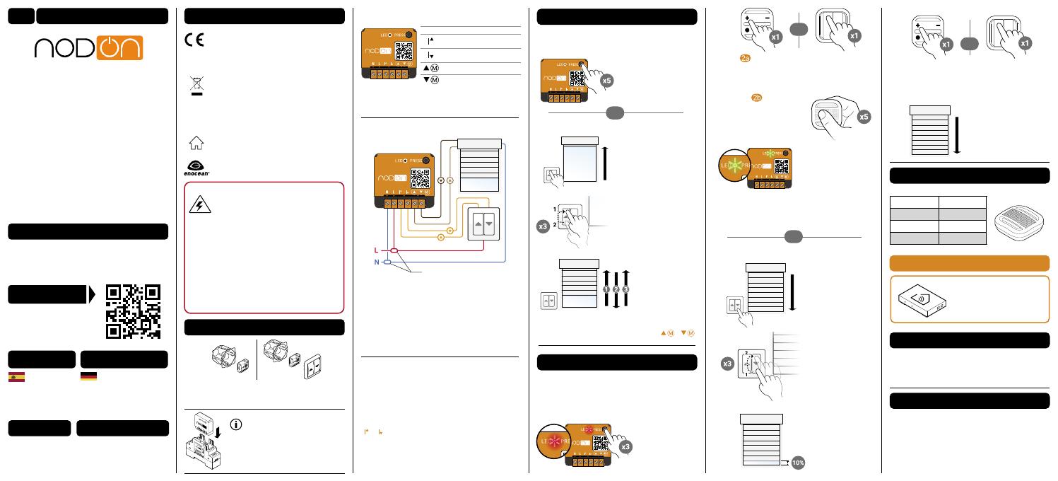
APPAIRAGE
DU MODULE VOLET ROULANT
Télécommande ou interrupteur :
Vous disposez de 30 secondes pour appairer votre contrôleur
en appuyant brièvement sur le bouton de votre choix (moins d’une
seconde), celui-ci pilotera la montée de votre volet roulant/store.
Ou
Ou
4 Télécommande ou interrupteur :
Vous disposez de 30 secondes pour appairer
votre contrôleur en appuyant brièvement sur le bouton
de votre choix (moins d’une seconde), celui-ci pilotera
la montée de votre volet roulant/store.
5 Le volet roulant/store
conrme l’appairage en se
fermant complètement.
3 Le volet roulant/store
monte de 10%.
2 Faites 3 fois la
séquence “Bas - Stop”
avec l’interrupteur laire.
1 Placez le volet
roulant/store en position
basse.
NOTICE
DÉTAILLÉE
Accédez directement à la notice
détaillée sur la rubrique support
sur nodon.fr/support/
INSTRUCCIONES
DE USO GEBRAUCHSANWEISUNG
Acceda directa-
mente a las
instrucciones detalladas
en la página de soporte de
nodon.fr/es/soporte/
Gehen Sie direkt zur
ausführlichen Anleitung
im Support Bereich unter
nodon.fr/de/technische-
unterstuetzung/
Type d’appui Mode
Appui simple Inversion
Appui double Ouvert
Appui long Fermé
Le module doit être raccordé et sous tension.
1 Appuyez plus de 5 secondes sur le bouton du module.
La LED scintille en orange.
2 Appuyez à nouveau sur le bouton (impulsion brève)
pour valider la réinitialisation. Si la réinitialisation se déroule
correctement, la LED clignote alternativement en rouge
et en vert, puis redevient verte. Recommencez si nécessaire.
3 Votre module a retrouvé sa conguration d’origine.
Effectuez la procédure identique à l’appairage (voir “appairage
du Module Multifonction”) en prenant soin d’appuyer sur le
bouton préalablement choisi pour contrôler votre portail/porte
de garage/gâche électrique ou votre prise électrique.
1 Coupez le courant.
2 Démontez l’interrupteur laire qui pilote le volet roulant/
store que vous souhaitez raccorder.
3 Câblez le module selon le schéma en gure 1.
4 Remontez l’interrupteur laire.
5 Remettez le courant.
Note: La même conguration est appliquée pour les 2 entrées
( et ). Il n’est pas possible de combiner un interrupteur
basculant avec un interrupteur poussoir. Pour relancer
l’autodétection, il est nécessaire de réinitialiser
manuellement le Module Volet Roulant (voir procédure de
réinitilalisation du module).
Le module doit être raccordé et sous tension.
Deux modes:
1. Depuis le module connecté
2. Depuis l’interrupteur laire
Pour ajouter une télécommande/interrupteur/Soft Button
(compatible EnOcean) vous devez entrer en mode appairage.
Le module doit être raccordé et sous tension.
Deux modes:
1. Depuis le module connecté
1 Lancez l’appairage
en effectuant 3 appuis
consécutifs rapides sur
le bouton du module.
La LED scintille en
rouge.
Note: Si la LED scintille orange pendant la procédure d’appairage,
cela signie que plus de 22 contrôleurs sont appairés et qu’aucun
autre contrôleur ne peut l’être. Vous devez donc supprimer un
contrôleur pour pouvoir en ajouter un nouveau.
3 La LED du module
scintille 2 fois en vert,
conrmant l’appairage
des deux appareils.
Soft Button :
Vous disposez de
30 secondes pour appairer
votre Soft Button en effectuant
5 appuis courts consécutifs sur
votre bouton.
2. Depuis l’interrupteur laire
ASTUCE


