Allen Bradley Allen-Bradley 1734-OB2 POINT I/O Output Module Manuel utilisateur
- Taper
- Manuel utilisateur

Installation Instructions
Original Instructions
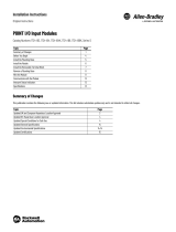
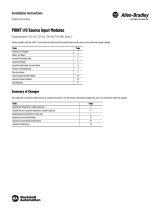
POINT I/O Output Module
Catalog Numbers 1734-OB2, 1734-OB4, 1734-OB4K, 1734-OB8, 1734-OB8K, Series C
Catalog numbers with the suffix ‘K’ are conformal coated and their specifications are the same as non-conformal coated catalogs.
Summary of Changes
This publication contains the following new or updated information. This list includes substantive updates only and is not intended to reflect all changes.
Topic Page
Summary of Changes 1
Before You Begin 5
Install the Mounting Base 5
Install the Module 6
Install the Removable Terminal Block 6
Remove a Mounting Base 7
Communicate with the Module 7
Wire the Modules 8
Interpret Status Indicators 11
Specifications 12
Topic Page
Updated template throughout
Updated UK and European Hazardous Location Approval 4
Updated IEC Hazardous Location Approval 4
Updated Special Conditions for Safe Use 4
Updated I/O status descriptions 11
Updated General Specifications 12
Updated Environmental Specifications 12, 13
Updated Certifications 13

2Rockwell Automation Publication 1734-IN018E-EN-E - September 2022
POINT I/O Output Module Installation Instructions
ATTENTION: Read this document and the documents listed in the Additional Resources section about installation, configuration and operation of this equipment before you install, configure, operate or maintain
this product. Users are required to familiarize themselves with installation and wiring instructions in addition to requirements of all applicable codes, laws, and standards.
Activities including installation, adjustments, putting into service, use, assembly, disassembly, and maintenance are required to be carried out by suitably trained personnel in accordance with applicable code of
practice. If this equipment is used in a manner not specified by the manufacturer, the protection provided by the equipment may be impaired.
ATENCIÓN: Antes de instalar, configurar, poner en funcionamiento o realizar el mantenimiento de este producto, lea este documento y los documentos listados en la sección Recursos adicionales acerca de la
instalación, configuración y operación de este equipo. Los usuarios deben familiarizarse con las instrucciones de instalación y cableado y con los requisitos de todos los códigos, leyes y estándares vigentes.
El personal debidamente capacitado debe realizar las actividades relacionadas a la instalación, ajustes, puesta en servicio, uso, ensamblaje, desensamblaje y mantenimiento de conformidad con el código de
práctica aplicable. Si este equipo se usa de una manera no especificada por el fabricante, la protección provista por el equipo puede resultar afectada.
ATENÇÃO: Leia este e os demais documentos sobre instalação, configuração e operação do equipamento que estão na seção Recursos adicionais antes de instalar, configurar, operar ou manter este produto. Os
usuários devem se familiarizar com as instruções de instalação e fiação além das especificações para todos os códigos, leis e normas aplicáveis.
É necessário que as atividades, incluindo instalação, ajustes, colocação em serviço, utilização, montagem, desmontagem e manutenção sejam realizadas por pessoal qualificado e especializado, de acordo com o
código de prática aplicável.
Caso este equipamento seja utilizado de maneira não estabelecida pelo fabricante, a proteção fornecida pelo equipamento pode ficar prejudicada.
ВНИМАНИЕ: Перед тем как устанавливать, настраивать, эксплуатировать или обслуживать данное оборудование, прочитайте этот документ и документы,
перечисленные в разделе «Дополнительные ресурсы». В этих документах изложены сведения об установке, настройке и эксплуатации данного оборудования.
Пользователи обязаны ознакомиться с инструкциями по установке и прокладке соединений, а также с требованиями всех применимых норм, законов и
стандартов.
Все действия, включая установку, наладку, ввод в эксплуатацию, использование, сборку, разборку и техническое обслуживание, должны выполняться
обученным персоналом в соответствии с применимыми нормами и правилами.
Если оборудование используется не предусмотренным производителем образом, защита оборудования может быть нарушена.
:
ACHTUNG: Lesen Sie dieses Dokument und die im Abschnitt „Weitere Informationen“aufgeführten Dokumente, die Informationen zu Installation, Konfiguration und Bedienung dieses Produkts enthalten, bevor Sie
dieses Produkt installieren, konfigurieren, bedienen oder warten. Anwender müssen sich neben den Bestimmungen aller anwendbaren Vorschriften, Gesetze und Normen zusätzlich mit den Installations- und
Verdrahtungsanweisungen vertraut machen.
Arbeiten im Rahmen der Installation, Anpassung, Inbetriebnahme, Verwendung, Montage, Demontage oder Instandhaltung dürfen nur durch ausreichend geschulte Mitarbeiter und in Übereinstimmung mit den
anwendbaren Ausführungsvorschriften vorgenommen werden.
Wenn das Gerät in einer Weise verwendet wird, die vom Hersteller nicht vorgesehen ist, kann die Schutzfunktion beeinträchtigt sein.
ATTENTION : Lisez ce document et les documents listés dans la section Ressources complémentaires relatifs à l’installation, la configuration et le fonctionnement de cet équipement avant d’installer, configurer,
utiliser ou entretenir ce produit. Les utilisateurs doivent se familiariser avec les instructions d’installation et de câblage en plus des exigences relatives aux codes, lois et normes en vigueur.
Les activités relatives à l’installation, le réglage, la mise en service, l’utilisation, l’assemblage, le démontage et l’entretien doivent être réalisées par des personnes formées selon le code de pratique en vigueur.
Si cet équipement est utilisé d’une façon qui n’a pas été définie par le fabricant, la protection fournie par l’équipement peut être compromise.
: , , , . ,
.
, , , , , , .
.
ATTENZIONE Prima di installare, configurare ed utilizzare il prodotto, o effettuare interventi di manutenzione su di esso, leggere il presente documento ed i documenti elencati nella sezione “Altre risorse”,
riguardanti l’installazione, la configurazione ed il funzionamento dell’apparecchiatura. Gli utenti devono leggere e comprendere le istruzioni di installazione e cablaggio, oltre ai requisiti previsti dalle leggi, codici e
standard applicabili.
Le attività come installazione, regolazioni, utilizzo, assemblaggio, disassemblaggio e manutenzione devono essere svolte da personale adeguatamente addestrato, nel rispetto delle procedure previste.
Qualora l’apparecchio venga utilizzato con modalità diverse da quanto previsto dal produttore, la sua funzione di protezione potrebbe venire compromessa.
DİKKAT: Bu ürünün kurulumu, yapılandırılması, işletilmesi veya bakımı öncesinde bu dokümanı ve bu ekipmanın kurulumu, yapılandırılması ve işletimi ile ilgili İlave Kaynaklar bölümünde yer listelenmiş
dokümanları okuyun. Kullanıcılar yürürlükteki tüm yönetmelikler, yasalar ve standartların gereksinimlerine ek olarak kurulum ve kablolama talimatlarını da öğrenmek zorundadır.
Kurulum, ayarlama, hizmete alma, kullanma, parçaları birleştirme, parçaları sökme ve bakım gibi aktiviteler sadece uygun eğitimleri almış kişiler tarafından yürürlükteki uygulama yönetmeliklerine uygun şekilde
yapılabilir.
Bu ekipman üretici tarafından belirlenmiş amacın dışında kullanılırsa, ekipman tarafından sağlanan koruma bozulabilir.
岤䠑✲갪㖈㸞酤鏤㹁乽⡲䧴笞隌劥欴ㅷ锞⯓ꠗ隡姽俒⟝⟃⿻倴 չⰦ➮须彂պ畎眏⚥剤ꡠ㸞酤鏤㹁莅乽⡲姽鏤⪔涸俒⟝⢪欽罏䗳갭擿䜫㸞酤ㄤꂂ箁䭸
爚⚛痘ざ䨾剤岁鋊岁䖒ㄤ垦彋銴宠
⺫䭍㸞酤锅侮❜➰⢪欽⢪欽穉酤䬓⽹ㄤ笞隌瘞⹛⡲鿪䗳갭❜歋䊺竤麕黠殹鎯箻涸➃㆞鹎遤⟃痘ざ黠欽涸㻜⡲岁鋊
㥶卓㼟鏤⪔欽倴ꬌ醢鸤㉂䭸㹁涸欽鸁儘〳腋剚鸤䧭鏤⪔䨾䲿⣘涸⥃隌⸆腋「䴦
POZOR: Než začnete instalovat, konfigurovat či provozovat tento výrobek nebo provádět jeho údržbu, přečtěte si tento dokument a dokumenty uvedené v části Dodatečné zdroje ohledně instalace, konfigurace
a provozu tohoto zařízení. Uživatelé se musejí vedle požadavků všech relevantních vyhlášek, zákonů anorem nutně seznámit také s pokyny pro instalaci a elektrické zapojení.
Činnosti zahrnující instalaci, nastavení, uvedení do provozu, užívání, montáž, demontáž a údržbu musí vykonávat vhodně proškolený personál v souladu s příslušnými prováděcími předpisy.
Pokud se toto zařízení používá způsobem neodpovídajícím specifikaci výrobce, může být narušena ochrana, kterou toto zařízení poskytuje.
UWAGA: Przed instalacją, konfiguracją, użytkowaniem lub konserwacją tego produktu należy przeczytać niniejszy dokument oraz wszystkie dokumenty wymienione w sekcji Dodatkowe źródła omawiające
instalację, konfigurację i procedury użytkowania tego urządzenia. Użytkownicy mają obowiązek zapoznać się z instrukcjami dotyczącymi instalacji oraz oprzewodowania, jak również z obowiązującymi kodeksami,
prawem i normami.
Działania obejmujące instalację, regulację, przekazanie do użytkowania, użytkowanie, montaż, demontaż oraz konserwację muszą być wykonywane przez odpowiednio przeszkolony personel zgodnie z
obowiązującym kodeksem postępowania.
Jeśli urządzenie jest użytkowane w sposób inny niż określony przez producenta, zabezpieczenie zapewniane przez urządzenie może zostać ograniczone.
OBS! Läs detta dokument samt dokumentet, som står listat i avsnittet Övriga resurser, om installation, konfigurering och drift av denna utrustning innan du installerar, konfigurerar eller börjar använda eller utföra
underhållsarbete på produkten. Användare måste bekanta sig med instruktioner för installation och kabeldragning, förutom krav enligt gällande koder, lagar och standarder.
Åtgärder som installation, justering, service, användning, montering, demontering och underhållsarbete måste utföras av personal med lämplig utbildning enligt lämpligt bruk.
Om denna utrustning används på ett sätt som inte anges av tillverkaren kan det hända att utrustningens skyddsanordningar försätts ur funktion.
LET OP: Lees dit document en de documenten die genoemd worden in de paragraaf Aanvullende informatie over de installatie, configuratie en bediening van deze apparatuur voordat u dit product installeert,
configureert, bediend of onderhoudt. Gebruikers moeten zich vertrouwd maken met de installatie en de bedradingsinstructies, naast de vereisten van alle toepasselijke regels, wetten en normen.
Activiteiten zoals het installeren, afstellen, in gebruik stellen, gebruiken, monteren, demonteren en het uitvoeren van onderhoud mogen uitsluitend worden uitgevoerd door hiervoor opgeleid personeel en in
overeenstemming met de geldende praktijkregels.
Indien de apparatuur wordt gebruikt op een wijze die niet is gespecificeerd door de fabrikant, dan bestaat het gevaar dat de beveiliging van de apparatuur niet goed werkt.

Rockwell Automation Publication 1734-IN018E-EN-E - September 2022 3
POINT I/O Output Module Installation Instructions
Environment and Enclosure
North American Hazardous Location Approval
ATTENTION: This equipment is intended for use in a Pollution Degree 2 industrial environment, in overvoltage Category II applications (as defined in EN/IEC
60664-1), at altitudes up to 2000 m (6562 ft) without derating.
This equipment is not intended for use in residential environments and may not provide adequate protection to radio communication services in such
environments.
This equipment is supplied as open-type equipment for indoor use. It must be mounted within an enclosure that is suitably designed for those specific
environmental conditions that will be present and appropriately designed to prevent personal injury resulting from accessibility to live parts. The enclosure
must have suitable flame-retardant properties to prevent or minimize the spread of flame, complying with a flame spread rating of 5V A or be approved for the
application if nonmetallic. The interior of the enclosure must be accessible only by the use of a tool. Subsequent sections of this publication may contain more
information regarding specific enclosure type ratings that are required to comply with certain product safety certifications.
In addition to this publication, see the following:
• Industrial Automation Wiring and Grounding Guidelines, publication 1770-4.1, for additional installation requirements.
• NEMA Standard 250 and EN/IEC 60529, as applicable, for explanations of the degrees of protection provided by enclosures.
ATTENTION: Before installing, configuring, operating, or maintaining this product, users are required to familiarize themselves with installation and wiring
instructions in addition to requirements of all applicable codes, laws, and standards.
Installation, adjustments, putting into service, use, assembly, disassembly, and maintenance are required to be carried out by suitably trained personnel in
accordance with applicable code of practice. In case of malfunction or damage, no attempts at repair should be made. The module should be returned to the
manufacturer for repair. Do not dismantle the module.
The Following Information Applies When Operating This Equipment In
Hazardous Locations. Informations sur l’utilisation de cet équipement en environnements dangereux.
Products marked "CL I, DIV 2, GP A, B, C, D" are suitable for use in Class I Division 2
Groups A, B, C, D, Hazardous Locations and nonhazardous locations only. Each
product is supplied with markings on the rating nameplate indicating the
hazardous location temperature code. When combining products within a system,
the most adverse temperature code (lowest "T" number) may be used to help
determine the overall temperature code of the system. Combinations of equipment
in your system are subject to investigation by the local Authority Having
Jurisdiction at the time of installation.
Les produits marqués "CL I, DIV 2, GP A, B, C, D" ne conviennent qu'à une utilisation en
environnements de Classe I Division 2 Groupes A, B, C, D dangereux et non dangereux.
Chaque produit est livré avec des marquages sur sa plaque d'identification qui indiquent le
code de température pour les environnements dangereux. Lorsque plusieurs produits sont
combinés dans un système, le code de température le plus défavorable (code de
température le plus faible) peut être utilisé pour déterminer le code de température global
du système. Les combinaisons d'équipements dans le système sont sujettes à inspection
par les autorités locales qualifiées au moment de l'installation.
WARNING:
Explosion Hazard –
• Do not disconnect equipment unless power has been
removed or the area is known to be nonhazardous.
• Do not disconnect connections to this equipment
unless power has been removed or the area is known
to be nonhazardous. Secure any external connections
that mate to this equipment by using screws, sliding
latches, threaded connectors, or other means
provided with this product.
• Substitution of components may impair suitability for
Class I, Division 2.
AVERTISSEMENT:
Risque d’Explosion –
• Couper le courant ou s'assurer que l'environnement est
classé non dangereux avant de débrancher l'équipement.
• Couper le courant ou s'assurer que l'environnement est
classé non dangereux avant de débrancher les connecteurs.
Fixer tous les connecteurs externes reliés à cet équipement
à l'aide de vis, loquets coulissants, connecteurs filetés ou
autres moyens fournis avec ce produit.
• La substitution de composants peut rendre cet équipement
inadapté à une utilisation en environnement de Classe I,
Division 2.
WARNING: When used in a Class I, Division 2, hazardous location, this equipment must be mounted in a suitable enclosure with proper wiring method that complies
with the governing electrical codes.

4Rockwell Automation Publication 1734-IN018E-EN-E - September 2022
POINT I/O Output Module Installation Instructions
UK and European Hazardous Location Approval
IEC Hazardous Location Approval
Prevent Electrostatic Discharge
Special Conditions for Safe Use
The following applies to products marked II 3 G:
• Are intended for use in potentially explosive atmospheres as defined by UKEX regulation 2016 No. 1107 and European Union Directive 2014/34/EU and has been found to
comply with the Essential Health and Safety Requirements relating to the design and construction of Category 3 equipment intended for use in Zone 2 potentially explosive
atmospheres, given in Schedule 1 of UKEX and Annex II of this Directive.
• Compliance with the Essential Health and Safety Requirements has been assured by compliance with EN IEC 60079-7, and EN IEC 60079-0.
• Are Equipment Group II, Equipment Category 3, and comply with the Essential Health and Safety Requirements relating to the design and construction of such equipment
given in Schedule 1 of UKEX and Annex II of EU Directive 2014/34/EU. See the UKEx and EU Declaration of Conformity at rok.auto/certifications for details.
• The type of protection is Ex ec IIC T4 Gc according to EN IEC 60079-0:2018, EXPLOSIVE ATMOSPHERES - PART 0: EQUIPMENT - GENERAL REQUIREMENTS, Issue Date 07/2018, and
CENELEC EN IEC 60079-7:2015+A1:2018, Explosive atmospheres. Equipment protection by increased safety "e".
• Comply to Standard EN IEC 60079-0:2018, EXPLOSIVE ATMOSPHERES - PART 0: EQUIPMENT - GENERAL REQUIREMENTS, Issue Date 07/2018, and CENELEC EN IEC
60079-7:2015+A1:2018 Explosive atmospheres. Equipment protection by increased safety "e", reference certificate number DEMKO 04 ATEX 0330347X and UL22UKEX2478X.
• Are intended for use in areas in which explosive atmospheres caused by gases, vapors, mists, or air are unlikely to occur, or are likely to occur only infrequently and for short
periods. Such locations correspond to Zone 2 classification according to UKEX regulation 2016 No. 1107 and ATEX directive 2014/34/EU.
• May have catalog numbers followed by a "K" to indicate a conformal coating option.
WARNING:
• This equipment is not resistant to sunlight or other sources of UV radiation.
• This equipment shall be mounted in an UKEX/ATEX/IECEx Zone 2 certified enclosure with a minimum ingress protection rating of at least IP54 (in accordance
with EN/IEC 60079-0) and used in an environment of not more than Pollution Degree 2 (as defined in EN/IEC 60664-1) when applied in Zone 2 environments. The
enclosure must be accessible only by the use of a tool.
• This equipment shall be used within its specified ratings defined by Rockwell Automation.
• Transient protection shall be provided that is set at a level not exceeding 140% of the peak rated voltage at the supply terminals to the equipment.
• The instructions in the user manual shall be observed.
• This equipment must be used only with UKEX/ATEX/IECEx certified Rockwell Automation backplanes.
• Earthing is accomplished through mounting of modules on rail.
• Devices shall be used in an environment of not more than Pollution Degree 2.
The following applies to products with IECEx certification:
• Are intended for use in areas in which explosive atmospheres caused by gases, vapors, mists, or air are unlikely to occur, or are likely to occur only infrequently and for short
periods. Such locations correspond to Zone 2 classification to IEC 60079-0.
• The type of protection is Ex eC IIC T4 Gc according to IEC 60079-0 and IEC 60079-7.
• Comply to Standards IEC 60079-0, Explosive atmospheres ‐ Part 0: Equipment ‐ General requirements, Edition 7, Revision Date 2017 and IEC 60079-7, 5.1 Edition revision date
2017, Explosive atmospheres - Part 7: Equipment protection by increased safety "e", reference IECEx certificate number IECEx UL 20.0072X.
• May have catalog numbers followed by a "K" to indicate a conformal coating option.
ATTENTION: This equipment is sensitive to electrostatic discharge, which can cause internal damage and affect normal operation. Follow these guidelines
when you handle this equipment:
• Touch a grounded object to discharge potential static.
• Wear an approved grounding wriststrap.
• Do not touch connectors or pins on component boards.
• Do not touch circuit components inside the equipment.
• Use a static-safe workstation, if available.
• Store the equipment in appropriate static-safe packaging when not in use.
ATTENTION:
• This product is grounded through the DIN rail to chassis ground. Use zinc plated chromate-passivated steel DIN rail to assure proper grounding. The use of
other DIN rail materials (for example, aluminum or plastic) that can corrode, oxidize, or are poor conductors, can result in improper or intermittent grounding.
Secure DIN rail to mounting surface approximately every 200 mm (7.8 in.) and use end-anchors appropriately. Be sure to ground the DIN rail properly. See the
Industrial Automation Wiring and Grounding Guidelines, publication 1770-4.1, for more information.
• Do not remove or replace an Adapter Module while power is applied. Interruption of the backplane can result in unintentional operation or machine motion.
• Do not discard the end cap. Use this end cap to cover the exposed interconnections on the last mounting base on the DIN rail. Failure to do so could result in
equipment damage or injury from electric shock.
• If this equipment is used in a manner not specified by the manufacturer, the protection provided by the equipment may be impaired.

Rockwell Automation Publication 1734-IN018E-EN-E - September 2022 5
POINT I/O Output Module Installation Instructions
Electrical Safety Considerations
Before You Begin
You can use these Series C POINT I/O™ Output modules with DeviceNet® and PROFIBUS adapters. If you are using Studio 5000 Logix Designer® application version 20 or higher, you
can also use the Series C modules with ControlNet® and EtherNet/IP™ adapters.
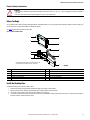
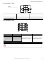
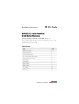
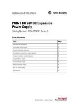
Use Figure 1 to identify the external features of the module.
Figure 1 - POINT I/O Output Module
Install the Mounting Base
To install the mounting base on the DIN rail, proceed as follows:
1. Position the mounting base vertically above the installed units (adapter, power supply, or existing module).
2. Slide the mounting base down allowing the interlocking side pieces to engage the adjacent module or adapter.
3. Press firmly to seat the mounting base on the DIN rail. The mounting base snaps into place.
4. To remove the mounting base from the DIN rail, remove the module and use a small bladed screwdriver to rotate the base locking screw to a vertical position. This releases
the locking mechanism. Then lift straight up to remove.
ATTENTION:
• This equipment is certified for use only within the surrounding air temperature range of -20…+55 °C (-4…+131 °F). The equipment must not be used outside of
this range.
• Use only a soft dry anti-static cloth to wipe down equipment. Do not use any cleaning agents.
Description Description
1 Module locking mechanism 6 Mounting base
2 Slide-in writable label 7 Interlocking side pieces
3 Insertable I/O module 8 Mechanical keying (orange)
4 Removable terminal block handle 9 DIN rail locking screw (orange)
5 Removable terminal block 10 Module wiring diagram
24VDC
Source
Output
Module
Status
Network
Status
1734
OB4
NODE:
0
1
2
3
1
10
9
8
7
2
4
5
6
3
The wiring base assembly consists of a mounting base, 1734-MB,
and a Removable Terminal Block, 1734-RTB, or 1734-RTBS.
1734-OB4

6Rockwell Automation Publication 1734-IN018E-EN-E - September 2022
POINT I/O Output Module Installation Instructions
Install the Module
The module can be installed before or after base installation. Make sure that the mounting base is correctly keyed before installing the module into the mounting base. In addition,
make sure that the mounting base locking screw is positioned horizontal referenced to the base.
To install the module, proceed as follows.
1. Using a bladed screwdriver, rotate the keyswitch on the mounting base clockwise until the number required for the type of module being installed aligns with the notch in
the base.
2. Verify that the DIN rail locking screw is in the horizontal position. You cannot insert the module if the locking mechanism is unlocked.
3. Insert the module straight down into the mounting base.
4. Press to secure. The module locks into place.
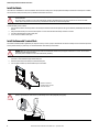
Install the Removable Terminal Block
A Removable Terminal Block (RTB) is supplied with your wiring base assembly. To remove, pull up on the RTB handle. This allows the mounting base to be removed and replaced as
necessary without removing any of the wirings. To reinsert the Removable Terminal Block, proceed as follows.
1. Insert the end opposite the handle into the base unit.
This end has a curved section that engages with the wiring base.
2. Rotate the terminal block into the wiring base until it locks itself in place.
3. If an I/O module is installed, snap the RTB handle into place on the module.
WARNING: When you insert or remove the module while backplane power is on, an electrical arc can occur. This could cause an explosion in hazardous
location installations.
Be sure that power is removed or the area is nonhazardous before proceeding. Repeated electrical arcing causes excessive wear to contacts on both the
module and its mating connector. Worn contacts may create electrical resistance that can affect module operation.
WARNING: When you connect or disconnect the Removable Terminal Block (RTB) with field-side power applied, an electrical arc can occur. This can cause an
explosion in hazardous location installations.
Be sure that power is removed or the area is nonhazardous before proceeding.
WARNING: For 1734-RTBS and 1734-RTB3S, to latch and unlatch the wire, insert a bladed screwdriver (catalog number 1492-N90 – 3 mm diameter blade) into the
opening at approximately 73° (blade surface is parallel with top surface of the opening) and push up gently.
0
1
Hook the RTB end into the
mounting base end, and rotate
until it locks into place.
73° 85°

Rockwell Automation Publication 1734-IN018E-EN-E - September 2022 7
POINT I/O Output Module Installation Instructions
Remove a Mounting Base
To remove a mounting base, you must remove any installed module and the module that is installed in the base to the right. Remove the Removable Terminal Block, if wired.
1. Unlatch the RTB handle on the I/O module.
2. Pull on the RTB handle to remove the Removable Terminal Block.
3. Press the module lock on the top of the module.
4. Pull on the I/O module to remove from the base.
5. Repeat steps 1, 2, 3 and 4 for the module to the right.
6. Use a small bladed screwdriver to rotate the orange base locking screw to a vertical position. This releases the locking mechanism.
7. Lift straight up to remove.
Communicate with the Module
I/O messages are sent to (consumed) and received from (produced) the POINT I/O modules. These messages are mapped onto the memory of the processor. This POINT I/O output
module consumes 1 byte of I/O data (scanner Tx).
WARNING: For 1734-TOPS and 1734-TOP3S, to latch and unlatch the wire, insert a bladed screwdriver (catalog number 1492-N90 – 3 mm diameter) into the opening
at approximately 97° (blade surface is parallel with top surface of the opening) and press in (do not push up or down).
Default Data Map for 1734-OB2
Message size: 1 Byte
76543210
Consumes (scanner Tx) Not used Ch1 Ch0 Channel state
Where: 0 = Off, 1 = On
Default Data Map for 1734-OB4, 1734-OB4K
Message size: 1 Byte
76543210
Consumes (scanner Tx) Not used Ch3 Ch2 Ch1 Ch0 Channel state
Where: 0 = Off, 1 = On
Default Data Map for 1734-OB8, 1734-OB8K
Message size: 1 Byte
76543210
Consumes (scanner Tx) Ch7 Ch6 Ch5 Ch4 Ch3 Ch2 Ch1 Ch0 Channel state
Where: 0 = off, 1 = on
97°

8Rockwell Automation Publication 1734-IN018E-EN-E - September 2022
POINT I/O Output Module Installation Instructions
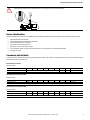
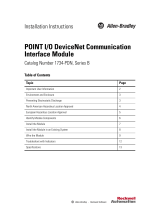
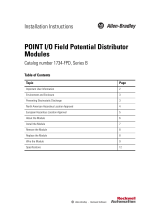
Wire the Modules
To wire the modules, see Figure 2, Figure 3, Figure 4, Figure 5, and Figure 6.
Figure 2 - POINT I/O Output Modules
Figure 3 - Output Module 1734-OB2
WARNING: If you connect or disconnect wiring while the field-side power is on, an electrical arc can occur. This could cause an explosion in hazardous location
installations. Be sure that power is removed or the area is nonhazardous before proceeding.
Channel Number Output Terminal Common Terminal Power
Channel 0 0, 2 4 6
Channel 1 1, 3 5 7
Module power is supplied by the internal power bus.
24VDC
Source
Output
Module
Status
Network
Status
1734
OB2
0
1
NODE:
24VDC
Source
Output
Module
Status
Network
Status
1734
OB4
0
1
2
3
NODE:
24VDC
Source
Output
Module
Status
Network
Status
1734
OB8
0
1
2
3
NODE:
4
5
6
7
CC
VV
Output 2
CC
CC
Output 2
C = Common
V = Supply
1734-OB2 1734-OB4,
1734-OB4K
1734-OB8,
1734-OB8K
Output 0Output 1Output 0Output 0 Output 1Output 1
Output 0 Output 1 Output 3 Output 3
Output 4 Output 5
Output 6 Output 7
Out 1
Out 0
Load
1
0
Out 1
Out 0
3
2
C
C
5
4
V
V
7
6
Load
V = 12/24V DC
C = Common
Field power is supplied by the internal power bus

Rockwell Automation Publication 1734-IN018E-EN-E - September 2022 9
POINT I/O Output Module Installation Instructions
Figure 4 - Output Module 1734-OB4, 1734-OB4K
Figure 5 - Output Module 1734-OB8, 1734-OB8K
Channel Number Output Terminal Common Terminal
Channel 0 0 6
Channel 1 1 7
Channel 2 2 4
Channel 3 3 5
Module power is supplied by the internal power bus.
Channel Number Output Terminal Common Terminal Power
Channel 0 0
Common is daisy chained from either a 1734 adapter,
1734-FPD, 1734-EP24DC or from a user-supplied
external terminal block.
The 24V DC power for the module is supplied by the
internal power bus and originates from the same
adapter, 1734-FPD, or 1734-EP24DC as common.
Channel 1 1
Channel 2 2
Channel 3 3
Channel 4 4
Channel 5 5
Channel 6 6
Channel 7 7
Module power is supplied by the internal power bus.
WARNING: Do not wire more than two conductors on any single terminal.
Out 1
Out 0
1
0
Out 3
Out 2
3
2
C
C
5
4
C
C
7
6
LoadLoad
V=12/24V DC
C = Common
Field power is supplied by the internal power bus
Load
Load
Out 1
Out 0 Load
1
0
Out 3
Out 2 3
2
Out 5Out 4
5
4
Out 7Out 6
7
6
Load
Load
Load
Load
Load
Load
Load
CC

10 Rockwell Automation Publication 1734-IN018E-EN-E - September 2022
POINT I/O Output Module Installation Instructions
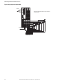
Figure 6 - Wiring Example for 1734-OB8, 1734-OB8K
System
Power
DeviceNet
Power
Network
Status
Module
Status
1734
IB8
3
2
0
1
7
6
4
5
Network
Status
Module
Status
1734
OB8
3
2
0
1
7
6
4
5
Load
Load
Load
Load
Load
Load
Load
Load
DeviceNet
24V DC return
24V DC
Terminal block with bus
connector strip
Note: The 1734-OB8 maximum load is 1 A max per channel and
3 A total per module.

Rockwell Automation Publication 1734-IN018E-EN-E - September 2022 11
POINT I/O Output Module Installation Instructions
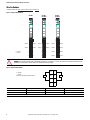
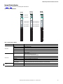
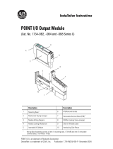
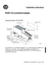
Interpret Status Indicators
See Figure 7 and Table 1 for information on how to interpret the status indicators.
Figure 7 - POINT I/O Output Modules
Table 1 - Indicator Status for Modules
Status Description
Module status
Off No power applied to device.
Green Device operating normally.
Flashing green Device needs commissioning due to missing, incomplete, or incorrect configuration.
Flashing red Recoverable fault.
Red Unrecoverable fault – may require device replacement.
Flashing red/green Device is in self-test mode.
Network status
Off Device is not online:
– Device has not completed dup_MAC-id test.
– Device not powered – check Module Status indicator.
Flashing green Device is online but has no connections in the established state.
Green Device is online and has connections in the established state.
Flashing red One or more I/O connections are in timed-out state.
Red Critical link failure – failed communication device. Device detected error that prevents it from communicating on the network.
Flashing red/green Communication faulted device – the device has detected a network access error and is in communication faulted state. Device
has received and accepted an Identity Communication Faulted Request – long protocol message.
I/O status Off The corresponding channel output is inactive.
Yellow The corresponding channel output is active and under control.
24VDC
Source
Output
Module
Status
Network
Status
1734
OB2
0
1
NODE:
24VDC
Source
Output
Module
Status
Network
Status
1734
OB4
0
1
2
3
NODE:
24VDC
Source
Output
Module
Status
Network
Status
1734
OB8
0
1
2
3
NODE:
4
5
6
7
Module status
Network status
Status of Output 0
Status of Output 1
Status of Output 2
Status of Output 3
Status of Outputs 1 & 5
Status of Outputs 2 & 6
Status of Outputs 3 & 7
Status of Outputs 0 & 4
1734-OB2 1734-OB4,
1734-OB4K
1734-OB8,
1734-OB8K

12 Rockwell Automation Publication 1734-IN018E-EN-E - September 2022
POINT I/O Output Module Installation Instructions
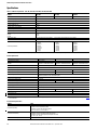
Specifications
Table 2 - POINT I/O Output Module – 1734-OB2, 1734-OB4, 1734-OB4K, 1734-OB8, 1734-OB8K
Attribute 1734-OB2 1734-OB4,
1734-OB4K 1734-OB8,
1734-OB8K
Outputs per module, non-isolated, sourcing 2 (1 group of 2) 4 (1 group of 4) 8 (1 group of 8)
On-state voltage range, min 10V DC
On-state voltage range, nom 24V DC
On-state voltage range, max 28.8V DC
On-state voltage drop, max 0.2V DC
On-state current, min per channel 1.0 mA
Off-state voltage, max 28.8V DC
Off-state leakage, max 0.5 mA
Output signal delay, max(1)
Off to On
On to Off
(1) Off to On delay is the time from a valid output "On" signal to output energization. On to Off delay is the time from a valid output "Off" signal to output de-energization.
0.1 ms
0.1 ms
Output current rating 1.0 A per output, 2.0 A max per module 1.0 A per output, not to exceed 3.0 A max per module
Surge current 2 A for 10 ms, repeatable every 3 s
Field wiring terminations
0 – Output 0
1 – Output 1
2 – Output 0
3 – Output 1
4 – Common
5 – Common
6 – Supply
7 – Supply
0 – Output 0
1 – Output 1
2 – Output 2
3 – Output 3
4 – Common
5 – Common
6 – Common
7 – Common
0 – Output 0
1 – Output 1
2 – Output 2
3 – Output 3
4 – Output 4
5 – Output 5
6 – Output 6
7 – Output 7
General Specifications
Attribute 1734-OB2 1734-OB4, 1734-OB4K 1734-OB8, 1734-OB8K
Terminal base screw torque 0.8 N•m (7 lb•in)
Indicators 2 yellow – output status
2 green/red – module/network status 4 yellow – output status
2 green/red – module/network status 8 yellow – output status
2 green/red – module/network status
Module location 1734-TB or 1734-TBS wiring base assembly
POINTBus™ current, max @ 5V DC 75 mA
Power dissipation, max @ 28.8V DC 0.8 W 1.2 W 2.0 W
Thermal dissipation, max @ 28.8V DC 2.7 BTU/hr 4.1 BTU/hr 6.8 BTU/hr
Isolation voltage 50V (continuous), reinforced insulation type
Type tested @ 2500V DC for 60 s, field-side to system
External DC power supply voltage, nom 24V DC
External DC power voltage range 10…28.8V DC
External DC power supply current 8 mA 16 mA 32 mA
Dimensions (H x W x D), approx. 56.0 x 12.0 x 75.5 mm (2.21 x 0.47 x 2.97 in.)
Wiring category(1)
(1) Use this Conductor Category information for planning conductor routing as described in the appropriate System Level Installation Manual. Also see the Industrial Automation Wiring and Grounding Guidelines, publication 1770-4.1,
for more information.
2 – on signal ports
Wire size Determined by installed terminal block
Weight, approx. 32.60 g (1.15 oz) 33.17 g (1.17 oz) 35.4 g (1.25 oz)
North American temp code T4A T4
UKEX/ATEX temp code T4
IECEx temp code T4
Environmental Specifications
Attribute Value
Temperature, operating
IEC 60068-2-1 (Test Ad, operating cold),
IEC 60068-2-2 (Test Bd, operating dry heat),
IEC 60068-2-14 (Test Nb, operating thermal shock):
-20 °C ≤ Ta ≤ +55 °C (-4 °F ≤ Ta ≤ +131 °F)
Temperature, nonoperating
IEC 60068-2-1 (Test Ab, unpackaged nonoperating cold),
IEC 60068-2-2 (Test Bb, unpackaged nonoperating dry heat),
IEC 60068-2-14 (Test Na, unpackaged nonoperating thermal shock):
-40…+85 °C (-40…+185 °F)
Temperature, surrounding air, max 55 °C (131 °F)

Rockwell Automation Publication 1734-IN018E-EN-E - September 2022 13
POINT I/O Output Module Installation Instructions
Relative humidity IEC 60068-2-30 (Test Db, unpackaged damp heat):
5…95% noncondensing
Vibration IEC 60068-2-6 (Test Fc, operating):
5 g @ 10…500 Hz
Shock, operating IEC 60068-2-27 (Test Ea, unpackaged shock):
30 g
Shock, nonoperating IEC 60068-2-27 (Test Ea, unpackaged shock):
50 g
Emissions IEC 61000-6-4
ESD immunity IEC 61000-4-2:
6 kV contact discharges
8 kV air discharges
Radiated RF immunity IEC 61000-4-3:
10V/m with 1 kHz sine-wave 80% AM from 80…6000 MHz
EFT/B immunity IEC 61000-4-4:
±2 kV at 5 kHz on power ports
±2 kV at 5 kHz on signal ports
Surge transient immunity IEC 61000-4-5:
±1 kV line-line (DM) and ±2 kV line-earth (CM) on signal ports
Conducted RF immunity IEC 61000-4-6:
10V rms with 1 kHz sine-wave 80% AM from 150 kHz...80 MHz
Enclosure type rating None (open-style)
Certifications
Certification (When Product Is Marked)(1) Value
c-UL-us UL Listed Industrial Control Equipment, certified for US and Canada. See UL File E65584.
UL Listed for Class I, Division 2 Group A,B,C,D Hazardous Locations, certified for U.S. and Canada. See UL File E194810.
UK and CE
UK Statutory Instrument 2016 No. 1091 and European Union 2014/30/EU EMC Directive, compliant with:
EN 61326-1; Measurement/Control/Laboratory use, Industrial requirements
EN 61000-6-2; Industrial Immunity
EN 61000-6-4; Industrial Emissions
EN 61131-2; Programmable Controllers (Clause 8, Zone A & B)
UK Statutory Instrument 2012 No. 3032 and European Union 2011/65/EU RoHS, compliant with:
EN IEC 63000; Technical documentation
RCM Australian Radiocommunications Act, compliant with:
AS/NZS CISPR 11; Industrial Emissions
Ex
UK Statutory Instrument 2016 No. 1107 and European Union 2014/34/EU ATEX Directive, compliant with:
EN IEC 60079-0; General Requirements
EN IEC 60079-7; Explosive Atmospheres, Protection "e"
II 3 G Ex ec IIC T4 Gc
DEMKO 04 ATEX 0330347X
UL22UKEX2478X
KC Korean Registration of Broadcasting and Communications Equipment, compliant with:
Article 58-2 of Radio Waves Act, Clause 3
EAC Russian Customs Union TR CU 020/2011 EMC Technical Regulation
Morocco Arrêté ministériel n° 6404-15 du 29 ramadan 1436
CCC CNCA-C23-01
CNCA-C23-01 CCC Implementation Rule Explosion-Proof Electrical Products
CCC: 2020122309111607
IECEx
IECEx System, compliant with:
IEC 60079-0; General Requirements
IEC 60079-7; Explosive Atmospheres, Protection "e"
II 3 G Ex ec IIC T4 Gc
IECEx UL 20.0072X
(1) See the Product Certification link at rok.auto/certifications for Declaration of Conformity, Certificates, and other certification details.
Environmental Specifications (Continued)
Attribute Value

Publication 1734-IN018E-EN-E - September 2022 | Supersedes Publication 1734-IN018D-EN-E - January 2019
Copyright © 2022 Rockwell Automation, Inc. All rights reserved.
Rockwell Otomasyon Ticaret A.Ş. Kar Plaza İş Merkezi E Blok Kat:6 34752 İçerenköy, İstanbul, Tel: +90 (216) 5698400 EEE Yönetmeliğine Uygundur
Allen-Bradley, expanding human possibility, FactoryTalk, POINT I/O, POINTBus, Rockwell Automation, Studio 5000 Logix Designer, and TechConnect are trademarks of Rockwell Automation, Inc.
ControlNet, DeviceNet, and EtherNet/IP are trademarks of ODVA, Inc.
Trademarks not belonging to Rockwell Automation are property of their respective companies.
Waste Electrical and Electronic Equipment (WEEE)
Rockwell Automation maintains current product environmental compliance information on its website at rok.auto/pec.
At the end of life, this equipment should be collected separately from any unsorted municipal waste.
Rockwell Automation Support
Use these resources to access support information.
Documentation Feedback
Your comments help us serve your documentation needs better. If you have any suggestions on how to improve our content, complete the form at rok.auto/docfeedback.
Technical Support Center Find help with how-to videos, FAQs, chat, user forums, Knowledgebase, and product notification updates. rok.auto/support
Local Technical Support Phone Numbers Locate the telephone number for your country. rok.auto/phonesupport
Technical Documentation Center Quickly access and download technical specifications, installation instructions, and user manuals. rok.auto/techdocs
Literature Library Find installation instructions, manuals, brochures, and technical data publications. rok.auto/literature
Product Compatibility and Download Center (PCDC) Download firmware, associated files (such as AOP, EDS, and DTM), and access product release notes. rok.auto/pcdc
-
 1
1
-
 2
2
-
 3
3
-
 4
4
-
 5
5
-
 6
6
-
 7
7
-
 8
8
-
 9
9
-
 10
10
-
 11
11
-
 12
12
-
 13
13
-
 14
14


Allen Bradley Allen-Bradley 1734-OB2 POINT I/O Output Module Manuel utilisateur
- Taper
- Manuel utilisateur
dans d''autres langues
Documents connexes
Autres documents
-
 Allen-Bradley 1734-EP24DCK Installation Instructions Manual
-
 Rockwell Automation Allen-Bradley POINT I/O 1734-FPDK Installation Instructions Manual
-
 Allen-Bradley POINT I/O 1734-PDN Installation Instructions Manual
-
 Allen-Bradley 1734-OB8 Installation Instructions Manual
-
 Allen-Bradley 1734-EP24DC Installation Instructions Manual
-
 Rockwell Automation Allen-Bradley POINT I/O 1734-FPD Installation Instructions Manual
-
 Allen-Bradley POINT I/O ControlNet 1734-ACNR Installation Instructions Manual
-
Allen-Bradley C Series Installation Instructions Manual
-
-
 Thermo Fisher Scientific Biogas 5000 Biogas Portable Gas Monitor Manuel utilisateur


