Rockwell Automation Allen-Bradley POINT I/O 1734-FPD Installation Instructions Manual
- Taper
- Installation Instructions Manual

Installation Instructions
POINT I/O Field Potential Distributor
Modules
Catalog number 1734-FPD, Series B
Table of Contents
Topic Page
Important User Information 2
Environment and Enclosure 3
Preventing Electrostatic Discharge 3
North American Hazardous Location Approval 4
European Hazardous Location Approval 5
About the Module 6
Install the Module 7
Remove the Module 8
Replace the Module 8
Wire the Module 9
Specifications 12

2 POINT I/O Field Potential Distributor Modules
Publication 1734-IN059D-EN-E - April 2013
Important User Information
Solid-state equipment has operational characteristics differing from those of electromechanical
equipment. Safety Guidelines for the Application, Installation and Maintenance of Solid State Controls
(Publication SGI-1.1
available from your local Rockwell Automation sales office or online at
http://www.rockwellautomation.com/literature/
) describes some important differences between
solid-state equipment and hard-wired electromechanical devices. Because of this difference, and also
because of the wide variety of uses for solid-state equipment, all persons responsible for applying this
equipment must satisfy themselves that each intended application of this equipment is acceptable.
In no event will Rockwell Automation, Inc. be responsible or liable for indirect or consequential damages
resulting from the use or application of this equipment.
The examples and diagrams in this manual are included solely for illustrative purposes. Because of the
many variables and requirements associated with any particular installation, Rockwell Automation, Inc.
cannot assume responsibility or liability for actual use based on the examples and diagrams.
No patent liability is assumed by Rockwell Automation, Inc. with respect to use of information, circuits,
equipment, or software described in this manual.
Reproduction of the contents of this manual, in whole or in part, without written permission of Rockwell
Automation, Inc., is prohibited.
Throughout this manual, when necessary, we use notes to make you aware of safety considerations.
WARNING: Identifies information about practices or circumstances that can cause an
explosion in a hazardous environment, which may lead to personal injury or death,
property damage, or economic loss.
ATTENTION: Identifies information about practices or circumstances that can lead to
personal injury or death, property damage, or economic loss. Attentions help you
identify a hazard, avoid a hazard and recognize the consequences.
SHOCK HAZARD: Labels may be on or inside the equipment (for example, drive or
motor) to alert people that dangerous voltage may be present.
BURN HAZARD: Labels may be on or inside the equipment (for example, drive or
motor) to alert people that surfaces may reach dangerous temperatures.
IMPORTANT Identifies information that is critical for successful application and understanding of
the product.

POINT I/O Field Potential Distributor Modules 3
Publication 1734-IN059D-EN-E - April 2013
Environment and Enclosure
Preventing Electrostatic Discharge
ATTENTION: This equipment is intended for use in a Pollution Degree 2
industrial environment, in overvoltage Category II applications (as defined in IEC
publication 60664-1), at altitudes up to 2000 meters (6562 ft) without derating.
This equipment is considered Group 1, Class A industrial equipment according
to IEC/CISPR Publication 11. Without appropriate precautions, there may be
potential difficulties ensuring electromagnetic compatibility in other
environments due to conducted as well as radiated disturbance.
This equipment is supplied as open-type equipment. It must be mounted within
an enclosure that is suitably designed for those specific environmental
conditions that will be present and appropriately designed to prevent personal
injury resulting from accessibility to live parts. The enclosure must have
suitable flame-retardant properties to prevent or minimize the spread of flame,
complying with a flame spread rating of 5VA, V2, V1, V0 (or equivalent) if
non-metallic. The interior of the enclosure must be accessible only by the use of
a tool. Subsequent sections of this publication may contain additional
information regarding specific enclosure type ratings that are required to
comply with certain product safety certifications.
In addition to this publication, see:
• Industrial Automation Wiring and Grounding Guidelines, for additional
installation requirements, Allen-Bradley publication 1770-IN041
.
• NEMA Standards publication 250 and IEC publication 60529, as applicable,
for explanations of the degrees of protection provided by different types of
enclosure.
ATTENTION: This equipment is sensitive to electrostatic discharge, which can
cause internal damage and affect normal operation. Follow these guidelines
when you handle this equipment:
• Touch a grounded object to discharge potential static.
• Wear an approved grounding wriststrap.
• Do not touch connectors or pins on component boards.
• Do not touch circuit components inside the equipment.
• Use a static-safe workstation, if available.
• Store the equipment in appropriate static-safe packaging when not in use.

4 POINT I/O Field Potential Distributor Modules
Publication 1734-IN059D-EN-E - April 2013
North American Hazardous Location Approval
The following information applies when
operating this equipment in hazardous
locations:
Informations sur l’utilisation de cet
équipement en environnements dangereux:
Products marked "CL I, DIV 2, GP A, B, C, D" are suitable for
use in Class I Division 2 Groups A, B, C, D, Hazardous
Locations and nonhazardous locations only. Each product is
supplied with markings on the rating nameplate indicating
the hazardous location temperature code. When combining
products within a system, the most adverse temperature code
(lowest "T" number) may be used to help determine the
overall temperature code of the system. Combinations of
equipment in your system are subject to investigation by the
local Authority Having Jurisdiction at the time of installation.
Les produits marqués "CL I, DIV 2, GP A, B, C, D" ne
conviennent qu'à une utilisation en environnements de
Classe I Division 2 Groupes A, B, C, D dangereux et non
dangereux. Chaque produit est livré avec des marquages
sur sa plaque d'identification qui indiquent le code de
température pour les environnements dangereux. Lorsque
plusieurs produits sont combinés dans un système, le code
de température le plus défavorable (code de température le
plus faible) peut être utilisé pour déterminer le code de
température global du système. Les combinaisons
d'équipements dans le système sont sujettes à inspection
par les autorités locales qualifiées au moment de
l'installation.
EXPLOSION HAZARD
• Do not disconnect equipment unless power
has been removed or the area is known to be
nonhazardous.
• Do not disconnect connections to this
equipment unless power has been removed
or the area is known to be nonhazardous.
Secure any external connections that mate
to this equipment by using screws, sliding
latches, threaded connectors, or other
means provided with this product.
• Substitution of components may impair
suitability for Class I, Division 2.
• If this product contains batteries, they must
only be changed in an area known to be
nonhazardous.
RISQUE D’EXPLOSION
• Couper le courant ou s'assurer que
l'environnement est classé non dangereux
avant de débrancher l'équipement.
• Couper le courant ou s'assurer que
l'environnement est classé non dangereux
avant de débrancher les connecteurs. Fixer
tous les connecteurs externes reliés à cet
équipement à l'aide de vis, loquets
coulissants, connecteurs filetés ou autres
moyens fournis avec ce produit.
• La substitution de composants peut rendre
cet équipement inadapté à une utilisation
en environnement de Classe I, Division 2.
• S'assurer que l'environnement est classé
non dangereux avant de changer les piles.

POINT I/O Field Potential Distributor Modules 5
Publication 1734-IN059D-EN-E - April 2013
European Hazardous Location Approval
The following applies when the product bears the Ex Marking
This equipment is intended for use in potentially explosive atmospheres as defined by
European Union Directive 94/9/EC.
DEMKO certifies that this equipment has been found to comply with the Essential Health
and Safety Requirements relating to the design and construction of Category 3 equipment
intended for use in Zone 2 potentially explosive atmospheres, given in Annex II to this
Directive.
Compliance with the Essential Health and Safety Requirements has been assured by
compliance with EN 60079-15.
ATTENTION: This equipment is not resistant to sunlight or other sources of
UV radiation.
WARNING: This equipment shall be mounted in an ATEX certified enclosure
with a minimum ingress protection rating of at least IP54 (as defined in
IEC60529) and used in an environment of not more than Pollution Degree 2
(as defined in IEC 60664-1) when applied in Zone 2 environments. The
enclosure must utilize a tool removable cover or door.
WARNING: This equipment shall be used within its specified ratings
defined by Rockwell Automation.
WARNING: Provision shall be made to prevent the rated voltage from being
exceeded by transient disturbances of more than 140% of the rated voltage
when applied in Zone 2 environments.
WARNING: Secure any external connections that mate to this equipment by
using screws, sliding latches, threaded connectors, or other means provided
with this product.
WARNING: Do not disconnect equipment unless power has been removed
or the area is known to be nonhazardous.

6 POINT I/O Field Potential Distributor Modules
Publication 1734-IN059D-EN-E - April 2013
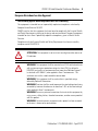
About the Module
The purpose of the POINT I/O™ Field Potential Distributormodule is to break the field
power distribution.
Use the module to change the field power distribution source for I/O modules to the right
of the module. This facilitates logical or functional partitioning of low-channel count,
high I/O-mix applications using the 1734-adapters, 1734-PDN, and 1734D Series
communication interfaces. This module passes through all POINT I/O backplane signals
except the internal field power bus for field devices.
You can use the module with a range of voltage inputs to include the following:
• 5…250V DC applications
• 24…240V AC applications
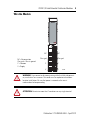
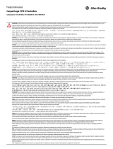
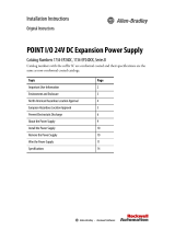
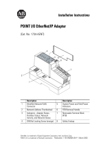
POINT I/O Field Potential Distributor Module
Description Description
1 Module label 4 Removable Terminal Block (RTB)
2 DIN rail locking screw (orange) 5 Interlocking side pieces
3 Removable Terminal Block handle
1
5
3
4
2
43974

POINT I/O Field Potential Distributor Modules 7
Publication 1734-IN059D-EN-E - April 2013
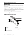
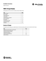
Install the Module
To install the module on the DIN rail, proceed as follows:
1. Position the module vertically above the DIN rail.
2. Engage the interlocking pieces with the unit on the left.
3. Press down firmly to install the module on the DIN rail. The locking mechanism
locks the module to the DIN rail.
ATTENTION: This product is grounded through the DIN rail to chassis ground.
Use zinc plated yellow-chromate steel DIN rail to assure proper grounding. The
use of other DIN rail materials (for example, aluminum or plastic) that can
corrode, oxidize, or are poor conductors, can result in improper or intermittent
grounding. Secure DIN rail to mounting surface approximately every 200 mm
(7.8 in.) and use end-anchors appropriately.
WARNING: When you insert or remove the module while backplane power is
on, an electrical arc can occur. This could cause an explosion in hazardous
location installations.
Be sure that power is removed or the area is nonhazardous before proceeding.
Repeated electrical arcing causes excessive wear to contacts on both the
module and its mating connector. Worn contacts may create electrical
resistance that can affect module operation.

8 POINT I/O Field Potential Distributor Modules
Publication 1734-IN059D-EN-E - April 2013
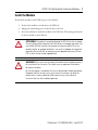
Remove the Module
To remove a 1734-FPD module, you must first remove any I/O module installed in the
base to the right. To remove the 1734-FPD module from the DIN rail, proceed as follows:
1. Pull up on the RTB removal handle to remove the terminal block.
2. Use a small-bladed screwdriver to rotate the DIN rail locking screw to a vertical
position. This releases the locking mechanism.
3. Lift straight up to remove.
Replace the Module
To install a replacement module in an existing system, proceed as follows:
1. Position the module vertically above the DIN rail.
2. Slide the module down to engage the interlocking sides pieces to the adjacent
modules on both the left and right sides.
3. Press down firmly to install the module on the DIN rail. The module locking
mechanism snaps into place.
WARNING: When you connect or disconnect the Removable Terminal Block
(RTB) with field side power applied, an electrical arc can occur. This could cause
an explosion in hazardous location installations.
Be sure that power is removed or the area is nonhazardous before proceeding.
45727

POINT I/O Field Potential Distributor Modules 9
Publication 1734-IN059D-EN-E - April 2013
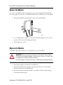
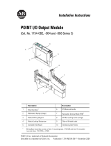
Wire the Module
WARNING: If you connect or disconnect wiring while the field-side power is
on, an electrical arc can occur. This could cause an explosion in hazardous
location installations. Be sure that power is removed or the area is
nonhazardous before proceeding.
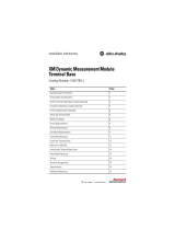
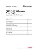
ATTENTION: Do not wire more than 2 conductors on any single terminal.
NC = No connection
Chas gnd = Chassis ground
C = Common
V = Supply
NC
Chas gnd
C
V
NC
C
V
Chas gnd
45728

10 POINT I/O Field Potential Distributor Modules
Publication 1734-IN059D-EN-E - April 2013
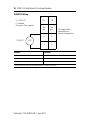
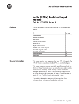
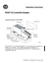
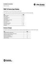
12/24V DC Wiring
Connect Terminal
+V DC 6
-V DC 4
Chas gnd 2
12/24V DC becomes the internal field power bus for modules to the right.
V DC
NC
NC
Chas
gnd
C
V
V
C
Chas
gnd
3
5
7
0
1
2
4
6
This supply will be
connected to the
internal field power bus.
V = 12/24V DC
C = Common
Chas gnd = Chassis ground
12/24V DC

POINT I/O Field Potential Distributor Modules 11
Publication 1734-IN059D-EN-E - April 2013
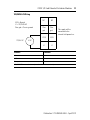
120/240V AC Wiring
Connect Terminal
L1 6
L2/N 4
Chas gnd 2
120/240V AC becomes the internal power bus for modules to the right.
V AC
NC
NC
Chas
gnd
L2/N
L1
L1
L2/N
Chas
gnd
3
5
7
0
1
2
4
6
This supply will be
connected to the
internal field power bus.
L2/N = Neutral
L1 = 120/240V AC
Chas gnd = Chassis ground
12/24V AC

12 POINT I/O Field Potential Distributor Modules
Publication 1734-IN059D-EN-E - April 2013
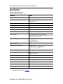
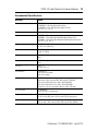
Specifications
General Specifications
Attribute Value
Terminal base screw torque 0.8 Nm (7 lb-in.)
Module location Between I/O modules in 1734 system
Breaks power bus
Indicators None
POINTBus current Pass through
Power consumption None
Power dissipation None
Thermal dissipation None
Isolation voltage 250V (continuous), Basic Insulation Type
Type tested @ 2600V DC for 60 s, User power to system,
User power to Chassis ground.
Input voltage rating 12V DC, 24V DC nom
10...28.8V DC range
120V AC, 240V AC nom
Input current, max 10 A
Field power bus supply voltage 264V AC max,
12V DC, 24V DC, 10...28.8V DC range
120V AC, 240V AC @ 50/60 Hz
Field power bus supply current, max 10 A
Dimensions, HxWxD 76.2 x 25.4 x 133.4 mm
(3.00 x 1.00 x 5.25 in.)
Wiring category
(1)
(1)
Use this conductor category information for planning conductor routing as described in Industrial Automation Wiring
and Grounding Guidelines, publication 1770-IN041.
1 – on power ports
Wire size Determined by installed terminal block
Weight (approx.) 0.12 kg (0.27 lb)
Enclosure type rating None (open-style)
North American temp code T4A
IEC temperature code T4

POINT I/O Field Potential Distributor Modules 13
Publication 1734-IN059D-EN-E - April 2013
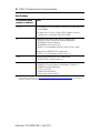
Environmental Specifications
Attribute Value
Temperature, operating IEC 60068-2-1 (Test Ad, Operating Cold),
IEC 60068-2-2 (Test Bd, Operating Dry Heat),
IEC 60068-2-14 (Test Nb, Operating Thermal Shock):
-20...55 °C (-4...131 °F)
Temperature, surrounding air, max 55 °C (131 °F)
Temperature, nonoperating IEC60068-2-1 (Test Ab, Unpackaged Nonoperating Cold)
IEC60068-2-2 (Test Bb, Unpackaged Nonoperating Dry Heat)
IEC60068-2-14 (Test Na, Unpackaged Nonoperating Thermal Shock):
-40...85 °C (-40...185 °F)
Relative humidity IEC 60068-2-30 (Test Db, Unpackaged Damp Heat):
5...95% non-condensing
Vibration IEC 60068-2-6 (Test Fc, Operating):
5 g @ 10...500 Hz
Shock, operating IEC60068-2-27 (Test Ea, Unpackaged Shock):
30 g
Shock, nonoperating IEC60068-2-27 (Test Ea, Unpackaged Shock):
50 g
Emissions CISPR 11:
Group 1, Class A
ESD immunity IEC61000-4-2:
6 kV contact discharges
8 kV air discharges
Radiated RF immunity IEC 61000-4-3:
10V/m with 1 kHz sine-wave 80% AM from 80...2000 MHz
10V/m with 200 Hz 50% Pulse 100% AM @ 900 MHz
10V/m with 200 Hz 50% Pulse 100% AM @ 1890 MHz
3V/m with 1 kHz sine-wave 80% AM from 2000...2700 MHz
EFT/B immunity IEC 61000-4-4:
±4 kV @ 2.5 kHz on power ports
Surge transient immunity IEC 61000-4-5:
±1 kV line-line (DM) and ±2 kV line-earth (CM) on power ports
Conducted RF immunity IEC61000-4-6:
10V rms with 1 kHz sine-wave 80% AM from 150 kHz...80 MHz

14 POINT I/O Field Potential Distributor Modules
Publication 1734-IN059D-EN-E - April 2013
Certifications
Certification (when
product is marked)
(1)
Value
c-UL-us UL-listed Industrial Control Equipment, certified for US and Canada. See
UL File E65584.
UL Listed for Class I, Division 2 Group A,B,C,D Hazardous Locations,
certified for U.S. and Canada. See UL File E194810.
CE European Union 89/336/EEC EMC Directive, compliant with:
EN 61326-1; Meas./Control/Lab., Industrial Requirements
EN 61000-6-2; Industrial Immunity
EN 61000-6-4; Industrial Emissions
EN 61131-2; Programmable Controllers (Clause 8, Zone A and B)
European Union 2006/95/EC LVD, compliant with:
EN 61131-2; Programmable Controllers (Clause 11)
C-Tick Australian Radiocommunications Act, compliant with:
AS/NZS CISPR 11; Industrial Emissions
Ex European Union 94/9/EC ATEX Directive, compliant with:
EN 60079-15; Potentially Explosive Atmospheres, Protection "n"
EN 60079-0; General Requirements
II 3 G Ex nA IIC T4 Gc
DEMKO 04 ATEX 0330347X
When used at or below 120V AC
(1)
See the Product Certification link at http://www.rockwellautomation.com/products/certification/ for Declaration of
Conformity, Certificates, and other certification details.

POINT I/O Field Potential Distributor Modules 15
Publication 1734-IN059D-EN-E - April 2013
Notes:

Rockwell Automation Support
Rockwell Automation provides technical information on the Web to assist you in using its products. At
http://www.rockwellautomation.com/support/
, you can find technical manuals, a knowledge base of FAQs,
technical and application notes, sample code and links to software service packs, and a MySupport feature
that you can customize to make the best use of these tools.
For an additional level of technical phone support for installation, configuration and troubleshooting, we
offer TechConnect support programs. For more information, contact your local distributor or Rockwell
Automation representative, or visit http://www.rockwellautomation.com/support/
.
Installation Assistance
If you experience a problem within the first 24 hours of installation, please review the information that's
contained in this manual. You can also contact a special Customer Support number for initial help in getting
your product up and running.
New Product Satisfaction Return
Rockwell Automation tests all of its products to ensure that they are fully operational when shipped from
the manufacturing facility. However, if your product is not functioning and needs to be returned, follow
these procedures.
Documentation Feedback
Your comments will help us serve your documentation needs better. If you have any suggestions on how to
improve this document, complete this form, publication RA-DU002
, available at
http://www.rockwellautomation.com/literature/
.
United States or Canada 1.440.646.3434
Outside United States or
Canada
Use the Worldwide Locator at
http://www.rockwellautomation.com/support/americas/phone_en.html
, or
contact your local Rockwell Automation representative.
United States Contact your distributor. You must provide a Customer Support case number
(call the phone number above to obtain one) to your distributor to complete
the return process.
Outside United States Please contact your local Rockwell Automation representative for the return
procedure.
Publication 1734-IN059D-EN-E - April 2013
Supersedes Publication 1734-IN059C-EN-P - June 2005 Copyright © 2013 Rockwell Automation, Inc. All rights reserved.
Allen-Bradley, Rockwell Automation, POINT I/O, and TechConnect are trademarks of Rockwell Automation, Inc.
Trademarks not belonging to Rockwell Automation are property of their respective companies.
-
 1
1
-
 2
2
-
 3
3
-
 4
4
-
 5
5
-
 6
6
-
 7
7
-
 8
8
-
 9
9
-
 10
10
-
 11
11
-
 12
12
-
 13
13
-
 14
14
-
 15
15
-
 16
16


Rockwell Automation Allen-Bradley POINT I/O 1734-FPD Installation Instructions Manual
- Taper
- Installation Instructions Manual
dans d''autres langues
Documents connexes
-
 Rockwell Automation Allen-Bradley POINT I/O 1734-FPDK Installation Instructions Manual
-
 Rockwell Automation Allen-Bradley CompactLogix 5370 L2 Series Information produit
-
 Rockwell Automation Allen-Bradley 1440-TBS-J Installation Instructions Manual
-
 Rockwell Automation 1771-ID16 Installation Instructions Manual


Autres documents
-
 Allen-Bradley POINT I/O 1734-PDN Installation Instructions Manual
-
 Allen-Bradley 1734-EP24DCK Installation Instructions Manual
-
 Allen-Bradley 1734-EP24DC Installation Instructions Manual
-
 Allen-Bradley POINT I/O ControlNet 1734-ACNR Installation Instructions Manual
-
 Allen-Bradley POINT I/O 1734-IE2C Installation Instructions Manual
-
Allen-Bradley C Series Installation Instructions Manual
-
 Allen Bradley Allen-Bradley 1734-IB2 POINT I/O Input Modules Manuel utilisateur
-
-
 Allen-Bradley 1734-OB8 Installation Instructions Manual
-
 Allen Bradley Allen-Bradley 1734-IV2 POINT I-O Source Input Modules Manuel utilisateur


