nVent RAYCHEM H59057 Single Entry Power Connection Manuel utilisateur
- Taper
- Manuel utilisateur

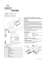
JBS-100-L-A
Single Entry Power Connection with Light and Junction Box
Installation Instructions
nVent.com
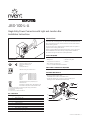
DESCRIPTION
The nVent RAYCHEM JBS-100-L-A is a Type 4X-rated power
connection kit. It is designed for use with nVent RAYCHEM BTV-CR,
BTV-CT, QTVR-CT, XTV-CT, KTV-CT, HTV-CT and VPL-CT industrial
parallel heating cables.
The kit includes plug-in LED light that indicates when the power is
supplied to the heating cable circuit.
This kit may be installed at temperatures as low as –40°F (–40°C). For
easier installation store above freezing until just before installation.
TOOLS REQUIRED
• Wire cutters • Adjustable pliers
• Utility knife • Needle nose pliers
• Large slotted screwdriver • Marker
• Wire stripper (for VPL-CT)
• 1/4 in or smaller flat-blade screwdriver
ADDITIONAL MATERIALS REQUIRED
OPTIONAL MATERIALS
• Recommended conduit drain:
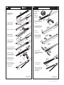
KIT CONTENTS
Item Qty Description
A 1 Stand assembly
B 1 Core sealer
C 1 Green/yellow tube
D 1 Cable lubricant
E 1 Cable tie
F 1 Lid
G 1 Box with terminal blocks
H 1 JBL-100-R plug-in light module
APPROVALS
A
D
G
F
E
B
C
H
(1)
®
Class I, Div. 2, Groups A, B, C, D
Class II, Div. 2, Groups E, F, G
Class III
CLI, ZN1, AEx em II T* (1)
(2)
(JBS-100-L-A only) Ex eb mb IIC T* Gb (2)
IECEx JBS-100-L-A is IECEx certified for use with:
BTV-CR/BTV-CT: IECEx BAS 20.0011X
QTVR-CT: IECEx BAS 20.0013X
XTV-CT: IECEx BAS 20.0012X
KTV-CT: IECEx BAS 20.0014X
HTV-CT: IECEx PTB 21.0007X
VPL-CT: IECEx BAS 20.0008X
(3) Class I Division 2 (Zone 2**), Groups A, B, C, D
Class I Zone 2 IIC
Ex eb mb IIC T* Gb; Class I Zone 1 AEx eb mb IIC T* Gb
Ex mb tb IIIC T*°C Db; Zone 21 AEx mb tb IIIC T*°C Db
*For system Temperature Code, see heating cable or design documentation
(1) Except VPL, HTV (FM approval only)
(2) Except KTV-CT
(3) For HTV-CT only ** Per CE Code Table 18
Hazardous Locations
nVent.com/RAYCHEM
|
1

This component is an electrical device that must be installed
correctly to ensure proper operation and to prevent shock or
fire. Read these important warnings and carefully follow all of
the installation instructions.
• To minimize the danger of fire from sustained electrical
arcing if the heating cable is damaged or improperly
installed, and to comply with the requirements of nVent,
agency certifications, and national electrical codes,
ground‑fault equipment protection must be used. Arcing
may not be stopped by conventional circuit breakers.
• Component approvals and performance are based on the
use of nVent‑specified parts only. Do not use substitute
parts or vinyl electrical tape.
• The black heating cable core and fibers are conductive and
can short. They must be properly insulated and kept dry.
• Damaged bus wires can overheat or short. Do not break bus
wire strands when scoring the jacket or core.
• Keep components and heating cable ends dry before and
during installation.
• Use only fire‑resistant insulation materials, such as
fiberglass wrap and flame‑retardant foam.
HEALTH HAZARD: Prolonged or repeated contact with the
sealant in the core sealer may cause skin irritation. Wash
hands thoroughly. Overheating or burning the sealant will
produce fumes that may cause polymer fume fever. Avoid
contamination of cigarettes or tobacco. Consult MSDS VEN
0058 for further information.
CHEMTREC 24‑hour emergency telephone:
(800) 424‑9300
Non‑emergency health and safety information:
Tel: (800) 545‑6258.
WARNING:
CAUTION:
nVent.com/RAYCHEM
Ce composant électrique doit être installé correctement pour
éviter les risques d'incendie ou de chocs électriques. Lire ces
avertissements importants et suivre attentivement toutes les
instructions d'installation.
• Pour réduire le danger d'incendie causé par un arc
électrique entretenu, si le câble chauffant est endommagé
ou mal installé, et pour respecter les exigences de nVent
et celles des codes applicables, il est impératif d'utiliser
une protection par disjoncteur différentiel. Les disjoncteurs
ordinaires ne sont pas toujours capables de supprimer les
arcs électriques.
• Les approbations et les performances des composants
sont basées sur l'utilisation des pièces nVent spécifiées
seulement. N'utilisez pas de pièces de rechange ou de
ruban isolant en vinyle.
• Le noyau et les fibres du câble chauffant noir sont
conducteurs et peuvent provoquer un court‑circuit. Ils
doivent être correctement isolés et gardés à sec.
• Les fils omnibus endommagés peuvent surchauffer ou subir
un court‑circuit.
• Ne brisez jamais les fils omnibus lorsque vous incisez la
gaine ou le noyau.
• Maintenez les composants et les extrémités des câbles
chauffants secs avant et pendant l'installation.
• Les fils omnibus peuvent provoquer un court‑circuit s'ils se
touchent. Les garder à l'écart les uns des autres
• N'utilisez que des matériaux isolants ininflammables,
par exemple une gaine de fibre de verre ou de la mousse
ignifuge.
• Laissez ces instructions d'installation à l'utilisateur pour
qu'il puisse les consulter.
DANGER POUR LA SANTÉ : Le contact prolongé ou répété
avec le produit d'étanchéité du noyau peut provoquer une
irritation de la peau. Lavez‑vous les mains soigneusement. La
surchauffe et la combustion du produit d'étanchéité produira
des vapeurs qui peuvent causer la fièvre des vapeurs de
polymères. Évitez la contamination des cigarettes ou du tabac.
Consultez la fiche technique santé‑sécurité (FTSS) VEN 0058
pour obtenir de plus amples informations.
Téléphone en cas d'urgence 24 heures sur 24 de CHEMTREC :
(800) 424‑9300
Renseignements non urgents en matière de santé et de
sécurité : (800) 545‑6258
AVERTISSEMENT: MISE EN GARDE:
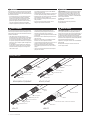
Clear jacket
Inner jacket
Braid
Outer
jacket
Heating element
Insulated bus wire
Bus wire connection
VPL-CT
Inner jacket
Outer jacket
Spacer
Conductive fiber
Bus wire
Braid
XTV-CT, KTV-CT
Bus wire
Conductive core
Inner jacket
Braid
Outer
jacket
BTV-CR, BTV-CT, QTVR-CT
HTV-CT
Outer Jacket
Braid
Conductive Core + Electrical Insulation
Bus Wire
Heating cable types

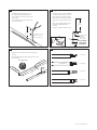
24 in
(60 cm)
12 in
(30 cm) 45°
Indentation (bus wire
connection on VPL
heating cables only).
7 1/2 in
(190 mm)
Do not cut braid.
XTV and KTV
BTV and QTVR
VPL
Go to Step 5B
Go to Step 5A
Go to Step 5C
Go to Step 5D
HTV
18 in
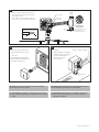
(45 cm)
Label on stand
indicates
direction of
box opening.
Drain
hole
of heating cable for installation. For
indentation.
for easier insertion.
• Lightly score outer jacket around and down as
shown.
• Bend heating cable to break jacket at score, then
peel off jacket.
• Optional: If stand is to be installed
on bottom side of pipe, knock out
drain hole prior to inserting cable.
• With label on stand facing desired
direction of box opening, push 18
in
stand. Use cable lubricant if
needed.
• Square off cable end with 90° cut.
• Do not attach
stand to pipe
until step 12.
1 2
3 4
nVent.com/RAYCHEM
|
3

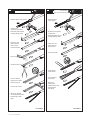
1/4 in
(5 mm)
6 1/2 in
(165 mm)
BTV and QTVR
6 1/2 in
(165 mm)
XTV and KTV
• Push braid back to create a pucker.
• At pucker use a
screwdriver to open braid.
• Bend heating cable and work
it through opening in braid.
• Lightly score inner
jacket around and
down as shown.
• Peel off inner jacket.
• Notch core.
• Peel bus wire from core.
• Score core between
buswires at inner jacket.
• Bend and snap core.
• Peel core from bus wire.
• Remove any remaining
core material from bus wires.
• Pull braid tight to make
pigtail.
• Push braid back to
create a pucker.
• At pucker use a screwdriver
to opwen braid.
• Bend heating cable and work
it through opening in braid.
• Lightly score inner
jacket around and
down as shown.
• Peel off inner jacket.
• Cut and remove
all fiber strands.
• Score and remove
center spacer.
• Remove any
remaining fiber
material from bus wires.
• Pull braid tight to
make pigtail.
Go to Step 6 Go to Step 6
5A 5B
4 | nVent.com/RAYCHEM

1/2 in
(13 mm)
6 in
(152 mm)
6 in
(152 mm)
VPL
• Push braid back
and bunch as tight
as possible.
• Lightly score inner
jacket around and
down as shown.
• Peel off inner jacket.
• Unwind heating
element, cut and
remove as shown.
• Lightly score clear
jacket around and
down as shown.
• Bend heating cable to
break jacket at the score
then peel off jacket.
• Push braid forward.
Use a screwdriver to
open braid as shown.
• Bend heating cable
and work it through
opening in braid.
• Remove insulation
from ends of bus wires.
• Pull braid tight to
make pigtail.
Go to Step 6
5C
6 1/2 inches
(165 mm)
180°
180°
6 1/2 inches
(165 mm)
HTV
Go to Step 6
• Push braid back
to create
a pucker.
• At pucker
use a
screwdriver to
open braid.
• Bend heating cable and
work it through opening
in braid.
• Score inner jacket and
conductive core around
and down as shown.
• Peel off
inner jacket.
• Flip the cable 180ºC
and score the other
side of inner jacket
and conductive core.
• Remove the inner
jacket, conductive core by
using needle‑nose pliers
as shown.
• Score and remove
center insulation.
• Remove any remaining
material from bus wires.
• Pull braid tight to
make pigtail.
5D
nVent.com/RAYCHEM
|

5/8 in
(15 mm)
Make sure the bus
wires do not kink,
bunch, or crossover.
1/2 in
(13 mm)
1/2 in
(13 mm)
1 in (25 mm)
Tubes
Make sure all strands
go into the tubes.
• Mark the jacket
as shown.
• Push core sealer onto the heating cable to the mark made in
Note: Extra force may be required for larger cables or at
lower temperatures.
• Slip the green/yellow tube onto the braid.
Heat-shrinking is not required.
• Trim bus wires and braid.
• If needed, re-twist and straighten bus wires,
then insevrt into the guide tubes as shown.
• Remove the guide tubes and
dispose of them in a plastic bag.
• d
as shown. Use cable lubricant if needed.
CAUTION: Health Hazard.
Wash hands after contact with sealant. Consult material safety
data sheet VEN 0058.
AVERTISSEMENT: risque pour la santé. Se laver les mains après
tout contact avec le produit d’étanchéité. Consulter la fiche de
données de sécurité VEN 0058.
6
89
10 11
7
nVent.com/RAYCHEM

1 in (25 mm)
Glass cloth tape
Pipe strap
JBS-SPA
adapter for
small pipes
Note: For 1 in (25 mm)
and smaller pipes use
adapter (purchased
separately) and install
between stand and pipe.
Position
adapter
this side
up.
Trim
Notch
• Fasten stand to pipe with label
facing desired direction of box
opening. Do not pinch heating cable.
• Loop and tape extra heating cable
to pipe.
• Screw box onto stand until it stops. Do not overtighten.
• Insert cable tie through slots on stand and box, and tighten
firmly to prevent box rotation.
• Loosen locknut using adjustable pliers.
• Lift box and rotate. Make sure tab on threaded piece fits into
one of the four notches in box.
• Tighten locknut.
(Optional) To change direction of box opening:
12
13 14
15
CAUTION: To avoid pinching the
heating cable, be sure the cable is
not under the pipe strap.
ATTENTION: Pour éviter de pincer
le câble chauffant, assurez-vous que
le câble ne se trouve pas sous la
sangle du tuyau.
nVent.com/RAYCHEM
|

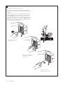
1
2
Screwdriver slot
Wire hole
Wire
This kit uses spring clamp style terminals.
Terminals use a steel spring to clamp the wire to provide
improved vibration resistance, reduced maintenance and faster
installation.
To connect wires, firmly insert a slotted screwdriver into the
square hole (
1 2
) to open the spring. When fully inserted, the
screwdriver will lock into place, allowing you to remove your
hand and insert the wire into the round hole (
1
2). Remove the
screwdriver to clamp the wire. The wire is held securely against
the bus bar for low contact resistance over time without the
need to periodically retighten screws.
• Push screwdriver FIRMLY
into square hole.
• Insert wire into round hole.
• Use green terminal for braid
and ground wire.
• Remove screwdriver.
• Repeat for all connections.
16
8 | nVent.com/RAYCHEM

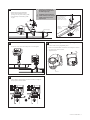
nVent recommends the use of a
conduit drain to prevent
water condensation build-up.
Make sure
conductors are
not exposed.
Conduit
drain
3/4 in locknut
Water tight
conduit seal
1/2 in
(13 mm)
Power and ground wires
Weather seal
• Install conduit and fittings as shown. To
minimize loosening due to pipe vibration,
use flexible conduit.
• Pull in power and ground wires, strip off
• Plug in the light module in the
terminal blocks marked L and
N
as shown.
(For simplicity the connected
wires in the terminal blocks are
not shown in this step.)
• Install lid.
• Apply insulation and cladding.
• Weather-seal the stand entry.
• Leave these instructions
with the end user for
future reference.
17
18 19
WARNING: Explosion Hazard- Substitution of Components May Impair
Suitablity for Class I Division 2 (Zone 2)
WARNING: Explosion Harzard- Do Not Disconnect Equipment Unless Power has
been Switched Off or The Area is Known to be Non-Hazardous.
AVERTISSEMENT: Risque d’explosion. La substitution de composants peut
rendre ce matériel inacceptable pour les emplacements de classe I, Division 2
(Zone 2).
AVERTISSEMENT: Risque d’explosion. Ne pas débrancher l’appareil à moins
d’avoir coupé l’alimentation électrique ou à moins qu’il ne s’agisse d’un
emplacement non dangereux
nVent.com/RAYCHEM
|
9


© nVent. All nVent marks and logos are owned or licensed by nVent Services GmbH or its affiliates. All other trademarks are the property of their respective owners.
nVent reserves the right to change specifications without notice.
nVent.com/RAYCHEM
North America
Tel +1.800.545.6258
Fax +1.800.527.5703
Europe, Middle East, Africa
Tel +32.16.213.511
Fax +32.16.213.604
Asia Pacific
Tel +86.21.2412.1688
Fax +86.21.5426.3167
Latin America
Tel +1.713.868.4800
Fax +1.713.868.2333
-
 1
1
-
 2
2
-
 3
3
-
 4
4
-
 5
5
-
 6
6
-
 7
7
-
 8
8
-
 9
9
-
 10
10
-
 11
11
-
 12
12


nVent RAYCHEM H59057 Single Entry Power Connection Manuel utilisateur
- Taper
- Manuel utilisateur
dans d''autres langues
Documents connexes
-
 nVent RAYCHEM JBS-100-STB Single Entry Power Connection Manuel utilisateur
-
 nVent RAYCHEM JBM-100-L-A Multi Entry Connection Kit Manuel utilisateur
-
 nVent RAYCHEM E-100-A High-Profile End Seal Kit Manuel utilisateur
-
 nVent RAYCHEM JBM-100-A Multiple-Entry Power-Tee Connection Manuel utilisateur
-
nVent RAYCHEM E-100-L-E Mode d'emploi


