Magnetrol Echotel 961/962 Line Powered Mode d'emploi
- Taper
- Mode d'emploi

Ultrasonic
Single and
Dual Point
Level Switches
Installation and Operating Manual
ECHOTEL
®
961/962
LINE POWERED
Model 961
Model 962

2
UNPACKING
U
npack the instrument carefully. Make sure all components
have been removed from the foam protection. Inspect all
components for damage. Report any concealed damage to
the carrier within 24 hours. Check the contents of the car-
ton/crates against the packing slip and report any discrep-
ancies to Magnetrol. Check the nameplate model number
to be sure it agrees with the packing slip and purchase
order. Check and record the serial number for future refer-
ence when ordering parts.
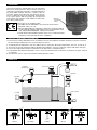
MOUNTING
N
ameplate:
- part number
- serial n°
Varivent
®
These units are in compliance with:
1.The EMC directive 2014/30/EU. The units have been tested to
EN 61326: 1997 + A1 + A2.
2.Directive 2014/34/EU for equipment or protective system intended for
use in potentially explosive atmospheres. EC-type examination certifi-
cate number FM19ATEX0204X - flameproof enclosure.
3.RoHS directive 2011/65/EU (restriction of the use of certain hazardous
substances in electrical and electronic equipment).
H
igh alarm
H
igh high alarm
High alarm
High alarm
Pump control
Auto fill or
empty pump control
Filling line
Pump protection
Pump
Low alarm
Tri-Clamp
®
DIN 11851Threaded Welded flange
SPECIAL CONDITIONS FOR ATEX USE
1.The enclosure contains aluminum and is considered to present a potential risk of ignition by impact or friction. Care must
be taken during installation and use to prevent impact or friction.
2. To maintain the T6 temperature code care shall be taken to ensure the “Enclosure Temperature” does not exceed 70 °C.
3. The risk of electrostatic discharge shall be minimized at installation, clean non-conductive surfaces with moist cloth only.
4. Contact the original manufacturer for information in the dimensions of flameproof joints.
5.For installation with ambient temperature of 70 °C, refer to the manufacturer’s instructions for guidance on proper selection
of conductors.
6. The ultrasonic probe is only for use with the Echotel ultrasonic switch.

3
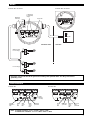
WIRING
Echotel
®
961 electronics Echotel
®
962 electronics
TIME
D
ELAY
LEVEL
TEST
MALF
TEST
M
ALF RELAY
FAULT
MALF
LOWER
UPPER
MODEL 962
N
C C NO
N
C C NO NC C NO L2L1
Hi PC
L
o LC
L
OWER
U
PPER
Important: Connect the unit to the ground for avoiding earth potential drifts. Use the green internal
grounding screw
Note: in normal operation «Fault» is OFF / «MALF» is ON
in malfunction condition: «Fault» is ON / «MALF» is OFF
T
IME
D
ELAY
L
EVEL
T
EST
M
ALF
TEST
M
ALF RELAY
FAULT
WET
LEVEL
MALF
MODEL 961
L1
L2
+
-
NC C NONC C NO NC C NO L2L1
Hi I
Lo J
Malfunction
SPDT relay
Malfunction relay
P
rocess relay(s)
1
00 to 265 V AC
12 to 35 V DC
NC
C
N
O
NC
C
NO
N
C
C
NO
Process relay(s)
Input power
1 x DPDT (961)
2 x SPDT (962)
r
elay(s)
Ground
H
AZARDOUS AREA
SAFE AREA
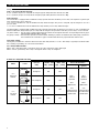
USER INTERFACE
Testing
malfunction
relay
Fault
red
LED
Wet
yellow
LED
Alarm
status
yellow
LED
Malfunction
green LED
Echotel
®
961 Echotel
®
962
TIME
DELAY
LEVEL
TEST
MALF
TEST
MALF RELAY
FAULT
WET
LEVEL
MALF
MODEL 961
NC C NONC C NO NC C NO L2L1
Hi I
Lo J
TIME
DELAY
LEVEL
TEST
MALF
TEST
MALF RELAY
FAULT
MALF
LOWER
UPPER
MODEL 962
NC C NONC C NO NC C NO L2L1
Hi PC
Lo LC
LOWER UPPER
Fault
red
LED
Malfunction
green LED
Lower gap
alarm
yellow
LED
Upper gap
alarm
yellow LED
Testing
DPDT pro-
cess relay

4
SET UP AND FUNCTIONS
Set up
High – Low Level Failsafe selection:
In
«
Hi
»
position, the process relay will de-energize (report alarm) when the transducer is wet.
In «Lo» position, the process relay will de-energize (report alarm) when the transducer is dry.
Fault selection:
The echotel 961 is equipped with a malfunction relay separate from the 5A DPDT process relay. The separate or joined oper-
ation of both relays can be selected :
I = in case of a malfunction, only the malfunction relay will de-energize. The process relay will only de-energize in case of a
p
rocess alarm
J = in case of a malfunction, both the malfunction relay and the process relay will de-energize
The Echotel 962 is equipped with a malfunction relay separate from the two 5A SPDT process relays. In case of a malfunction,
both the malfunction relay and the process relays will de-energize. The operation of the two process relays can be selected:
LC (level control) = the two relays operate independent and will be de-energized when the corresponding tranducer gap is
immerged/dry (following Hi/Lo setting)
PC (pump control) = the two relays operate in a latched mode, allowing to perform an automatic fill or drain pump control func-
tion in between the 2 transducer gaps. Consult below tables for proper indication and function.
Time delay setting:
Turning the potentiometer clockwise will increase the time delay from 0,5 s to 10 s. Time delay is typically used where turbu-
lence, boiling or splashing can cause false level alarms.
961 - Relay/ LED Indication:
When «WET» (wet LED): OFF = transducer gap is dry / ON = transducer gap is immerged
When «LEVEL» (level LED): ON = relay is energized / OFF = relay de-energized
Echotel 961: Relay/LED indication
Mode Level
Process
relay
« LEVEL» LED
(relay - yellow)
« WET» LED
(gap - yellow)
Error LED indication
Fault (red)
Malfunction
(green)
«Hi»
High level
failsafe
Energized ON OFF
OFF =
Normal
operation
ON =
Malfunction
See
troubleshooting
for malfunction
identification
ON =
Normal
operation
OFF =
Malfunction
See
troubleshooting
for malfunction
identification
De-energized OFF ON
«Lo»
Low level
failsafe
Energized ON ON
De-energized OFF OFF

5
SET UP AND FUNCTIONS
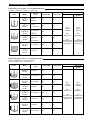
Echotel 962 as level control «LC»: Relay/LED indication
Level Mode
Process
relay
Lower LED Upper LED
Error LED indication
Fault (red)
Malfunction
(green)
«
Hi»
High level
failsafe
# 1 & 2:
Energized
ON ON
O
FF =
Normal
operation
ON =
Malfunction
See
troubleshooting
for malfunction
identification
O
N =
Normal
operation
OFF =
Malfunction
See
troubleshooting
for malfunction
identification
«Lo»
Low level
failsafe
#
1 & 2:
De-energized
OFF OFF
«Hi»
High level
failsafe
# 1:
De-energized
# 2:
E
nergized
OFF ON
«
Lo»
Low level
failsafe
# 1:
Energized
# 2:
De-energized
ON OFF
«Hi»
High level
failsafe
De-energized OFF OFF
«Lo»
Low level
failsafe
Energized ON ON
Relay # 1 = lower gap – Relay # 2 = upper gap
Echotel 962 pump control «PC»: Relay/LED indication
Level Mode
Process
relay
Lower LED Upper LED
Error LED indication
Fault (red)
Malfunction
(green)
«Hi»
High level
failsafe
Energized ON ON
OFF =
Normal
operation
ON =
Malfunction
See
troubleshooting
for malfunction
identification
ON =
Normal
operation
OFF =
Malfunction
See
troubleshooting
for malfunction
identification
«Lo»
Low level
failsafe
De-energized OFF OFF
«Hi»
High level
failsafe
De-energized OFF OFF
«Lo»
Low level
failsafe
Energized ON ON
«Hi»
High level
failsafe
De-energized OFF OFF
«Lo»
Low level
failsafe
Energized ON ON
«Hi»
High level
failsafe
Energized ON ON
«Lo»
Low level
failsafe
De-energized OFF OFF
High Level Failsafe (Hi) = auto empty mode
Low Level Failsafe (Lo) = auto fill mode

6
MAINTENANCE
Manual Testing
Level Test: (process relay(s)):
Pressing the “Level Test” pushbutton, will manually test the process relays and connected actuators/indicators. The level test
forces the relay(s) to change from a de-energized to an energized status and vice versa. The LED’s will be ON/OFF corre-
sponding (see tables in the configuration section). The time delay setting is not active during testing.
Malfunction Test (malfunction relay):
Pressing the “Malfunction Test” pushbutton for min 2 s, will manually test the malfunction relay and connected actuators/indi-
cators. The malfunction test simulates a circuit failure and forces all relays to de-energize. The «MALF» LED will turn OFF and
t
he «FAULT» LED ON. The time delay setting is not active during testing.
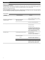
Troubleshooting
Problem Action/Indication Solution
No output signal No LED’s are ON
Check wiring / input power
Check for malfunction (962). See below
No change in output between
wet gap / dry gap
Gap may be plugged by
solids / dense foam
Clean the transducer
Gap is out of reach of liquid Check mounting section and relocate
the unit or check blocking valves.
Chattering output Excessive aeration / Turbulence Introduce a time delay
Check input power
Relocate the switch
If installed horizontally, make sure the
961 transducer gap is oriented in a ver-
tical position as shown in the mounting
section. This allows proper drainage
from the gap, and prevents air bubbles
from accumulating in the gap.
Fault LED is ON A system fault has been detected Check input power
Check wiring between transducer and
electronics or replace transducer.
Press «LEVEL TEST» test pushbutton
to identify the problem:
* --- * : 1 flash
Check wiring between transducer and
electronics or replace transducer.
** --- ** : 2 flashes Replace electronics
*** --- *** : 3 flashes The unit senses excessive noise
interference. Check shield connection or
eliminate interference from a walkie-
talkie, radio or other nearby source

7
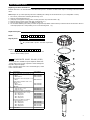
REPLACEMENT PARTS
Replacing electronics/transducer
Replacement parts
E
chotel electronics can be removed in the field under process conditions. Follow below steps to exchange electronics/trans-
ducer:
Note: Adjust set up of the replacing electronics following the settings of the old electronics (see configuration section)
1. Disconnect power before removing the housing cover
2. Remove power/output wires (a)
3. (Skip step 3 if hygienic housing.) Click out the protection cap of the electronics (b)
4. Remove the 2 bracket screws and slide out electronics (c)
5
. Remove the transducer wires (see Wiring section) (d)
6. Re-assemble following the same procedure in opposite way. Make sure that the tip on the bracket of the electronic block is
seated properly in the corresponding recess in the housing base - (e)
No. Description Part Number
1 Cast aluminium cover
(digit 10 = 0 or 1)
Blind
With window
Cast stainless steel cover
(digit 10 = 2 or 3)
Blind
Deep drawn stainless steel cover
(digit 10 = 4 or 5)
Blind
With window
004-9192-009
036-4410-010
004-9224-014
032-3934-001
036-5702-002
2 “O”-Ring
digit 10 = 0, 1, 2 or 3
digit 10 = 4 or 5
012-2201-237
012-2201-155
3 Electronic module for industrial
housing
(
digit 10 = 0, 1, 2 or 3
)
961 – AC power
961 – DC power
962 – AC power
962 – DC power
Electronic module for hygienic
housing (digit 10 = 4 or 5)
961 – AC power
961 – DC power
962 – AC power
962 – DC power
089-7259-001
089-7259-002
089-7258-001
089-7258-002
089-7256-001
089-7256-002
089-7257-001
089-7257-002
4 Transducer consult factory
1
3
3
3
3
2
4
a
d
e
b
c
1X
74
2 3 8 9 105 6
Digit in partn°:
Partn°:
Serial n°:
X = product with a specific customer requirement
See nameplate, always provide complete partn° and
serial n° when ordering spares.
E X P E D I T E S H I P P L A N ( E S P )
Several parts are available for quick shipment, within max.
1 week after factory receipt of purchase order, through the
Expedite Ship Plan (ESP).
Parts covered by ESP service are conveniently grey coded
in the selection tables.

8
2. Code for Echotel
®
transducer
MODEL IDENTIFICATION
A complete measuring system consists of:
1. Echotel
®
electronics
2. Echotel
®
transducer
1. Code for Echotel
®
electronics
9 D A6 0
complete code for Echotel
®
electronics
0 Integral mount electronics
1 2 3 | BASIC MODEL NUMBER
961 Echotel 961 electronics for single setpoint 9M1 transducers
962 Echotel 962 electronics for dual setpoint 9M2 transducers
4
5 6 | INPUT POWER
8 | MOUNTING
0 Blind housing cover
1 Housing cover with glass window (not for cast stainless steel housings)
7 | ACCESSORIES
C
ATEX II 1/2 G / IEC Ex db IIC T6 Ga/Gb, flameproof enclosure
-
except deep drawn SST housing
3 Weatherproof -
except deep drawn SST housing
7 Weatherproof -
deep drawn SST housing
9 | APPROVALS
1 Cast aluminium housing with M20 x 1,5 cable entry (2 entries – one plugged)
0 Cast aluminium housing with 3/4" NPT cable entry (2 entries – one plugged)
3 Cast stainless steel with M20 x 1,5 cable entry (2 entries – one plugged)
2 Cast stainless steel with 3/4" NPT cable entry (2 entries – one plugged)
5
Deep drawn 304 stainless steel with M20 x 1,5 cable entry (2 entries – one plugged)
4
Deep drawn 304 stainless steel with 1/2" NPT cable entry (1 entry)
10 | HOUSING / CABLE ENTRY
2
DA 12 - 35 V DC line powered electronics with 5 A gold flash relay(s) output
7D A 100 - 265 V AC line powered electronics with 5 A gold flash relay(s) output
X = product with a specific customer requirement
complete code for Echotel
®
transducer
A 316/316L (1.4401/1.4404) stainless steel
B Hastelloy
®
C (2.4819) – only available with 9M1
C Monel
®
(2.4360) – only available with 9M1
N 316/316L (1.4401/1.4404) stainless steel & NACE MR0175/MR0103
P CPVC
R Kynar
®
(PVDF) – only available with 9M1
S 316/316L (1.4401/1.4404) stainless steel with 0,5 µm Ra (20 Ra) surface finish
1 2 3 | BASIC MODEL NUMBER
9M1 Echotel
®
961 transducer with single setpoint
9M2 Echotel
®
962 transducer with dual setpoints
4 | TRANSDUCER MATERIALS (use only metal transducers for hazardous area)
9 M
X = product with a specific customer requirement
SEE NEXT PAGE
1 75 642 3 8 9 10
1
7
5 6
4
2 3 8 9 10

9
MODEL IDENTIFICATION
9 M
complete code for Echotel
®
transducer
8 9 10 | ACTUATION LENGTH – specify per cm (0.39") increment
Total insertion length = actuation length + 6 mm (0.25")
9M1 transducers
003 Minimum 3 cm (1.2") – for metal transducers with NPT connections only
005 Minimum 5 cm (2") – for all other connections
304 Maximum 304 cm (120") – for Kynar
®
(PVDF) material
330 Maximum 330 cm (130") – for all other materials
9M2 transducers "A" length
specify "B" length separately
(see drawing and note shown in the dimensions section)
013 Minimum 13 cm (5.1") – for metal transducers with NPT connections only
015 Mininimum 15 cm (5.9") – for all other connections
330 Maximum 330 cm (130")
A
Standard sensor: min -40 °C / max +165 °C (-40 °F / +325 °F)
C
Low temperature sensor: min -80 °C / max +120 °C (-110 °F / +250 °F) – only
available with 9M1-A
7 | SENSOR TYPE
X = product with a specific customer requirement
5 6 | PROCESS CONNECTION
Threaded (plastic transducers are only available with 3/4" NPT connection)
23 1" 150 lbs ASME RF
¡
33 1 1/2" 150 lbs ASME RF
¡
43 2" 150 lbs ASME RF
¡
ASME Flanges for plastic transducers
¿
BA
DN 25 PN 16 EN 1092-1 Type A
CA
DN 40 PN 16 EN 1092-1 Type A
DA
DN 50 PN 16 EN 1092-1 Type A
EN Flanges for plastic transducers
¿
3T 1 1/2" Tri-clamp
®
4T 2" Tri-clamp
®
VV DN 65 Varivent
®
type N
Hygienic
BS DN 25 DIN 11851
CS DN 40 DIN 11851
DS DN 50 DIN 11851
¿ CPVC flanges for CPVC transducers, Kynar
®
cladded SST flanges for Kynar
®
transducers
¡ FF (flat face) flanges for CPVC transducers
11 3/4" NPT
21 1" NPT
12 3/4" BSP (G 3/4")
22 1" BSP (G 1")
23 1" 150 lbs ASME RF
24 1" 300 lbs ASME RF
25 1" 600 lbs ASME RF
33 1 1/2" 150 lbs ASME RF
34 1 1/2" 300 lbs ASME RF
35 1 1/2" 600 lbs ASME RF
4
3 2" 150 lbs ASME RF
44 2" 300 lbs ASME RF
45 2" 600 lbs ASME RF
53 3" 150 lbs ASME RF
54 3" 300 lbs ASME RF
55 3" 600 lbs ASME RF
63 4" 150 lbs ASME RF
64 4" 300 lbs ASME RF
65 4" 600 lbs ASME RF
ASME Flanges for metal transducers
BB DN 25
PN 16/25/40
EN 1092-1 Type A
BC DN 25 PN 63/100 EN 1092-1 Type B2
C
B DN 40
P
N 16/25/40
E
N 1092-1 Type A
CC DN 40 PN 63/100 EN 1092-1 Type B2
DA DN 50 PN 16 EN 1092-1 Type A
D
B DN 50 PN 25/40 EN 1092-1 Type A
DD DN 50 PN 63 EN 1092-1 Type B2
DE DN 50 PN 100 EN 1092-1 Type B2
EA DN 80 PN 16 EN 1092-1 Type A
EB DN 80 PN 25/40 EN 1092-1 Type A
ED DN 80 PN 63 EN 1092-1 Type B2
EE DN 80 PN 100 EN 1092-1 Type B2
FA DN 100 PN 16 EN 1092-1 Type A
FB DN 100 PN 25/40 EN 1092-1 Type A
FD DN 100 PN 63 EN 1092-1 Type B2
FE DN 100 PN 100 EN 1092-1 Type B2
EN Flanges for metal transducers
SEE PREVIOUS PAGE
2. Code for Echotel
®
transducer
1
7
5
64
2 3 8 9 10

10
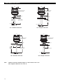
DIMENSIONS IN mm (inches)
1
02
(4)
6
(0.25)
46 (1.8) Typical
Ø
22,9 (0.90)
A
ctuation length
for NPT connection
Actuation
length
f
or BSP
connection
113 (4.43) without window
1
23 (4.85) with window
102
(4)
6 (0.25)
60 (2.35) Typical
Ø
22,9 (0.90)
Actuation length
113 (4.43) without window
123 (4.85) with window
961 - Threaded connection
961 - Flanged connection
1
02
(4)
6 (0.25)
46 (1.8) Typical
Ø 22,9 (0.90)
Actuation length “A”
for NPT connection
Actuation length “B”
for NPT connection
A
ctuation
length “A”
for BSP
connection
Actuation length
“B” for BSP
c
onnection
1
13 (4.43) without window
123 (4.85) with window
102
(4)
6 (0.25)
60 (2.35) Typical
Ø 22,9 (0.90)
Actuation length “A”
A
ctuation length
“B”
113 (4.43) without window
123 (4.85) with window
962 - Threaded connection 962 - Flanged connection
Note: - Difference between actuation lengths "A" and "B" must be min. 8 cm.
- Max. length for dimension "B" is 322 cm.

11
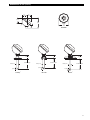
DIMENSIONS IN mm (inches)
Cable entry
60
(2.36)
125
(
4.92)
43°
52
(2.05)
58
(
2.28)
1
09
(4.28)
43° View
29 (1.14)
Ø
22,9 (0.90)
A
ctuation Length
Tri-Clamp
®
35 (1.38)
Ø
22,9 (0.90)
Actuation Length
DIN 11851
46 (1.81)
Ø 22,9 (0.90)
6 (0.25)
6 (0.25)
6 (0.25)
Actuation Length
Varivent
®

12
SPECIFICATIONS
Description Specification
Input Voltage 100 - 265 V AC 50/60 Hz or 12 - 35 V DC
Power Consumption < 3 Watt
Output
961: one 5 A DPDT relay,
962: two 5 A SPDT relays
961/962: one 5 A SPDT malfunction relay
Time delay 0,5 to 10 s adjustable (in addition to transducer response time)
Indication
LED’s for process alarm status, malfunction (error of transducer, electronics or elec-
trical noise interference) and wet/dry status of transducer (961 only)
Selftest
Automatic Continuously verifies electronics, transducer and noise interference
Manual Via pushbutton for checking alarm output(s) and error output/function.
Housing material IP66, cast aluminium, cast stainless steel or deep drawn 304 stainless steel (IP 67)
Approvals
¿
ATEX II 1/2 G Ex db IIC T6 Ga/Gb flameproof enclosure
IEC Ex db IIC T6 Ga/Gb
Overfill prevention TÜV - WHG § 63 / VLAREM II 5.17.7
Other approvals are available, consult factory for more details
SIL (Safety Integrity Level)
Functional safety to SIL 2 in accordance to IEC 61508 – SFF > 90 %.
Full FMEDA report and declaration sheets available at request.
Shock/Vibration ANSI/ISA-S71.03 Class SA1 (shock), ANSI/ISA-S71.03 Class VC2 (vibration)
Net weight
Aluminium / Deep drawn 304 SST: 1 kg (2.2 lbs) – electronics only
Cast SST: 2,5 kg (5.5 lbs) – electronics only
Description Specification
Response time 0,5 s typical
Repeatability ± 2 mm (0.078")
Ambient Temperature -40 °C to +70 °C (-40 °F to +160 °F)
Humidity 0-99 %, non-condensing
Electromagnetic Compatibility Meets CE requirements (EN 61326: 1997 + A1 + A2) and NAMUR NE 21
Electronics specifications
Performance
Transducer specification
¿
Only available with cast aluminium or cast stainless steel housings.
Description Plastic transducers Metal transducers
Material
CPVC
Kynar
®
(PVDF)
316/316L SST (1.4401/1.4404)
Hastelloy
®
C (2.4819)
Monel
®
(2.4360)
Mounting Threaded (NPT/BSP) – Flanged (ASME - EN) – Hygienic
Actuation length
From 5 cm up to 304 cm
(2" up to 120") – PVDF
From 5 cm up to 330 cm
(2" up to 130") – CPVC
From 3 cm up to 330 cm (1.2" up to 130")
Process temp. (consult temp/
press. graphs)
-40 °C to +120 °C (-40 °F to +250 °F) – PVDF
-40 °C to +80 °C (-40 °F to +180 °F) – CPVC
-40 °C to +165 °C (-40 °F to +325 °F) – standard
-80 °C to +120 °C (-110 °F to +250 °F) – low
temperature version in 316/316L SST
Max pressure (consult temp/
press. graphs)
13,8 bar @ +40 °C (200 psi @ +100 °F)
for NPT threaded units
82,8 bar (1200 psi) for Monel transducers
Consult temp/press. graphs for other
materials
Flanged models are downrated to the design pressure of the selected flange

13
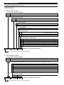
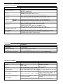
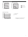
PRESSURE / TEMPERATURE RATINGS
R
ange with 3/4" NPT
R
ange with 150# flange
Range with PN16 flange
Process temperature (°C)
Process temperature (°C)
Process pressure (bar)
Process pressure (bar)
3
0
25
20
15
1
0
5
-40 0 40 80 120
0
Kynar
®
Transducer Ratings
Process temperature (°C)
Process pressure (bar)
3
0
25
2
0
15
10
5
-40 0 40 80 120
0
CPVC Transducer Ratings
Metal Transducer Ratings
¿
Only applicable to NPT-connections with actuation length = 3 cm
and BSP/ASME/EN-connections with actuation length = 5 cm
¡
For low temperature sensor: from -80 °C up to +120 °C
3
16/316L (1.4401/1.4404)
¡
Hastelloy
®
C (2.4819)
Monel
®
(2.4360)
0-40 40 80 120 165
4
0
80
120
160
1
38 bar
¿
103 bar
82,8 bar

14
Notes

15
Notes

IMPORTANT
SERVICE POLICY
Owners of Magnetrol products may request the return of a control; or, any part of a control for complete rebuilding or
replacement. They will be rebuilt or replaced promptly. Magnetrol International will repair or replace the control, at no cost to
t
he purchaser, (or owner) other than transportation cost if:
a. Returned within the warranty period; and,
b. The factory inspection finds the cause of the malfunction to be defective material or workmanship.
If the trouble is the result of conditions beyond our control; or, is NOT covered by the warranty, there will be charges for labour
and the parts required to rebuild or replace the equipment.
In some cases, it may be expedient to ship replacement parts; or, in extreme cases a complete new control, to replace the
original equipment before it is returned. If this is desired, notify the factory of both the model and serial numbers of the
control to be replaced. In such cases, credit for the materials returned, will be determined on the basis of the applicability of
our warranty.
No claims for misapplication, labour, direct or consequential damage will be allowed.
RETURNED MATERIAL PROCEDURE
So that we may efficiently process any materials that are returned, it is essential that a “Return Material Authorisation” (RMA)
form will be obtained from the factory. It is mandatory that this form will be attached to each material returned. This form is
available through Magnetrol’s local representative or by contacting the factory. Please supply the following information:
1. Purchaser Name
2. Description of Material
3. Serial Number and Ref Number
4. Desired Action
5. Reason for Return
6. Process details
Any unit that was used in a process must be properly cleaned in accordance with the proper health and safety standards
applicable by the owner, before it is returned to the factory.
A material Safety Data Sheet (MSDS) must be attached at the outside of the transport crate or box.
All shipments returned to the factory must be by prepaid transportation. Magnetrol will not accept collect shipments.
All replacements will be shipped Ex Works.
European Headquarters & Manufacturing Facility
Heikensstraat 6
9240 Zele, Belgium
Tel: +32-(0)52-45.11.11 • Fax: +32-(0)52-45.09.93
e-mail: [email protected]
www.magnetrol.com
BULLETIN N°: BE 51-645.12
EFFECTIVE: AUGUST 2020
SUPERSEDES: August 2017
UNDER RESERVE OF MODIFICATIONS
-
 1
1
-
 2
2
-
 3
3
-
 4
4
-
 5
5
-
 6
6
-
 7
7
-
 8
8
-
 9
9
-
 10
10
-
 11
11
-
 12
12
-
 13
13
-
 14
14
-
 15
15
-
 16
16


Magnetrol Echotel 961/962 Line Powered Mode d'emploi
- Taper
- Mode d'emploi
dans d''autres langues
Documents connexes
Autres documents
-
Toro Replacement Bag Kit, 37" Bagger Guide d'installation
-
Eurotherm P304 Guide d'installation
-
-
MKS T3PIA Manuel utilisateur
-
Raypak XVers L 406L-856L Type H Mode d'emploi
-
WIKA CPT-20 tag:model:CPT-21 Mode d'emploi
-
ClimateMaster Dedicated Outside Air Systems Le manuel du propriétaire