NewAge Products 54233 Manuel utilisateur

Taper
Manuel utilisateur
Pro Series
2x4ft Wall Mounted Shelf
Warning: Excessive weight hazard!
Use two or more people to move, assemble or install cabinets and locker to avoid back injury.
Do not leave children unattended near cabinets. High risk of tipping if cabinets are installed
incorrectly: securely attach cabinets to the wall to avoid serious injury.
For assistance, call 1.877.306.8930; for UK 0800.031.4069; e-mail at [email protected]
STOP
ATTENTION:
Is your Wall Mounted Shelf damaged?
Need help or spare parts?
For fastest service, contact NewAge Products at
1-877-306-8930; or suppor[email protected].
Do not return to the retailer.
Use two or more people to move, assemble, or install
Wall Mounted Shelf to avoid back or other injury. Do
not leave children unattended near Wall Mounted
Shelf. High risk of items falling if Wall Mounted
Shelf is installed incorrectly: must be securely
installed to avoid serious injury. For assistance, call
1.877.306.8930; e-mail at info@newageproducts.
com.
Warning: Excessive weight
hazard!
2
INDEX
Product Overview:
Safety Warning - 3
Tools Needed - 5
Included Quantities - 6
Spare Parts - 7
Weight Capacity - 8
Installation Overview - 9
Installation Overview:
Installation Options - 10
Wall Conguration: Installation Location - 11
Ceiling Conguration: Installation Location - 12
Installing Wall Brackets & Back Beam - 13, 14
Wall Conguration: Installing Pad Eye Plate - 15
Perimeter Beam & Cable Assembly-16
Ceiling Conguration: Installing Pad Eye Plate - 17
Perimeter Beam & Cable Assembly - 18
Cable Assembly - 19
Cross Support Assembly - 21
Grid Supports & Wire Grids - 21, 22
Installation Tips
Irregular Joist Spacing - 23
Fastening to Engineered Joists - 25
Connecting Wall Mounted Shelf Horizontally - 26
Connecting Wall Mounted Shelf Vertically - 27
Connecting Corner Wall Mounted Shelf - 28,29
3
1. All Wall Mounted Shelf units have a rated load capacity of 600 pounds, evenly distributed,
using 3” lag bolts anchored into solid wood studs or 3” concrete anchors into solid concrete
supports capable of supporting such a load.
2. Each Wall Mounted Shelf utility hook can hold a maximum of 50lbs. Weight of utility hook
storage must be included in the maximum load of 600lbs for the overhead rack.
3. Do not load more than 600lbs onto a Wall Mounted Shelf. Live loads (people,pets, etc.)
may weigh less than the rated weight capacity, however will exert force on the rack beyond
its rated capacity. As such, do not stand, jump or hang from your Wall Mounted Shelf.
4. Wall Mounted Shelf units must be installed into structurally sound overhead/wall joists or
supports. NewAge Products Inc. make no claim to the capacity or strength of the structure
to which the units are mounted.
5. NewAge Products Inc. cannot be held liable for structure failure, or damage or injury
resulting from structural failure.
6. Always inspect the structure of the ceiling and wall to ensure there are suitable supports.
7. The Wall Mounted Shelf is designed for installation into wooden joists/studs and solid
concrete. Do not attempt mounting to steel beams.
8. Ensure all weight is distributed evenly on the rack. Place heavier objects near the
perimeter frame and cross supports with lighter objects in the center.
9. Do not jump or climb on your Wall Mounted Shelf.
10. Do not lean a ladder against the Wall Mounted Shelf.
11. Routinely inspect your system to ensure all components are fastened correctly
SAFETY WARNING
PLEASE READ THIS FIRST
4
Manufacturer Warranty Limited Lifetime
1. Service calls to correct the installation of any NewAge products or to instruct you how to use or install them.
2.
3.
4. Repairs or replacement when your product is used in other than normal, single-family household use, such as a commercial
environment, or handled in anyway inconsistent with the installation instructions included with the product.
5.
6. Surfaces damaged due to chemical interaction resulting in corrosion of paint or metal.
7. Replacement parts for NewAge products outside Canada and the United States.
8.
9. Shipping or freight fees to deliver replacement products or to return defective products.
10. Any labor costs during the limited warranty period.
When this product is installed, operated and maintained according to the instructions attached to or furnished with the product,
NewAge Products Inc. will replace the defective product or parts if the part fails as a result of defective materials or workmanship
for the Lifetime of the product.
NEWAGE PRODUCTS INC. WILL NOT PAY FOR:
IMPLIED WARRANTIES, INCLUDING TO THE EXTENT APPLICABLE WARRANTIES OF MERCHANTABILITY OR FITNESS FOR A PARTICULAR
PURPOSE, ARE EXCLUDED TO THE EXTENT LEGALLY PERMISSIBLE. ANY IMPLIED WARRANTIES THAT MAY BE IMPOSED BY LAW ARE LIMITED
TO ONE YEAR, OR THE SHORTEST PERIOD ALLOWED BY LAW. SOME STATES AND PROVINCES DO NOT ALLOW LIMITATIONS OR EXCLUSIONS
ON HOW LONG AN IMPLIED WARRANTY OF MERCHANTABILITY OR FITNESS LASTS, SO THE ABOVE LIMITATIONS OR EXCLUSIONS MAY NOT
APPLY TO YOU. THIS WARRANTY GIVES YOU SPECIFIC LEGAL RIGHTS, AND YOU MAY ALSO HAVE OTHER RIGHTS WHICH VARY FROM STATE
TO STATE OR PROVINCE TO PROVINCE
DISCLAIMER OF IMPLIED WARRANTIES; LIMITATION OF REMEDIES
Damage resulting from improper handling, or products damaged by accident, misuse, abuse, re, ood, improper installation,
acts of God, neglect, corrosion, modication or mishandling.
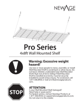
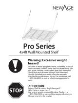
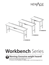
Products damaged by improperly loading beyond the specied maximum weight capacity outlined in the instructions provided
with the product.
Cosmetic damage, including scratches, dings, dents or cracks in paint that do not aect the structural or functional capability of
the product.
Loss of product contents due to theft, re, ood, accident or acts of God.
5
Unpacking
Begin by placing the package on a covered at surface.
Remove all cardboard, packaging material and clear plastic bags.
Dispose / recycle all packaging materials.
Verify all the contents in the box and gather the required tools. See Tools Needed , and
“Included Quantities” list.
Tools Needed
Magnetic Leveler
Tape Measure
7/16” & 1/2”
socket
Cordless Power Drill
Stud Finder
Pencil
7/16” & 1/2”
Socket Wrench
Ladder
Rubber Mallet
Safety Glasses
3/16” Drill Bit
1 x Hammer Drill
1 x
Masonry Bit
[optional for masonry]
6
Included Quantities
2x4ft Pro Series Wall Mounted Shelf
Part Number DESCRIPTION QTY.
WSH-03A-01-XX 2x4ft Pro Series Wall Mounted Shelf 1
WSH-02.002A-01-XX 2ft Side Beam - RHS 1
WSH-01.005A-01-XX Back Beam 1
WSH-02.001A-01-XX 2ft Side Beam - LHS 1
WSH-03.001A-01-XX 4ft Front 'c' channel 1
WSH-02.006A-01-XX 2ft Cross Support 2
H00004A-01 1/4-20x0.75in Hex Bolt 9
H00005A-01 1/4-20 Lock Nut 9
H00002A-01 1/4in Flat Washer 20
WSH-02.003A-01-XX 2ft Finishing Grid Sections 2
WSH-02.005A-01-XX 2ft 'U' Shaped Grid Supports 3
WSH-02.004A-01-XX 2ft Middle Grid Sections 2
WSH-01.006A-01-XX Back Hanging
Bracket 2
H00001A-01 1/4-20x0.625in Carriage Bolt 2
H00003A-01 1/4-20 Acorn Nut 2
QTY.
H00009A-01 1/4 x 3in Lag Screw 6
WSH-02.007A-01 2ft Wire Cable Assembly 2
WSH-02.007.01A-01
2ft Wire Cable
2
WSH-01.014.02A-01 Aluminium Sleeve 4
WSH-01.014.07A-01 Quick Link Connector 2
WSH-01.014.08A-01
Quick Link Connector - Closing/
Opening Cylinder
2
WSH-01.014.03A-01 Capel 4
WSH-01.012A-01-XX Pulley Cable Cap 2
WSH-01.013A-01 Pulley 2
H00006A-01 5/16-18x1.25in Hex Bolt 4
H00007A-01 5/16-18 Lock Nut 4
H00008A-01 5/16in Flat Washer 2
WSH-01.015A-01 Pad Eye Plate 2
H00010A-01 Concrete Anchors 6
Part Number DESCRIPTION
1
2
3
4
5
6
7
8
9
10
11
12
13
14
15
16
17
18
19
20
21
22
23
22
15
15
19
18
17
20
21
9
1
12
2
5
4
6
6
6
7
7
14
13
7
8
8
8
8
8
8
3
11
16
10
7
Spare Parts
Pulley Cable Cap
Pulley
Lag Screw (1/4” dia x 3”) Concrete Anchor
(M6 x 3”)
Hex Bolt
(5/16” dia x 1.25”)
(1/4” dia x 0.75”)
Carriage Bolt
(1/4” dia x 3/4”)
Lock Nut
(5/16”)
(1/4”)
Acorn Nut
(1/4”)
Flat Washer
(1/4”)
Flat Washer
(5/16”)
SKU 40481
Part # : WSH-02.007A-01
Cable Assembly
SKU 40482
Part # : WSH-01.015A-01
Pad Eye Plates
SKU 40483
Hardware Box
SKU 40484
Part # : WSH-01.006A-01-BS
Black - Back Hanging Brackets
SKU 40485
Part # : WSH-01.006A-01-WH
White- Back Hanging Brackets
2ft Cable Assembly
4mm cable
Aluminium Sleeve
Capel
Quick Link Connector
1/4-20 x 0.625in Carriage Bolt
1/4in Flat Washer
1/4-20 Acorn Nut
1/4-20 x 0.75in Hex Bolt
1/4-20 Lock Nut
5/16-18x1.25in Hex Bolt
5/16-18 Lock Nut
5/16in Flat Washer
1/4 x3in Lag Screw
Concrete Anchors
Pulley
Pulley Cable Cap
8
Safety Warning: All Wall Mounted Shelf units have a rated load capacity of 600 pounds,
evenly distributed, using 3” Lag Screws anchored into solid wood studs or concrete
supports capable of supporting such a load.
Ensure all weight is distributed evenly on the rack. Place heavier objects near the
perimeter frame and cross supports with lighter objects in the center.
Weight Capacity
600lbs.
450lbs. 450lbs.
300lbs.
300lbs.
400lbs. 400lbs. 400lbs.
300lbs.
300lbs.
300lbs.
300lbs.
Single Wall Mounted Shelf
Two Linked Wall
Mounted Shelves
Installed Vertically
Two Linked Wall Mounted Shelves Installed Horizontally
Three Linked Wall Mounted Shelves Installed Horizontally
Four Linked Wall Mounted Shelves Installed Vertically & Horizontally
9
Wall Mounted Shelf Installation Overview
Install the Pad Eye Plate and Side Beams
with Cable Assemblies. (Page 15-19)
Install wall brackets & back perimeter
beams onto the wall at a determined
height. (Page 13-14)
Determine your preferred conguration
before beginning assembly. (Page 10)
Plan your Wall Mounted Shelf
installation location, determine
orientation and verify spacing of studs.
(Page 11-12)
Wall brackets must be fully
secured to studs using 1 lag bolt
each or to concrete wall using 1
concrete anchor.
Read through the entire
instruction manual rst before
beginning installation.
Install the front perimeter beams and
angled cross supports. (Page 20-21)
Place the grid supports followed by the
steel grids to complete the Wall Mounted
Shelf installation. (Page 21-22)
1
2
3
5
6
4
Note:
If installing the Wall Mounted Shelf cables to the wall, start on page 11. If installing the Wall Mounted Shelf
cables to the ceiling, start on page 12.
10
Installation options for Wall Mounted Shelf
Connecting Wall Mounted Shelves
Horizontally. (Page 26)
Single Wall Mounted Shelf attached to
ceiling. Distance from Ceiling is adjustable
from 18in to 33in.
(Start on page 12, Option B)
Single Wall Mounted Shelf attached to wall.
(Start on page 11, Option A )
Important information: Please read
entire manual before beginning
installation.
Corner Wall Mounted Shelf
(Page 28)
Connecting Wall Mounted Shelves Vertically
(Page 27)
Option A.
Option B.
Option E.
Option C.
Option D.
Layouts shown are examples only.
Do not exceed total weight capacity of
Wall Mounted Shelf.
Plan layout and measure space for
clearance and stud spacing before
installing.
Ensure wall mounted shelf is securely
installed to suitable structure.
11
Ceiling Mounted Depth:
44”
Wall Mounted:
35”
Ceiling Mounted:
18-57”
Wall Mounted:
26”
Once it is determined that your Wall Mounted Shelf will be installed to the wall, verify
there is sucient clearance. Mark the desired position of the bottom of the Wall Mounted
Shelf with a horizontal level line across the wall.
Plan the Installation Location
Option A: Installing Wall Mounted Shelf To the Wall
Note:
Wall mounted congurations require
greater than 26” between the ceiling and
the bottom of the Wall Mounted Shelf.
Note:
Skip to page 13 to continue wall Installation.
Using a stud nder, locate and mark the center position of the studs on the wall. Check
the spacing of your wall studs and ensure they t the size of your install.
Maximum
Height: 57”
Minimum
Height: 18”
Level Line
48”
Maximum
Height: 57”
Minimum
Height: 18”
Level Line
2x4ft Wall Mounted Shelf
48”
Note:
If the spacing of your
studs do not align with
the install locations,
please refer to installing
a Wall Brace on page 25
Note:
Wall Mounting Brackets
should be placed 48in
apart center to center.
Installation options for Wall Mounted Shelf
Side View
1A
2A
12
Once it is determined that your Wall Mounted Shelf will be installed to the ceiling, verify
there is sucient clearance. Mark the desired position of the bottom of the Wall Mounted
Shelf with a horizontal level line across the wall.
Plan Installation Location
Option B: Installing Wall Mounted Shelf To the Ceiling
Note:
Ceiling mounted congurations can range
from 18-33” (Adjustable in 1” increments)
The center of the Pad Eye plates mounted
to the ceiling should be 22” from the back
wall.
Using a stud nder, locate and mark the studs on the wall. Check the spacing of your
ceiling joists and ensure they t the size of your install.
Note:
If the construction
of your ceiling is
using engineered
joists, please refer
to “Fastening to
Engineered Joists on
page 25.
If the spacing of your
studs do not align with
the install locations,
please refer to installing
a Wall Brace on page 25
Ceiling Mounted:
18-33” (Adjustable in
1” increments)
Ceiling Mounted
Depth: 22”
Ceiling Mounted Depth:
44”
Wall Mounted:
35”
Ceiling Mounted:
18-57”
Note:
Continue to page 13 for remaining ceiling installation.
Maximum
Height: 57”
Minimum
Height: 18”
Level Line
48”
1B
2B
Note:
Wall Mounting Brackets
should be placed 48in
apart center to center.
Maximum
Height: 57”
Minimum
Height: 18”
Level Line
2x4ft Wall Mounted Shelf
48”
13
Warning:
Make sure the Lag Screws
are tight against the stud
but DO NOT over-tighten
the lag screws.
If lag screws are over-
tightened, the lag screw
could snap or the hole
may be stripped.
Installing Wall Brackets & Back Beam
Masonry
Follow steps 1 to 11.
Drill pilot holes through the marked locations with hammer drill & 5/16” masonry bit.
Use Concrete Anchor for each pilot hole.
i
Align the bottom of the Wall Mounting
Bracket (#12) with the bottom level line
and the center of the wall stud with
the center of the horizontal slot in the
mounting bracket (mark the hole to be
drilled)
Drill a pilot hole using a 3/16” drill bit.
Note: Pilot hole must bore into 3 inches
of solid wood for lag screw to be fully
secured.
3
4
Insert one carriage bolt (#13) into the square opening that aligns with the wall stud.
Secure wall mounting bracket to stud using one 3in Lag Screw (#15), one 1/4” washer
(#8) and 7/16” socket. Note: If connecting 2 or more Wall Mounted Shelves horizontally,
refer to pg 26 before installing bracket.
5
i
14
6
iv
iv
iii
i
i
ii
iii
Mark next location for pilot hole using the wall mounting bracket (#12) and rear perimeter beam
(#2). Follow steps i through iii below.
Insert the Wall
Mounting Bracket and
Carriage Bolt onto the
Rear Perimeter Beam.
Mark the wall location to be drilled along the center of the stud (as shown above).
Mount the Rear
Perimeter Beam
onto the previously
installed Wall
Mounting Bracket.
Align the bracket with
the level line drawn
from step 2.
Note: Do not install nut onto carriage bolts until step 15.
Note: If the spacing of your studs do not align with the install locations refer to installing wall brace
on Page.25
ii
Drill a 3/16” pilot hole & secure wall mounting bracket into stud using one 3” Lag Screw (#15)
one 1/4” washer (#8) and a 7/16” socket. Ensure Carriage Bolt (#13) is mounted before installing
bracket.
Repeat steps 6 & 7 if connecting multiple wall mounted shelves horizontally.
7
8
Note:
To continue Wall Installation continue to page 15. To Continue Ceiling installation, skip to page 17.
15
Installing Pad Eye Plate
Option A: Wall Conguration
9A
10A 11A
Wall Mounted:
35”
Wall Mounted:
26”
Drill pilot holes into the solid wood using
a 3/16” drill bit.
Secure Pad Eye Plate (#22) to the
stud or joist using two 3” Lag Screws
(#15), and a 7/16” socket.
Wall Mounting: Measure and mark 26” vertically from the bottom of the Wall Mounted bracket
(#12) to the top of the pad eye plate (#22) . Align the pad eye plate on the center of the stud
and the top of the eye plate below the level line and mark the wall for pilot holes.
26”
Side View
Front View
#12
#22
Wood
Stud
Warning:
Must bore into
3 inches of solid
wood for lag screw
(#15) to be fully
secured.
Side View
16
Perimeter Beam & Cable Assembly
Option A: Wall Conguration
Wall Mounted Cable
Assembly:
Insert a 5/16” Hex Bolt into
the 33rd hole of the side
perimeter beam.
Attach cable eyelet to side beam (#1/#3) using 5/16” bolt (#19) , nut (#20) and fender washer (#21)
Insert a 5/16” Hex Bolt (#19) into the Front/First hole of the side perimeter beams. Slide Pully
cable cap (#17) onto the Hex Bolt and wrap the Cable Assembly around the pulley (#18). Slide
the Pulley Cable Cap onto the Hex Bolt and secure with a 5/16” lock nut (#20). Align tab on Pulley
Cable Cap with cutout in side frame.
Note:
To continue Wall Installation skip to page 19.
12A
13A
17
Installing Pad Eye Plate
Option B: Ceiling Conguration
Drill pilot holes into the solid wood
using a 3/16” drill bit.
Secure Pad Eye Plate (#22) to the
stud or joist using two 3” lag screws
(#15), and a 7/16” socket.
Note:
If Ceiling Joists are not in the
required location, refer to
“Installing with Irregular Joist
Spacing on Page 23.
9B
10B 11B
Ceiling Mounting: Measure and mark 22” from the wall, in line with the wall mounting bracket
(#12) and center of the ceiling joist, this will be the closest eye plate hole (#22) to the wall. Align
the pad eye plate on the center of the ceiling joist and mark the ceiling for pilot holes.
Side View
#12
#22
Wood
Stud
Warning:
Must bore into
3 inches of solid
wood for lag screw
(#15) to be fully
secured.
Side View
18
Perimeter Beam & Cable Assembly
Option B: Ceiling Conguration
Attach cable eyelet to side beam (#1/#3) using 5/16” bolt (#19), nut (#20) and fender washer (#21)
Insert a 5/16” Hex Bolt (#19) into the Front/First hole of the side perimeter beams. Slide Pully
cable cap (#17) onto the Hex Bolt and wrap the Cable Assembly around the pulley (#18). Slide
the Pulley Cable Cap onto the Hex Bolt and secure with a 5/16” lock nut (#20). Align tab on Pulley
Cable Cap with cutout in side frame.
Ceiling Mounted Cable
Assembly:
Attach the Cable Eyelet
(#16) to the respective hole
according to the distance
measured from the ceiling
to the bottom of the Wall
Mounted Shelf.
Example shown 18” from
ceiling = 18th hole.
Note:
To continue Ceiling installation continue to page 19.
12B
13B
19
Attach Side Beam( #1/#3) by guiding the mounting holes into the carriage bolt (#13) and
shoulder rivet on the wall bracket. Then bolt the side perimeter beam with a 1/4” washer (#8) and
1/4” acorn nut (#14).
Repeat steps 12-15 for the opposite side.
14
15
16
Attach the Quick Link Connector (#16) to
the Pad Eye Plate (#22).
(A) - Shoulder Rivet
Ceiling Mounted Wall Mounted
22
16
A
20
17
18
Guide the mounting holes of the front beam (#4) into the shoulder rivets on the side perimeter
beam. Use a rubber mallet to seat the rivets with the top of the keyholes.
Repeat step 16 for the opposite side of the beam
Interior View
Wall Mounted Ceiling Mounted
  • Page 1 1
  • Page 2 2
  • Page 3 3
  • Page 4 4
  • Page 5 5
  • Page 6 6
  • Page 7 7
  • Page 8 8
  • Page 9 9
  • Page 10 10
  • Page 11 11
  • Page 12 12
  • Page 13 13
  • Page 14 14
  • Page 15 15
  • Page 16 16
  • Page 17 17
  • Page 18 18
  • Page 19 19
  • Page 20 20
  • Page 21 21
  • Page 22 22
  • Page 23 23
  • Page 24 24
  • Page 25 25
  • Page 26 26
  • Page 27 27
  • Page 28 28
  • Page 29 29
  • Page 30 30
  • Page 31 31
  • Page 32 32
  • Page 33 33
  • Page 34 34
  • Page 35 35
  • Page 36 36
  • Page 37 37
  • Page 38 38
  • Page 39 39
  • Page 40 40
  • Page 41 41
  • Page 42 42
  • Page 43 43
  • Page 44 44
  • Page 45 45
  • Page 46 46
  • Page 47 47
  • Page 48 48
  • Page 49 49
  • Page 50 50
  • Page 51 51
  • Page 52 52
  • Page 53 53
  • Page 54 54
  • Page 55 55
  • Page 56 56
  • Page 57 57
  • Page 58 58

NewAge Products 54233 Manuel utilisateur

Taper
Manuel utilisateur

dans d''autres langues