Emerson Wireless 781S Smart Antenna Guide de démarrage rapide
- Taper
- Guide de démarrage rapide

Quick Start Guide
00825-0700-4410, Rev AA
March 2020
Emerson Wireless 781S Smart Antenna

Safety messages
NOTICE
This guide provides basic guidelines for the Emerson Wireless 781S Smart Antenna. It does not provide
instructions for diagnostics, maintenance, service, or troubleshooting. Refer to the Emerson Wireless
1410S Gateway and 781S Smart Antenna Reference Manual for more information and instructions. The
manuals and this guide are available electronically on Emerson.com/Rosemount. This device complies
with Part 15 of the FCC Rules. Operation is subject to the following conditions. This device may not
cause harmful interference. This device must accept any interference received, including interference
that may cause undesired operation. This device must be installed to ensure a minimum antenna
separation distance of 20 cm from all persons.
WARNING
Failure to follow these installation guidelines could result in death or serious injury.
Ensure only qualified personnel perform the installation.
Explosions could result in death or serious injury.
Installation of the transmitters in a hazardous environment must be in accordance with the
appropriate local, national, and international standards, codes, and practices. Please review the
Product Certifications section for any restrictions associated with a safe installation.
Electrical shock could cause death or serious injury.
Avoid contact with the leads and terminals. High voltage that may be present on leads can cause
electrical shock.
This device complies with Part 15 of the FCC Rules. Operation is subject to the following
conditions:
This device may not cause harmful interference.
This device must accept any interference received, including interference that may cause undesired
operation.
This device must be installed to ensure a minimum antenna separation distance of 8-in. (20 cm) from
all persons.
Physical access
Unauthorized personnel may potentially cause significant damage to and/or misconfiguration of end
users’ equipment. This could be intentional or unintentional and needs to be protected against.
Physical security is an important part of any security program and fundamental to protecting your
system. Restrict physical access by unauthorized personnel to protect end users’ assets. This is true for
all systems used within the facility.
Contents
Wireless planning.........................................................................................................................5
Intended use................................................................................................................................ 7
Physical installation...................................................................................................................... 8
Best practices.............................................................................................................................10
Quick Start Guide March 2020
2 Emerson.com

Verify operation......................................................................................................................... 11
Product certifications................................................................................................................. 12
Reference data........................................................................................................................... 21
March 2020 Quick Start Guide
Quick Start Guide 3

Quick Start Guide March 2020
4 Emerson.com

1 Wireless planning
1.1 Power up sequence
The Emerson Wireless Smart Antenna and wireless I/O should be installed
and functioning properly before the power modules are installed in any
wireless field devices. Wireless field devices should also be powered up in
order of proximity from the antenna beginning with the closest. This will
result in a simpler and faster network installation.
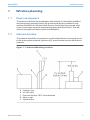
1.2 Antenna location
The antenna should be mounted in a location that allows convenient access
to the host system network (wireless I/O) as well as the wireless field device
network.
Figure 1-1: Antenna Mounting Location
A. Control room
B. RS-485 cable
C. Emerson Wireless 781S Smart Antenna
D. Mast or pipe
E. Infrastructure
March 2020 Quick Start Guide
Quick Start Guide 5

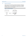
1.3 Antenna position
The Emerson 781S Smart Antennas should be positioned vertically and
approximately 3 ft. (1 m) from large structures, buildings, or conductive
surfaces to allow for clear communication to other devices. If installing
multiple antennas, it is important that the antennas have three feet of
horizontal separation from one another.
Figure 1-2: Antenna Position
Quick Start Guide March 2020
6 Emerson.com

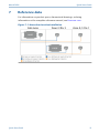
2 Intended use
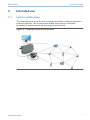
2.1 System architecture
The Smart Antenna must be used in conjunction with a network manager or
network Gateway. The Smart Antenna then functions as a translator
between the wired network and a wireless field network.
Figure 2-1: Example System Architecture
March 2020 Quick Start Guide
Quick Start Guide 7

3 Physical installation
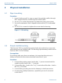
3.1 Pipe mounting
Procedure
1. Insert U-bolt around 2-in. pipe or mast, through the saddle, through
the L-shaped bracket, and through the washer plate.
2. Use a 1/2-in. socket-head wrench to fasten the nuts to the U-bolt.
3. Secure the antenna to the L-shaped bracket with a 5/16-in threaded
bolt.
4. Use a 5/16-in. wrench to tighten the screw into the housing.
Figure 3-1: Mounting
3.2 Power and data wiring
The Emerson 781S is completely prewired and only needs to be connected
and powered on the Gateway end. The housing is permanently sealed on the
Emerson 781S. In the Gateway:
Prerequisites
If operating with more than one antenna, it is important the antenna is
always connected to the antenna terminal connection 1 port.
Procedure
1. Connect the positive power lead to the “+” power terminal and the
negative power lead to the “–” terminal.
2. Connect the data + lead to the “A (+)” terminal and the data – lead to
the “B (–)” terminal.
3. Connect the grounding wire to the Gateway’s shield connection.
4. If connecting multiple antennas, repeat this process for terminal
connection 2.
Quick Start Guide March 2020
8 Emerson.com

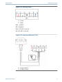
Figure 3-2: Wiring Guide
A. Power
B. Data
Red - positive
Blk - negative
Wht - RS-485 comm A
Blu - RS-485 comm B
Figure 3-3: Emerson Wireless 781S
A. Power output
B. RS-485 comm
March 2020 Quick Start Guide
Quick Start Guide 9

4 Best practices
Twisted shielded pair cable is generally used to wire the serial connection to
the Gateway. The Smart Antenna should be installed in a central location of
the wireless field network so that it has the most direct connections to
wireless devices as possible.
Quick Start Guide March 2020
10 Emerson.com

5 Verify operation
5.1 Emerson 781S Smart Antenna
The antenna has no exterior lights or LCD displays. Therefore, once it is
powered up through the Gateway, its operation must be verified through
the Gateway end of the connection.
5.2 Power up sequence
The second and third LED’s in the Emerson 1410S correlate to the first and
second terminal connections. These lights should be green when the
antenna is connected properly.
5.3 Normal operation
The operation of the WirelessHART
®
Smart Antenna can be assessed within
the Gateway user interface. The connection can be seen by allowing the link
to be seen as a field device. The operability can be verified by attempting to
connect to a device.
March 2020 Quick Start Guide
Quick Start Guide 11

6 Product certifications
Rev 1.2
6.1 European Directive Information
A copy of the EU Declaration of Conformity can be found at the end of the
Quick Start Guide. The most recent revision of the EU Declaration of
Conformity can be found at Emerson.com.
6.2 Telecommunications compliance
All wireless devices require certification to ensure they adhere to regulations
regarding the use of the RF spectrum. Nearly every country requires this type
of product certification. Emerson is working with governmental agencies
around the world to supply fully compliant products and remove the risk of
violating country directives or laws governing wireless device usage.
6.3 FCC and IC
This device complies with Part 15 of the FCC Rules. Operation is subject to
the following conditions: These devices may not cause harmful interference,
this devices must accept any interference received, including interference
that may cause undesired operation. This device must be installed to ensure
a minimum antenna separation distance of 20 cm from all persons. This
device complies with Industry Canada license-exempt RSS-247. Operation is
subject to the following two conditions: (1) this device may not cause
interference, and (2) this device must accept any interference, including
interference that may cause undesired operation of the device.
Changes or modification to the equipment not expressly approved by
Emerson could void the user's authority to operate the equipment.
Cet appareil est conforme à la Partie 15 de la réglementation FCC. Son
fonctionnement est soumis aux conditions suivantes: Cet appareil ne doit
pas causer d'interférences nuisibles. Cet appareil doit accepter toute
interférence reçue, incluant toute interférence pouvant causer un
fonctionnement indésirable. Cet appareil doit être installé pour assurer une
distance minimum de l'antenne de séparation de 20 cm de toute personne.
Cet appareil est conforme à la norme RSS-247 Industrie Canada exempt de
licence. Son fonctionnement est soumis aux deux conditions suivantes: (1)
cet appareil ne doit pas provoquer d'interférences et (2) cet appareil doit
accepter toute interférence, y compris les interférences pouvant causer un
mauvais fonctionnement du dispositif.
Les changements ou les modifications apportés à l'équipement qui n'est pas
expressément approuvé par Rosemount Inc pourraient annuler l'autorité de
l'utilisateur à utiliser cet équipement.
Quick Start Guide March 2020
12 Emerson.com

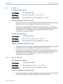
6.4 Europe
I1 ATEX Intrinsic Safety
Certificate
SGS20ATEX0038X
Markings
Ex ia IIC T4 Ga (-40°C ≤ Ta ≤ +70°C)
Standards
EN IEC 60079-0: 2018, EN 60079-11: 2012
Special Conditions for Safe Use (X):
1. The plastic enclosure may constitute a potential electrostatic ignition
risk and must not be rubbed or cleaned with a dry cloth
2. The measured capacitance between the equipment enclosure and
metallic conduit adapter is 21pF. This must be considered only when
the Model 781S is integrated into a system where the process
connection is not grounded.
I1 ATEX Intrinsic Safety
Certificate
SGS20ATEX0053X
Markings
Ex ic IIC T4 Gc (-40°C ≤ Ta ≤ +70°C)
Standards
EN IEC 60079-0: 2018, EN 60079-11: 2012
Special Conditions for Safe Use (X):
1. The plastic enclosure may constitute a potential electrostatic ignition
risk and must not be rubbed or cleaned with a dry cloth
2. The measured capacitance between the equipment enclosure and
metallic conduit adapter is 21pF. This must be considered only when
the Model 781S is integrated into a system where the process
connection is not grounded.
6.5
International
I7 IECEx Intrinsic Safety
Certificate
IECEx BAS.20.0021X
Markings
Ex ia IIC T4 Ga (–40 °C ≤ Ta ≤ +70 °C)
Standards
IEC 60079-0: 2017, IEC 60079-11: 2011
Special Conditions for Safe Use (X):
1. The plastic enclosure may constitute a potential electrostatic ignition
risk and must not be rubbed or cleaned with a dry cloth
March 2020 Quick Start Guide
Quick Start Guide 13

2. The measured capacitance between the equipment enclosure and
metallic conduit adapter is 21pF. This must be considered only when
the Model 781S is integrated into a system where the process
connection is not grounded.
I7 IECEx Intrinsic Safety
Certificate
IECEx BAS 20.0021X
Markings
Ex ic IIC T4 Gc (–40 °C ≤ Ta ≤ +70 °C)
Standards
IEC 60079-0: 2017, IEC 60079-11: 2011
Special Conditions for Safe Use (X):
1. The plastic enclosure may constitute a potential electrostatic ignition
risk and must not be rubbed or cleaned with a dry cloth
2. The measured capacitance between the equipment enclosure and
metallic conduit adapter is 21pF. This must be considered only when
the Model 781S is integrated into a system where the process
connection is not grounded.
Quick Start Guide March 2020
14 Emerson.com

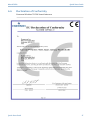
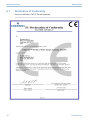
6.6 Declaration of Conformity
Emerson Wireless 781SA Smart Antenna
March 2020 Quick Start Guide
Quick Start Guide 15

Quick Start Guide March 2020
16 Emerson.com

March 2020 Quick Start Guide
Quick Start Guide 17

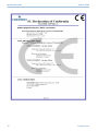
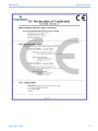
6.7 Declaration of Conformity
Emerson Wireless 781SC Smart Antenna
Quick Start Guide March 2020
18 Emerson.com

March 2020 Quick Start Guide
Quick Start Guide 19

Quick Start Guide March 2020
20 Emerson.com
La page est en cours de chargement...
La page est en cours de chargement...
La page est en cours de chargement...
La page est en cours de chargement...
-
 1
1
-
 2
2
-
 3
3
-
 4
4
-
 5
5
-
 6
6
-
 7
7
-
 8
8
-
 9
9
-
 10
10
-
 11
11
-
 12
12
-
 13
13
-
 14
14
-
 15
15
-
 16
16
-
 17
17
-
 18
18
-
 19
19
-
 20
20
-
 21
21
-
 22
22
-
 23
23
-
 24
24


Emerson Wireless 781S Smart Antenna Guide de démarrage rapide
- Taper
- Guide de démarrage rapide
dans d''autres langues
Documents connexes
Autres documents
-
Rosemount Wireless Pressure Gauge Guide de démarrage rapide
-
Rosemount 1408H Non-Contacting Radar Level Transmitter Guide de démarrage rapide
-
-
Asco Series NFIS WSNFIS Low Power Solenoid Le manuel du propriétaire
-
-
-
-
-
AMS Wireless Vibration Monitor Mode d'emploi
-