Rosemount Wireless Pressure Gauge Guide de démarrage rapide
- Taper
- Guide de démarrage rapide

Quick Start Guide
00825-0100-4045, Rev BB
February 2019
Rosemount
™
Wireless Pressure Gauge
with WirelessHART
®
Protocol

February 2019
2
Quick Start Guide
Required equipment
NOTICE
This guide provides basic guidelines for Rosemount Wireless Pressure Gauges. It does not provide
instructions for configuration, diagnostics, maintenance, service, troubleshooting or intrinsically safe (I.S.)
installations. Refer to the Rosemount Wireless Pressure Gauge
Reference Manual for more instruction. The
manual and this guide are also available electronically on
Emerson.com\Rosemount.
Shipping considerations
The unit is shipped with the battery installed.
Each device contains one “D” size primary lithium-thionyl chloride battery. Primary lithium batteries are
regulated in transportation by the U.S. Department of Transportation, and are also covered by IATA
(International Air Transport Association), ICAO (International Civil Aviation Organization), and ARD
(European Ground Transportation of Dangerous Goods). It is the responsibility of the shipper to ensure
compliance with these or any other local requirements. Consult current regulations and requirements before
shipping.
Explosions could result in death or serious injury.
Installation of device in an explosive environment must be in accordance with appropriate local, national
and international standards, codes, and practices.
Ensure device is installed in accordance with intrinsically safe or non-incendive field practices.
Electrical shock can result in death or serious injury.
Care must be taken during transportation of device to prevent electrostatic charge build-up.
Device must be installed to ensure a minimum antenna separation distance of 8 in. (20 cm) from all
persons.
Process leaks could result in death or serious injury.
Handle the transmitter carefully.
Failure to follow safe installation guidelines could result in death or serious injury.
Only qualified personnel should install the equipment.
Anti-seize paste or PTFE tape
(for NPT threaded connection)
Standard tools, e.g. screwdriver,
wrench, pliers
AMS Wireless Configurator version
12.0 or later, or Field Communicator
Contents
What’s in the box . . . . . . . . . . . . . . . . . . . . . . . . . 3
Optional: Power/device check . . . . . . . . . . . . . 4
Optional: Normal range indication option . . . 4
Installation procedure . . . . . . . . . . . . . . . . . . . . 5
Troubleshooting . . . . . . . . . . . . . . . . . . . . . . . . . 8
Product Certifications . . . . . . . . . . . . . . . . . . . . . 9
AMS

Quick Start Guide
3
February 2019
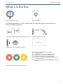
What’s in the box
The following options are also available and will ship with the Rosemount Wireless
Pressure Gauge if ordered.
Wireless Pressure Gauge Quick Start Guide
Rosemount 306 Integral Manifold (Model code S5) B4 Bracket (Model code B4)
Rosemount 1199 Seal (Model code S1)
Product Certification (Model Codes below)
Q4: Calibration Cert
QG: Calibration Cert and GOST Verification Cert
QP: Calibration Cert and Tamper Evident Seal
Q8: Material Traceability cert per EN 102043.1
Q15: Cert of Compliance to NACE MR0175/ISO 15156
for wetted materials
Q25: Cert of Compliance to NACE MR00103 for wetted
materials
Normal Range Indication (Model code LK)

February 2019
4
Quick Start Guide
1.0 Optional: Power/device check
The device is designed to be installation-ready. To check device battery prior to
installation, perform the following:
1. Perform “Turn on device” on page 6.
2. Slide the ON/OFF switch to the OFF position until ready for use.
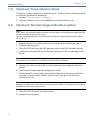
2.0 Optional: Normal range indication option
Note
The stickers are intended to be installed on the dial only and should not be applied on the
inside or outside of the housing cover.
Stickers should be applied in an environment where the ambient temperature is above
50 °F (10 °C).
1. Modify each of the stickers to desired size prior to proceeding to step 2.
2. Remove housing cover.
3. Slide ON/OFF switch to the OFF position and wait for LED to stop flashing.
4. Gently move the needle in the clockwise direction until it is pointing at the
Red X.
Note
Use caution as the electronics assembly is connected to the needle.
5. Remove any debris on the dial, so it does not become trapped under the
sticker.
6. Peel back the white paper backing of the sticker.
7. Slowly lower the sticker onto the surface of the dial in the desired location
and rub it in place firmly. Repeat steps 6 and 7 until desired indication
locations are set.
Note
Moving the sticker after initial contact is not recommended as this decreases the amount
of adhesive on the back of the sticker.
8. Slide ON/OFF switch to the ON position.
9. Replace housing cover.

Quick Start Guide
5
February 2019
3.0 Installation procedure
Step 1: Seal and protect threads
Step 2: Mount device
Note
Use wrench on flats, not on housing.
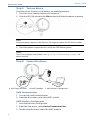
Mounting orientation
The low side pressure port (atmospheric reference) on the process pressure
gauge is located in the neck of the device behind the housing. The vent path is
between the housing and sensor (see Figure 1).
Figure 1. Low Side Pressure Port
A. Low side pressure port (atmospheric reference)
Keep the vent path free of any obstruction, including but not limited to paint, dust, and lubrication by
mounting the device so the process can drain away.
OR
A

February 2019
6
Quick Start Guide
Step 3: Turn on device
Check to ensure the device and battery are working properly.
1. Twist the cover counterclockwise to remove it.
2. Slide the OFF/ON switch to the ON position to initiate the power sequence.
Note
During the power sequence, the dial tests full range of motion and LED flashes amber.
3. Once the power sequence ends, verify the LED flashes green.
Note
The LED may display several colors; see Figure 1 in “Troubleshooting” on page 8 for
device statuses.
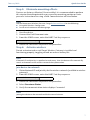
Step 4: Connect to device
Field Communicator
1. Turn on the Field Communicator.
2. From the Main menu, select the HART symbol.
AMS Wireless Configurator
1. Start AMS Wireless Configurator.
2. From the View menu, select Device Connection View.
3. Double click the device under the HART modem.
A. Field Communicator B. HART
®
Modem C. AMS Wireless Configurator
123
645
87
0
9
A
B
C

Quick Start Guide
7
February 2019
Step 5: Eliminate mounting effects
Devices are factory-calibrated. Once installed, it is recommended to perform
this step to eliminate potential error caused by mounting position or static
pressure. Instructions for using a Field Communicator are listed below.
Note
See the Rosemount Wireless Pressure Gauge Reference Manual for the following:
Using AMS Wireless Configurator
Sensor trim function on absolute gauge
1. Vent the device.
2. Connect the Field Communicator.
3. From the HOME screen, enter the HART Fast Key sequence.
4. Follow the commands to perform the procedure.
Step 6: Activate wireless
Do not activate wireless until Smart Wireless Gateway is installed and
functioning properly; toggling off and on reduces battery life.
Note
If Network ID and Join Key is specified at order entry, then the device will automatically
search and connect to the wireless network when powered on.
Join device to network
1. Obtain Network ID and Join Key for the wireless network (available in wireless
gateway).
2. From the HOME screen, enter the HART Fast Key sequence.
3. Follow the commands to perform the procedure.
4. Select Overview>Status.
5. Verify the communication status displays Connected.
Note
Joining the device to the network could take several minutes.
Device dashboard Fast Keys
2, 1, 1
Device dashboard Fast Keys
2, 1, 2

February 2019
8
Quick Start Guide
4.0 Troubleshooting
This section provides information for basic troubleshooting. See the reference
manual (document number 00809-0100-4045) for advanced
troubleshooting .
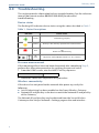
Device status
The flashing LED indicates device status using the colors descibed in Table 1.
Table 1. Status Descriptions
Pressure measurement
If the mounting effects have not been eliminated after completing Step 5,
perform this alternative procedure for verifying the pressure value.
1. From the HOME screen, eter the HART Fast Key sequence.
2. Follow the commands to perform the procedure.
Wireless connectivity
If the device has not joined to the network after power up, verify the
following:
Active Advertising has been enabled on the Smart Wireless Gateway
Network ID and Join Key in the device match the Network ID and Join Key
of the Gateway
The Network ID and Join Key may be obtained from the Smart Wireless
Gateway on the Setup > Network > Settings page on the web interface .
LED color Device status
Green Functioning properly
Amber Battery is low, battery replacement recommended
Red
Battery replacement required
OR
Device is malfunctioning
No
color
No power, verify ON/OFF switch is in “on” position
Device dashboard Fast Keys
2, 2, 1, 1, 1

Quick Start Guide
9
February 2019
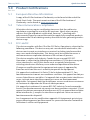
5.0 Product Certifications
Rev: 2.0
5.1 European Directive Information
A copy of the EU Declaration of Conformity can be found at the end of the
Quick Start Guide. The most recent revision of the EU Declaration of
Conformity can be found at
www.emerson.com.
5.2 Telecommunication compliance
All wireless devices require certification to ensure that they adhere to
regulations regarding the use of the RF spectrum. Nearly every country
requires this type of product certification. Emerson
™
is working with
governmental agencies around the world to supply fully compliant products
and remove the risk of violating country directives or laws governing wireless
device usage.
5.3 FCC and IC
This device complies with Part 15 of the FCC Rules. Operation is subject to the
following conditions: This devices may not cause harmful interference, this
devices must accept any interference received, including interference that
may cause undesired operation. This device must be installed to ensure a
minimum antenna separation distance of 20 cm from all persons.
This device complies with Industry Canada license-exempt RSS-247.
Operation is subject to the following two conditions: (1) this device may not
cause interference, and (2) this device must accept any interference,
including interference that may cause undesired operation of the device.
Changes or modification to the equipment not expressly approved by
Emerson could void the user's authority to operate the equipment.
Cet appareil est conforme à la Partie 15 de la réglementation FCC. Son
fonctionnement est soumis aux conditions suivantes: Cet appareil ne doit pas
causer d'interférences nuisibles. Cet appareil doit accepter toute interférence
reçue, incluant toute interférence pouvant causer un fonctionnement
indésirable. Cet appareil doit être installé pour assurer une distance minimum
de l'antenne de séparation de 20 cm de toute personne.
Cet appareil est conforme à la norme RSS-247 Industrie Canada exempt de
licence. Son fonctionnement est soumis aux deux conditions suivantes: (1) cet
appareil ne doit pas provoquer d'interférences et (2) cet appareil doit accepter
toute interférence, y compris les interférences pouvant causer un mauvais
fonctionnement du dispositif.
Les changements ou les modifications apportés à l'équipement qui n'est pas
expressément approuvé par Rosemount Inc. pourraient annuler l'autorité de
l'utilisateur à utiliser cet équipement.

February 2019
10
Quick Start Guide
5.4 Ordinary Location Certification from CSA
The product has been examined and tested to determine that the design meets
the basic electrical, mechanical, and fire protection requirements by CSA, a
nationally recognized test laboratory (NRTL) as accredited by the Federal
Occupational Safety and Health Administration (OSHA).
5.5 Installing in North America
The US National Electrical Code (NEC) and the Canadian Electrical Code (CEC)
permit the use of Division marked equipment in Zones and Zone marked
equipment in Divisions. The markings must be suitable for the area
classification, gas, and temperature class. This information is clearly defined in
the respective codes.
5.6 USA
I5 U.S.A. Intrinsically Safe (IS)
Certificate: [CSA] 70047656
Standards: FM 3600 – 2011, FM 3610 – 2010, UL Standard 50 – Eleventh Edition,
UL 61010-1 – 3rd Edition, ANSI/ISA-60079-0 (12.00.01) – 2013,
ANSI/ISA-60079-11 (12.02.01) – 2013, ANSI/IEC 60529 – 2004
Markings: IS CL I, DIV 1, GP A, B, C, D T4;
Class 1, Zone 0, AEx ia IIC T4 Ga;
T4 (-40 °C Ta +70 °C)
when installed per Rosemount drawing 00G45-1020;
Type 4X; IP66/67;
Special Conditions for Safe Use (X):
1. Do not replace battery when explosive atmosphere is present.
2. Use only 00G45-9000-0001 batteries.
3. The surface resistivity of the housing is greater than 1G . To avoid electrostatic
charge build-up, it must not be rubbed or cleaned with solvents or a dry cloth.
4. Substitution of components may impair intrinsic safety.
5.7 Canada
I6 Canada Intrinsically Safe (IS)
Certificate: [CSA] 70047656
Standards: CAN/CSA C22.2 No. 0-10, CAN/CSA C22.2 No. 94-M1991 (R2011),
CAN/CSA-60079-0-11, CAN/CSA-60079-11-14, CSA Std C22.2 No. 60529-05,
CAN/CSA-C22.2 No. 61010-1-12
Markings: Intrinsically Safe for Class I, Division 1, Groups A, B, C, D T4;
Ex ia IIC T4 Ga
T4 (-50 °C Ta +70 °C)
when installed per Rosemount drawing 00G45-1020;
Type 4X; IP66/67;
Special Conditions for Safe Use (X):
1. Do not replace battery when explosive atmosphere is present.
Ne pas remplacer les accumulateurs si une atmosphère explosive peut être présente.
2. Use only 00G45-9000-0001 batteries.
Utiliser uniquement des accumulateurs 00G45-9000-0001.
3. The surface resistivity of the housing is greater than 1G . To avoid electrostatic
charge build-up, it must not be rubbed or cleaned with solvents or a dry cloth.

Quick Start Guide
11
February 2019
La résistivité de surface du boÎtier est supérieure à un gigaohm. Pour éviter
l’accumulation de charge électrostatique, ne pas frotter ou nettoyer avec des produits
solvants ou un chiffon sec.
4. Substitution of components may impair intrinsic safety.
La substitution de composants peut compromettre la sécurité intrinsèque.
5.8 Europe
I1 ATEX Intrinsic Safety
Certificate: Baseefa16ATEX0005X
Standards: EN 60079-0: 2012 + A11: 2013, EN 60079-11: 2012
Markings: II 1 G Ex ia IIC T4 Ga, T4 (-40 °C Ta +70 °C)
IP66/67;
Special Conditions for Safe Use (X):
1. The plastic enclosure may constitute a potential electrostatic ignition risk and must
not be rubbed or cleaned with a dry cloth.
2. The measured capacitance between the equipment enclosure and metallic inline
sensor module is 4.7pF. This must be considered only when the WPG is integrated into
a system where the process connection is not grounded.
3. Do not change the battery when an explosive atmosphere is present.
4. Only replace battery with Rosemount Part No. 00G45-9000-0001.
5.9 International
I7 IECEx Intrinsic Safety
Certificate: IECEx BAS 16.0012X
Standards: IEC 60079-0: 2011, IEC 60079-11: 2011
Markings: Ex ia IIC T4 Ga, T4 (-40 °C Ta +70 °C)
IP66/67;
Special Conditions for Safe Use (X):
1. The plastic enclosure may constitute a potential electrostatic ignition risk and must
not be rubbed or cleaned with a dry cloth.
2. The measured capacitance between the equipment enclosure and metallic inline
sensor module is 4.7pF. This must be considered only when the WPG is integrated into
a system where the process connection is not grounded.
3. Do not change the battery when an explosive atmosphere is present.
4. Only replace battery with Rosemount Part No. 00G45-9000-0001.
5.10 Brazil
I2 INMETRO Intrinsic Safety
Certificate: UL-BR 16.0826X
Standards: ABNT NBR IEC 60079-0:2008 + Errata 1:2011, ABNT NBR IEC 60079-11:2009
Markings: Ex ia IIC T4 Ga, T4 (-40°C Ta +70°C)
Special Conditions for Safe Use (X):
See certificate for special conditions

February 2019
12
Quick Start Guide
5.11 Japan
I4 TIIS Intrinsic Safety
Certificate: TC22068X
Markings: Ex ia IIC T4 Ga, T4 (-40°C Ta +70°C)
Special Conditions for Safe Use (X):
See certificate for special conditions
5.12 EAC – Belarus, Kazakhstan, Russia
IM Technical Regulation Customs Union (EAC) Intrinsic Safety
Certificate: TC RU C-US.AA87.B.00372
Markings: 0Ex ia IIC T4 Ga X, T4 (-40°C Ta +70°C) IP66/67;
Special Conditions for Safe Use (X):
See certificate for special conditions

Quick Start Guide
13
February 2019
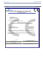
Figure 2. Rosemount Wireless Pressure Gauge Declaration of Conformity
EU Declaration of Conformity
No: RMD 1108 Rev. E
Page 1 of 3
We,
Rosemount Inc.
8200 Market Boulevard
Chanhassen, MN 55317-9685
USA
declare under our sole responsibility that the product,
Models WPG & SPG:
Wireless Pressure Gauge & Smart Pressure Gauge
manufactured by,
Rosemount Inc.
8200 Market Boulevard
Chanhassen, MN 55317-9685
USA
to which this declaration relates, is in conformity with the provisions of the European
Community Directives, including the latest amendments, as shown in the attached schedule.
Assumption of conformity is based on the application of the harmonized standards and, when
applicable or required, a European Community notified body certification, as shown in the
attached schedule.
(si
g
nature)
Vice President of Global Quality
(function name - printed)
Chris LaPoint
(name - printed)
1-Feb-19
(date of issue)

February 2019
14
Quick Start Guide
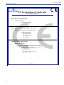
EU Declaration of Conformity
No: RMD 1108 Rev. E
Page 2 of 3
EMC Directive (2014/30/EU)
Models WPG & SPG
Harmonized Standards:
EN 61326-1: 2013
Radio Equipment Directive (RED) (2014/53/EU)
Model WPG (Wireless Pressure Gauge only)
Harmonized Standards:
EN 300 328 V2.1.1
EN 301 489-1 V2.2.0
EN 301 489-17: V3.2.0
EN 61010-1: 2010
EN 62479: 2010
ATEX Directive (2014/34/EU)
Models WPG & SPG
Baseefa16ATEX0005X - Intrinsic Safety Certificate
Equipment Group II Category 1 G
Ex ia IIC T4 Ga, T4(-40°C Ta +70°C)
Harmonized Standards:
EN 60079-0: 2012 + A11: 2013
EN 60079-11: 2012

Quick Start Guide
15
February 2019
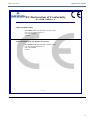
EU Declaration of Conformity
No: RMD 1108 Rev. E
Page 3 of 3
ATEX Notified Bodies
SGS FIMCO OY [Notified Body Number: 0598]
P.O. Box 30 (Särkiniementie 3)
00211 HELSINKI
Finland
ATEX Notified Body for Quality Assurance
SGS FIMCO OY [Notified Body Number: 0598]
P.O. Box 30 (Särkiniementie 3)
00211 HELSINKI
Finland

February 2019
16
Quick Start Guide
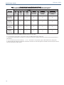
ਜ਼
ਜ਼ᴹ
China RoHS
㇑
㇑᧗⢙䍘䎵䗷ᴰབྷ⎃ᓖ䲀٬Ⲵ䜘Ԧරਧࡇ㺘
Rosemount SPG
List of
Rosemount SPG
Parts with China RoHS Concentration above MCVs
䜘
䜘Ԧ〠
Part Name
ᴹ
ᴹᇣ⢙
䍘
䍘
/ Hazardous Substances
䫵
䫵
Lead
(Pb)
⊎
⊎
Mercury
(Hg)
䭹
䭹
Cadmium
(Cd)
ޝ
ޝԧ
䬜
䬜
Hexavalent
Chromium
(Cr +6)
ཊ
ཊⓤ
㚄
㚄㤟
Polybrominated
biphenyls
(PBB)
ཊ
ཊⓤ
㚄
㚄㤟䟊
Polybrominated
diphenyl ethers
(PBDE)
⭥ᆀ㓴Ԧ
Electronics
Assembly
XO O O O O
༣փ㓴Ԧ
Housing
Assembly
OO O O O O
Րᝏಘ㓴Ԧ
Sensor
Assembly
XO O O O O
⭥⊐㓴Ԧ
Battery
Assembly
XO O O O O
ᵜ㺘Ṭ㌫ᦞ
SJ/T11364
Ⲵ㿴ᇊ㘼ࡦ
This table is proposed in accordance with the provision of SJ/T11364.
O:
Ѫ䈕䜘ԦⲴᡰᴹ൷䍘ᶀᯉѝ䈕ᴹᇣ⢙䍘Ⲵਜ਼䟿൷վҾ
GB/T 26572
ᡰ㿴ᇊⲴ䲀䟿㾱≲
O: Indicate that said hazardous substance in all of the homogeneous materials for this part is below the limit requirement of
GB/T 26572.
X:
Ѫ൘䈕䜘Ԧᡰ֯⭘Ⲵᡰᴹ൷䍘ᶀᯉ䟼ˈ㠣ቁᴹа㊫൷䍘ᶀᯉѝ䈕ᴹᇣ⢙䍘Ⲵਜ਼䟿儈Ҿ
GB/T 26572
ᡰ㿴ᇊⲴ䲀䟿㾱≲
X: Indicate that said hazardous substance contained in at least one of the homogeneous materials used for this part is above
the limit requirement of GB/T 26572.

Quick Start Guide
17
February 2019

Global Headquarters
Emerson Automation Solutions
6021 Innovation Blvd.
Shakopee, MN 55379, USA
+1 800 999 9307 or +1 952 906 8888
+1 952 949 7001
North America Regional Office
Emerson Automation Solutions
8200 Market Blvd.
Chanhassen, MN 55317, USA
+1 800 999 9307 or +1 952 906 8888
+1 952 949 7001
Latin America Regional Office
Emerson Automation Solutions
1300 Concord Terrace, Suite 400
Sunrise, FL 33323, USA
+1 954 846 5030
+1 954 846 5121
Linkedin.com/company/Emerson-Automation-Solutions
Twitter.com/Rosemount_News
Facebook.com/Rosemount
Youtube.com/user/RosemountMeasurement
Google.com/+RosemountMeasurement
Emerson Terms and Conditions of Sale are available upon request
The Emerson logo is a trademark and service mark of Emerson
Electric Co.
Rosemount and Rosemount logotype are trademarks of Emerson.
All other marks are the property of their respective owners.
© 2019 Emerson. All rights reserved.
Europe Regional Office
Emerson Automation Solutions
Neuhofstrasse 19a P.O. Box 1046
CH 6340 Baar
Switzerland
+41 (0) 41 768 6111
+41 (0) 41 768 6300
Asia Pacific Regional Office
Emerson Automation Solutions
1 Pandan Crescent
Singapore 128461
+65 6777 8211
+65 6777 0947
Middle East and Africa Regional Office
Emerson Automation Solutions
Emerson FZE P.O. Box 17033
Jebel Ali Free Zone - South 2
Dubai, United Arab Emirates
+971 4 8118100
+971 4 8865465
Quick Start Guide
00825-0100-4045, Rev BB
February 2019
*00825-0100-4045*
-
 1
1
-
 2
2
-
 3
3
-
 4
4
-
 5
5
-
 6
6
-
 7
7
-
 8
8
-
 9
9
-
 10
10
-
 11
11
-
 12
12
-
 13
13
-
 14
14
-
 15
15
-
 16
16
-
 17
17
-
 18
18


Rosemount Wireless Pressure Gauge Guide de démarrage rapide
- Taper
- Guide de démarrage rapide
dans d''autres langues
Documents connexes
Autres documents
-
Emerson Wireless 781S Smart Antenna Guide de démarrage rapide
-
AMS Wireless Vibration Monitor Mode d'emploi
-
 Remote Automation Solutions FloBoss 103 Mode d'emploi
-
 Remote Automation Solutions FloBoss 104 Flow Manager Mode d'emploi
-
 Remote Automation Solutions FloBoss 104 Flow Manager Mode d'emploi
-
Emerson D301801X012 Mode d'emploi
-
-
 Remote Automation Solutions DL8000 Preset Controller Mode d'emploi
-
Siemens SITRANS LR25 Guide de démarrage rapide
-
Emerson Sewing Machine MSM400 Manuel utilisateur


