Rosemount 1408H Non-Contacting Radar Level Transmitter Guide de démarrage rapide
- Taper
- Guide de démarrage rapide

Quick Start Guide
00825-0100-4480, Rev AA
October 2020
Rosemount
™
1408H
Level Transmitter
Non-Contacting Radar

1 About this guide
This Quick Start Guide provides basic guidelines for the Rosemount
1408H Level Transmitter. Refer to the 1408H Reference Manual for
more instructions.
1.1 Safety messages
WARNING
Failure to follow safe installation and servicing guidelines could result
in death or serious injury.
• Ensure the transmitter is installed by qualified personnel and in
accordance with applicable code of practice.
• Use the equipment only as specified in this Quick Start Guide and
the Reference Manual. Failure to do so may impair the protection
provided by the equipment.
• Repair, e.g. substitution of components, etc. may jeopardize
safety and is under no circumstances allowed.
Process leaks could result in death or serious injury.
• Handle the transmitter carefully.
• Install and tighten process connectors before applying pressure.
• Do not attempt to loosen or remove process connectors while the
transmitter is in service.
2

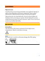
WARNING
Physical access
Unauthorized personnel may potentially cause significant damage to
and/or misconfiguration of end users’ equipment. This could be
intentional or unintentional and needs to be protected against.
Physical security is an important part of any security program and
fundamental to protecting your system. Restrict physical access by
unauthorized personnel to protect end users’ assets. This is true for all
systems used within the facility.
CAUTION
Hot surfaces
The transmitter and process seal may be hot at high process
temperatures. Allow to cool before servicing.
Note
Be careful not to scratch or otherwise damage the PTFE sealing.
3

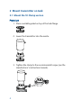
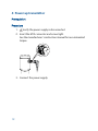
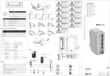
2 Mount transmitter on tank
2.1 Mount the Tri Clamp version
Procedure
1.
Place a suitable gasket on top of the tank flange.
2. Lower the transmitter into the nozzle.
3. Tighten the clamp to the recommended torque (see the
manufacturer’s instruction manual).
4

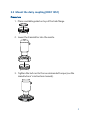
2.2 Mount the dairy coupling (DIN 11851)
Procedure
1.
Place a suitable gasket on top of the tank flange.
2. Lower the transmitter into the nozzle.
3. Tighten the lock nut to the recommended torque (see the
manufacturer’s instruction manual).
5

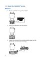
2.3 Mount the VARIVENT
®
version
Procedure
1.
Mount a suitable O-ring on the adapter.
2. Lower the transmitter into the nozzle.
3. Tighten the clamp to the recommended torque (see the
manufacturer’s instruction manual).
6

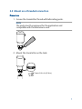
2.4 Mount on a threaded connection
Procedure
1.
Grease the transmitter thread with lubricating paste.
Note
The paste must be approved for the application and
compatible with the elastomers used.
2. Mount the transmitter on the tank.
39 mm
Torque 310 in-lb (35 N-m)
7

3 Prepare the electrical connections
3.1 Connector type
M12 (A-coded)
3.2
Power supply
The transmitter operates on 18-30 Vdc at the transmitter terminals.
3.3 Outputs
The transmitter provides two configurable outputs:
Output 1
Digital output / IO-Link mode
Output 2
Digital output or active 4-20 mA analog output
3.4 Internal power consumption
< 2 W (normal operation at 24 Vdc, no outputs)
< 3.6 W (normal operation at 24 Vdc, digital and analog outputs
active)
3.5
Wiring diagram
Figure 3-1: Connection
4
1
3
2
BN
W
H
BK
BU
1
4
2
3
OUT2
L+
L
OUT1/IO-Link
8

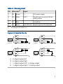
Table 3-1: Pin Assignment
Pin Wire color
(1)
Signal
1 BN Brown L+ 24 V power supply
2 WH White OUT2 Digital output or active 4-20 mA
analog output
3 BU Blue L- Ground line
4 BK Black OUT1/IO-Link Digital output or IO-Link mode
(1)
According to IEC 60947-5-2.
Figure 3-2: Example Circuits
2: OUT2
4: OUT1
4
1
3
2
BN
WH
BK
BU
L+
L
A
2: O
UT2
4: OUT1
4
1
3
2
BN
W
H
BK
BU
L+
L
C
2: O
UT2
4: OUT1
4
1
3
2
BN
WH
BK
BU
L+
L
D
4
1
3
2
BN
WH
BK
BU
L+
L
2: OUT2
4: OUT1
B
A. 2 x Digital output PnP
B. 2 x Digital output NpN
C. 1 x Digital output PnP / 1 x Analog output
D. 1 x Digital output NpN / 1 x Analog output
9

4 Power up transmitter
Prerequisites
Procedure
1.
Verify the power supply is disconnected.
2. Insert the M12 connector and screw tight.
See the manufacturer’s instruction manual for recommended
torque.
3. Connect the power supply.
10

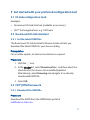
5 Get started with your preferred configuration tool
5.1 IO-Link configuration tools
Examples:
• Rosemount IO-Link Assistant (available as accessory)
• FDT
®
frame applications, e.g. PACT
ware
5.2 Rosemount IO-Link Assistant
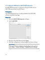
5.2.1 Get the latest IODD files
The Rosemount IO-Link Assistant software checks and lets you
download the latest IODDs for your device catalog.
Prerequisites
For an online update, an internet connection is required.
Procedure
1. Click the
icon.
2.
In the
Vendor list, select Rosemount Inc., and then select the
check box for the devices to be installed/updated.
Alternatively, select Browsing and navigate to an already
downloaded IODD file.
3. Select OK.
5.3 FDT
®
/DTM framework
5.3.1 Download the IODD file
Procedure
Download the IODD from the IODDFinder portal at
Ioddfinder.io-link.com.
11

5.3.2 Integrate IODDs into an FDT
®
/DTM framework
An IODD DTM Interpreter is required to integrate IODDs into an
FDT/DTM environment (e.g PACTware).
Prerequisites
The IODD DTM Interpreter is usually included in the FDT/DTM
software installation package.
Procedure
1.
Start the
IODD DTM Interpreter software.
2. Select Add IODD.
3. Browse to the IODD file and select Open.
4. Start the configuration tool and update the device catalog.
Need help?
If the new DTM is not added automatically at start-up, then
select
View → Device Catalog → Update Device Catalog.
12

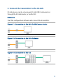
6 Connect the transmitter to the IO-Link
IO-Link devices can be set using an IO-Link USB Communicator,
through the IO-Link master, or via the PLC.
Procedure
Start the configuration software and connect the transmitter.
Figure 6-1: Connection via the IO-Link USB Communicator
Figure 6-2: Connection via the IO-Link Master
Figure 6-3: Connection via the PLC
13

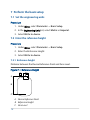
7 Perform the basic setup
7.1 Set the engineering units
Procedure
1.
Under Menu, select Parameter → Basic Setup.
2. In the Engineering Units list, select Metric or Imperial.
3. Select Write to device.
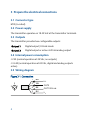
7.2 Enter the reference height
Procedure
1. Under Menu, select Parameter → Basic Setup.
2. Enter the Reference Height.
3. Select Write to device.
7.2.1 Reference height
Distance between the Device Reference Point and Zero Level.
Figure 7-1: Reference Height
A
B
C
A. Device Reference Point
B. Reference Height
C. Zero Level
14

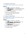
7.3 Configure the analog output
The transmitter can be set to output the level as a 4-20 mA signal.
Procedure
1.
Under
Menu, select Parameter → Basic Setup.
2. In the OUT2 Configuration list, select Analog Output 4-20 mA.
3. In the Alarm Mode list, select Low Alarm or High Alarm.
4. Select OUT2 → Analog Output 2.
5. Enter the desired Upper Range Value (20 mA).
6. Enter the desired Lower Range Value (4 mA).
7. Select Write to device.
7.4 Configure the digital output
The transmitter can be set to output a switching signal for high and
low level limits (using the same pin).
Procedure
1. Under Menu, select Parameter → Basic Setup.
2. In the OUT1 Configuration or OUT2 Configuration list, select
Digital Output Normally Open.
3. In the Digital Outputs P-n list, select PnP or nPn.
4. Select Digital Output 1 or Digital Output 2.
5. Set the alarm parameters as desired.
6. Select Write to device.
15

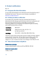
8 Product certifications
Rev 1.0
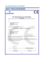
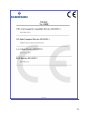
8.1 European directive information
A copy of the EU Declaration of Conformity can be found at the end of
the Quick Start Guide. The most current revision is available at
Emerson.com/Rosemount
.
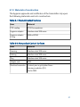
8.2 Ordinary location certification
As standard, the transmitter has been examined and tested to
determine that the design meets the basic electrical, mechanical, and
fire protection requirements by a nationally recognized test
laboratory (NRTL) as accredited by the Federal Occupational Safety
and Health Administration (OSHA).
Certificate
80031621
Standards
CAN/CSA-C22.2 No. 61010-1-12,
UL Std. No. 61010-1
Markings
18-30 VDC, 3.6W; IP66, IP68, IP69; 8 bar
The device may only be powered by a power supply unit with a limited
energy electric circuit max. 30 Vdc output in accordance with CAN/
CSA-C22.2 No. 61010-1-12 / UL Std. No. 61010-1 (3rd Edition)
chapter 6.3.1/6.3.2 and 9.4 or class 2 according to CSA 223/UL 1310.
8.3 Telecommunication compliance
Measurement principle
Frequency Modulated Continuous Wave (FMCW), 80 GHz
Maximum output power
3 dBm (2 mW)
16

Frequency range
77 to 81 GHz
TLPR (Tank Level Probing Radar)
TLPR (Tank Level Probing Radar) equipment are devices for
measurement of level in a closed space only (i.e metallic or reinforced
concrete or fiberglass tanks, or similar enclosure structures made of
comparable attenuating material). Rosemount 1408H is TLPR device.
Hardware Version Identification Number (HVIN) is 1408T.
8.4 FCC
Note: This equipment has been tested and found to comply with the
limits for a Class B digital device, pursuant to part 15 of the FCC Rules.
These limits are designed to provide reasonable protection against
harmful interference in a residential installation. This equipment
generates, uses and can radiate radio frequency energy and, if not
installed and used in accordance with the instructions, may cause
harmful interference to radio communications. However, there is no
guarantee that interference will not occur in a particular installation. If
this equipment does cause harmful interference to radio or television
reception, which can be determined by turning the equipment off and
on, the user is encouraged to try to correct the interference by one or
more of the following measures:
• Reorient or relocate the receiving antenna.
• Increase the separation between the equipment and receiver.
• Connect the equipment into an outlet on a circuit different from
that to which the receiver is connected.
• Consult the dealer or an experienced radio/TV technician for help.
FCC ID
K8C1408T
17

8.5 IC
This device complies with Industry Canada’s licence-exempt RSS
standard. Operation is subject to the following conditions:
1.
This device may not cause harmful interference.
2.
This device must accept any interference received, including
interference that may cause undesired operation.
3. The installation of the TLPR device shall be done by trained
installers in strict compliance with the manufacturer’s
instructions.
4. The use of this device is on a “no-interference, no-protection”
basis. That is, the user shall accept operations of high-powered
radar in the same frequency band which may interfere with or
damage this device. However, devices found to interfere with
primary licensing operations will be required to be removed at
the user’s expense.
5. This device shall be installed and operated in a completely
enclosed container to prevent RF emissions, which can
otherwise interfere with aeronautical navigation.
6. The installer/user of this device shall ensure that it is at least 10
km from the Dominion Astrophysical Radio Observatory
(DRAO) near Penticton, British Columbia. The coordinates of
the DRAO are latitude 49°19′15″N and longitude 119°37′12″
W. For devices not meeting this 10 km separation (e.g., those
in the Okanagan Valley, British Columbia,) the installer/user
must coordinate with, and obtain the written concurrence of,
the Director of the DRAO before the equipment can be
installed or operated. The Director of the DRAO may be
contacted at 250-497-2300 (tel.) or 250-497-2355 (fax).
(Alternatively, the Manager, Regulatory Standards, Industry
Canada, may be contacted.)
18

Le présent appareil est conforme aux CNR d'Industrie Canada
applicables aux appareils radio exempts de licence. L'exploitation est
autorisée aux conditions suivantes:
1. l'appareil ne doit pas produire de brouillage.
2.
l'appareil doit accepter tout brouillage radioélectrique subi,
même si le brouillage est susceptible d'en compromettre le
fonctionnement.
3. L’installation d’un dispositif TLPR doit être effectuée par des
installateurs qualifiés, en pleine conformité avec les
instructions du fabricant.
4. Ce dispositif ne peut être exploité qu'en régime de non-
brouillage et de non-protection, c'est-à-dire que l'utilisateur
doit accepter que des radars de haute puissance de la même
bande de fréquences puissent brouiller ce dispositif ou même
l'endommager. D'autre part, les capteurs de niveau qui
perturbent une exploitation autorisée par licence de
fonctionnement principal doivent être enlevés aux frais de leur
utilisateur.
5. Un dispositif visé comme TLPR doit être installé et exploité
dans un réservoir entièrement fermé afin de prévenir les
rayonnements RF qui pourraient autrement perturber la
navigation aéronautique.
6. La personne qui installe/utilise ce capteur de niveau doit
s'assurer qu'il se trouve à au moins 10 km de l'Observatoire
fédéral de radioastrophysique (OFR) de Penticton en
Colombie-Britannique. Les coordonnées de l'OFR sont: latitude
N 49° 19′ 15″, longitude O 119° 37′ 12″. La personne qui
installe/utilise un dispositif ne pouvant respecter cette
distance de 10 km (p. ex. dans la vallée de l'Okanagan
[Colombie-Britannique]) doit se concerter avec le directeur de
l'OFR afin d’obtenir de sa part une autorisation écrite avant
que l'équipement ne puisse être installé ou mis en marche. Le
19

directeur de l'OFR peut être contacté au 250-497-2300 (tél.)
ou au 250-497-2355 (fax). (Le Directeur des Normes
réglementaires d'Industrie Canada peut également être
contacté).
Certificate
2827A-1408T
8.6 Radio Equipment Directive (RED) 2014/53/EU
Rosemount 1408H complies with ETSI EN 302 372 (TLPR) and EN
62479.
For the receiver test that covers the influence of an interferer signal to
the device, the performance criterion has at least the following level
of performance according to ETSI TS 103 361 [6].
• Performance criterion: measurement value variation Δd over time
during a distance measurement
• Level of performance: Δd ≤ ± 2 mm
TLPR (Tank Level Probing Radar)
• The device must be installed in closed tanks. Install according to
requirements in ETSI EN 302 372 (Annex E).
8.7
Additional certifications
8.7.1
3-A
®
Certificate
Authorization
Number
3626
Standard
3-A Sanitary Standards for Number 74-07
(Sensors and Sensor Fittings and Connections)
20
La page est en cours de chargement...
La page est en cours de chargement...
La page est en cours de chargement...
La page est en cours de chargement...
La page est en cours de chargement...
La page est en cours de chargement...
La page est en cours de chargement...
La page est en cours de chargement...
-
 1
1
-
 2
2
-
 3
3
-
 4
4
-
 5
5
-
 6
6
-
 7
7
-
 8
8
-
 9
9
-
 10
10
-
 11
11
-
 12
12
-
 13
13
-
 14
14
-
 15
15
-
 16
16
-
 17
17
-
 18
18
-
 19
19
-
 20
20
-
 21
21
-
 22
22
-
 23
23
-
 24
24
-
 25
25
-
 26
26
-
 27
27
-
 28
28


Rosemount 1408H Non-Contacting Radar Level Transmitter Guide de démarrage rapide
- Taper
- Guide de démarrage rapide
dans d''autres langues
Documents connexes
Autres documents
-
Emerson Wireless 781S Smart Antenna Guide de démarrage rapide
-
Baumer RR30 Mode d'emploi
-
 STEGO SHC 071 Mode d'emploi
-
Vega VEGAPULS C 11 Mode d'emploi
-
JL Audio D110 Le manuel du propriétaire
-
Vega VEGAPULS 64 Mode d'emploi
-
 Vega VEGAPULS 68 Mode d'emploi
-
 Vega VEGAPULS 63 Mode d'emploi
-
Vega VEGAPULS 69 Mode d'emploi
-
 Vega VEGAPULS 67 Mode d'emploi


