Asus ROG MAXIMUS Z790 FORMULA Manuel utilisateur
- Catégorie
- Cartes mères
- Taper
- Manuel utilisateur

Motherboard
ROG
MAXIMUS
Z790
FORMULA

ii
E22400
First Edition
September 2023
Copyright © 2023 ASUSTeK COMPUTER INC. All Rights Reserved.
No part of this manual, including the products and software described in it, may be reproduced,
transmitted, transcribed, stored in a retrieval system, or translated into any language in any form or by
any means, except documentation kept by the purchaser for backup purposes, without the express
written permission of ASUSTeK COMPUTER INC. (“ASUS”).
Product warranty or service will not be extended if: (1) the product is repaired, modified or altered, unless
such repair, modification of alteration is authorized in writing by ASUS; or (2) the serial number of the
product is defaced or missing.
ASUS PROVIDES THIS MANUAL “AS IS” WITHOUT WARRANTY OF ANY KIND, EITHER EXPRESS
OR IMPLIED, INCLUDING BUT NOT LIMITED TO THE IMPLIED WARRANTIES OR CONDITIONS OF
MERCHANTABILITY OR FITNESS FOR A PARTICULAR PURPOSE. IN NO EVENT SHALL ASUS, ITS
DIRECTORS, OFFICERS, EMPLOYEES OR AGENTS BE LIABLE FOR ANY INDIRECT, SPECIAL,
INCIDENTAL, OR CONSEQUENTIAL DAMAGES (INCLUDING DAMAGES FOR LOSS OF PROFITS,
LOSS OF BUSINESS, LOSS OF USE OR DATA, INTERRUPTION OF BUSINESS AND THE LIKE),
EVEN IF ASUS HAS BEEN ADVISED OF THE POSSIBILITY OF SUCH DAMAGES ARISING FROM
ANY DEFECT OR ERROR IN THIS MANUAL OR PRODUCT.
SPECIFICATIONS AND INFORMATION CONTAINED IN THIS MANUAL ARE FURNISHED FOR
INFORMATIONAL USE ONLY, AND ARE SUBJECT TO CHANGE AT ANY TIME WITHOUT NOTICE,
AND SHOULD NOT BE CONSTRUED AS A COMMITMENT BY ASUS. ASUS ASSUMES NO
RESPONSIBILITY OR LIABILITY FOR ANY ERRORS OR INACCURACIES THAT MAY APPEAR IN
THIS MANUAL, INCLUDING THE PRODUCTS AND SOFTWARE DESCRIBED IN IT.
Products and corporate names appearing in this manual may or may not be registered trademarks or
copyrights of their respective companies, and are used only for identification or explanation and to the
owners’ benefit, without intent to infringe.

iii
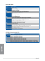
Contents
Safety information ...................................................................................................... iv
About this guide .......................................................................................................... v
ROG MAXIMUS Z790 FORMULA specifications summary ................................... viii
Package contents ..................................................................................................... xiv
Connectors with shared bandwidth ........................................................................ xv
Chapter 1: Product Introduction
1.1 Before you proceed ...................................................................................1-1
1.2 Motherboard layout ....................................................................................1-2
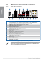
1.3 Motherboard rear and audio connections .............................................1-18
1.3.1 Rear I/O connection .................................................................. 1-18
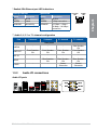
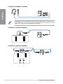
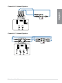
1.3.2 Audio I/O connections ............................................................... 1-19
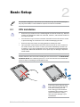
Chapter 2: Basic Setup
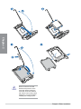
2.1 CPU installation ..........................................................................................2-1
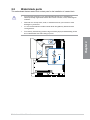
2.2 Water block ports .......................................................................................2-3
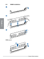
2.2 DIMM installation ........................................................................................2-4
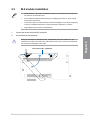
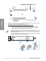
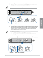
2.3 M.2 module installation ............................................................................2-5
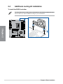
2.4 Additional cooling kit installation...........................................................2-12
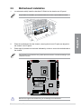
2.5 Motherboard installation .........................................................................2-13
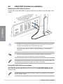
2.6 ASUS WiFi Q-Antenna installation ........................................................2-14
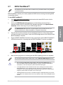
2.7 BIOS FlashBack™ ....................................................................................2-15
2.8 Starting up for the first time ....................................................................2-16
2.9 Turning off the computer ........................................................................2-16
Chapter 3: BIOS and RAID Support
3.1 Knowing UEFI BIOS ................................................................................... 3-1
3.2 ASUS EZ Flash 3 ........................................................................................3-2
3.3 ASUS CrashFree BIOS 3 ............................................................................3-3
3.4 RAID configurations ..................................................................................3-4
Appendix
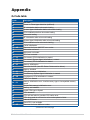
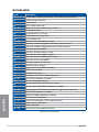
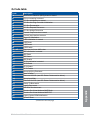
Q-Code table ............................................................................................................ A-1
General Notices ....................................................................................................... A-5
Notices for Wi-Fi model .......................................................................................... A-8
Warranty ................................................................................................................. A-16
ASUS contact information .................................................................................... A-18
Service and Support ............................................................................................. A-18

iv
Safety information
Electrical safety
• To prevent electrical shock hazard, disconnect the power cable from the electrical
outlet before relocating the system.
• When adding or removing devices to or from the system, ensure that the power cables
for the devices are unplugged before the signal cables are connected. If possible,
disconnect all power cables from the existing system before you add a device.
• Before connecting or removing signal cables from the motherboard, ensure that all
power cables are unplugged.
• Seek professional assistance before using an adapter or extension cord. These
devices could interrupt the grounding circuit.
• Ensure that your power supply is set to the correct voltage in your area. If you are not
sure about the voltage of the electrical outlet you are using, contact your local power
company.
• If the power supply is broken, do not try to fix it by yourself. Contact a qualified service
technician or your retailer.
Operation safety
• Before installing the motherboard and adding devices on it, carefully read all the
manuals that came with the package.
• Before using the product, ensure all cables are correctly connected and the power
cables are not damaged. If you detect any damage, contact your dealer immediately.
• To avoid short circuits, keep paper clips, screws, and staples away from connectors,
slots, sockets and circuitry.
• Avoid dust, humidity, and temperature extremes. Do not place the product in any area
where it may become wet.
• Place the product on a stable surface.
• If you encounter technical problems with the product, contact a qualified service
technician or your retailer.
• Your motherboard should only be used in environments with ambient temperatures
between 10°C and 35°C.
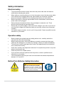
Button/Coin Batteries Safety Information
WARNING
KEEP OUT OF REACH OF CHILDREN
Swallowing can lead to chemical burns,
perforation of soft tissue, and death. Severe
burns can occur within 2 hours of ingestion.
Seek medical attention immediately.

v
About this guide
This user guide contains the information you need when installing and configuring the
motherboard.
How this guide is organized
This guide contains the following parts:
• Chapter 1: Product Introduction
This chapter describes the features of the motherboard and includes descriptions for
each part of the motherboard.
• Chapter 2: Basic Setup
This chapter lists the basic setup procedures for setting up your motherboard.
• Chapter 3: BIOS and RAID Support
This chapter tells how to boot into the BIOS, upgrade BIOS using the EZ Flash Utility
and support on RAID.
Where to find more information
Refer to the following sources for additional information and for product and software
updates.
1. ASUS website
The ASUS website (www.asus.com) provides updated information on ASUS hardware
and software products.
2. Optional documentation
Your product package may include optional documentation, such as warranty flyers,
that may have been added by your dealer. These documents are not part of the
standard package.
3. MyASUS
MyASUS offers a variety of support features such as helping to troubleshoot issues,
optimizing product performance, integrating ASUS software, and recovery drive
creation. Please visit https://www.asus.com/support for installation guide and FAQ.
MyASUS is only available on selected models, please check your motherboard’s
specifications summary to see if your motherboard supports MyASUS.

vi
6. RAID Configuration Guide
Please visit https://www.asus.com/support for more information on the RAID
Configuration Guide.
7. BIOS FlashBack™ Feature
Please visit https://www.asus.com/support for more information on the BIOS
FlashBack™ Feature.
4. Motherboard Installation Guide
Please visit https://www.asus.com/support for more information on the Motherboard
Installation Guide.
5. Driver and Utilities FAQ
Please visit https://www.asus.com/support for more information on downloading and
installing drivers and utilities for your motherboard.

vii
Conventions used in this guide
To ensure that you perform certain tasks properly, take note of the following symbols used
throughout this user guide.
CAUTION: Information to prevent damage to the components and injuries to
yourself when trying to complete a task.
IMPORTANT: Instructions that you MUST follow to complete a task.
NOTE: Tips and additional information to help you complete a task.

viii
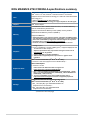
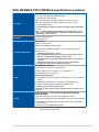
ROG MAXIMUS Z790 FORMULA specifications summary
CPU
Intel® Socket LGA1700 for Intel® Core™ 14th & 13th Gen Processors,
Intel® Core™ 12th Gen, Pentium® Gold and Celeron® Processors
Supports Intel® Turbo Boost Technology 2.0 and Intel® Turbo Boost Max
Technology 3.0**
* Refer to www.asus.com for CPU support list.
** Intel® Turbo Boost Max Technology 3.0 support depends on the CPU types.
Chipset Intel® Z790 Chipset
Memory
4 x DIMM slots, Max. 192GB, DDR5 Non-ECC, Un-buffered Memory*
Dual Channel Memory Architecture
Supports Intel® Extreme Memory Profile (XMP) memory module
ASUS Enhanced Memory Profile II (AEMP II)
Supports DIMM Flex
* Supported memory types, data rate (speed), and number of DRAM modules
vary depending on the CPU and memory configuration, for more information
please refer to CPU/Memory Support list under the Support tab of product
information site or visit https://www.asus.com/support/.
* Non-ECC, Un-buffered DDR5 Memory supports On-Die ECC function.
Graphics
1 x HDMI™ port**
2 x Intel® Thunderbolt™ 4 ports (USB Type-C®) support DisplayPort and
Thunderbolt™ video outputs***
* Graphics specifications may vary between CPU types. Please refer to
www.intel.com for any updates.
** Support 4K@60Hz as specified in HDMI 2.1.
*** VGA resolution support depends on processors’ or graphic cards’
resolution.
Expansion Slots
Intel® Core™ Processors (14th & 13th & 12th Gen)*
2 x PCIe 5.0 x16 slots (supports x16 or x8/x8 modes)**
Intel® Z790 Chipset
1 x PCIe 4.0 x4 slot
* Please check PCIe bifurcation table on support site
(https://www.asus.com/support/FAQ/1037507/).
** M.2_1 shares bandwidth with PCIEX16(G5)_2 and PCIEX16(G5)_1. When
M.2_1 is occupied with SSD device, PCIEX16(G5)_2 will be disabled and
PCIEX16(G5)_1 will run x8 only.
*** To ensure compatibility of the device installed, please refer to
https://www.asus.com/support/ for the list of supported peripherals.
Storage
Supports 5 x M.2 slots and 4 x SATA 6Gb/s ports*
Intel® Core™ Processors (14th & 13th & 12th Gen)
- M.2_1 slot (Key M), type 2242/2260/2280/22110
(supports PCIe 5.0 x4 mode)**
- M.2_2 slot (Key M), type 2242/2260/2280
(supports PCIe 4.0 x4 mode)
(continued on the next page)

ix
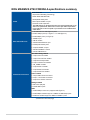
ROG MAXIMUS Z790 FORMULA specifications summary
Storage
Intel® Z790 Chipset
- M.2_3 slot (Key M), type 2242/2260/2280
(supports PCIe 4.0 x4 mode)
- M.2_4 slot (Key M), type 2280 (supports PCIe 4.0 x4 mode)
- M.2_5 slot (Key M), type 2280 (supports PCIe 4.0 x4 mode)
- 4 x SATA 6Gb/s ports
* Intel® Rapid Storage Technology supports PCIe RAID 0/1/5/10, SATA RAID
0/1/5/10.
** M.2_1 shares bandwidth with PCIEX16(G5)_2 and PCIEX16(G5)_1. When
M.2_1 is occupied with SSD device, PCIEX16(G5)_2 will be disabled and
PCIEX16(G5)_1 will run x8 only.
Ethernet 1 x Realtek 5Gb Ethernet
ASUS LANGuard
Wireless & Bluetooth®
Intel® Wi-Fi 7*
2x2 Wi-Fi 7 (802.11be)**
Supports 2.4/5/6GHz frequency band***
Support Wi-Fi 7 320MHz bandwidth, up to 5.76Gbps transfer rate.
Bluetooth® v5.4****
* Compatible with Windows 11 or later.
** Wi-Fi 7 MLO(Multi-link Operation) full functions support will be ready in
Windows 11 2024 Platform (Windows 11 24H2) or later.
*** Wi-Fi 6GHz frequency band and bandwidth regulatory may vary between
countries.
**** The Bluetooth version may vary, please refer to the Wi-Fi module
manufacturer’s website for the latest specifications.
USB
Rear USB (Total 12 ports)
2 x Thunderbolt™ 4 ports (2 x USB Type-C®)
6 x USB 10Gbps ports (5 x Type-A + 1 x USB Type-C®)
4 x USB 5Gbps ports (4 x Type-A)
Front USB (Total 9 ports)
1 x USB 20Gbps connector (supports USB Type-C® with up to 60W PD/
QC4+)**
2 x USB 5Gbps headers support 4 additional USB 5Gbps ports
2 x USB 2.0 headers support 4 additional USB 2.0 ports
* USB Type-C® power delivery output: 5V/3A
** USB Type-C® power delivery output: 5V/9V/15V/20V max. 3A, PPS: 3.3-21V
max. 3A
Audio
ROG SupremeFX 7.1 Surround Sound High Definition Audio
CODEC ALC4082*
- Impedance sense for front and rear headphone outputs
- Supports: Jack-detection, Multi-streaming, Front Panel Jack-retasking
- High quality 120 dB SNR stereo playback output and 110 dB SNR
recording input
- Supports up to 32-Bit/384 kHz playback
(continued on the next page)

x
ROG MAXIMUS Z790 FORMULA specifications summary
Audio
Audio Features
- SupremeFX Shielding Technology
- ESS® ES9218 QUAD DAC
- Gold-plated audio jacks
- Rear optical S/PDIF out port
- Premium audio capacitors
* The LINE OUT port on the back panel does not support spatial audio. If you
wish to use spatial audio, make sure to connect your audio output device
to the audio jack on the front panel of your chassis or use a USB interface
audio device.
Back Panel I/O Ports
2 x Thunderbolt™ 4 USB Type-C® ports
6 x USB 10Gbps ports (5 x Type-A + 1 x USB Type-C®)
4 x USB 5Gbps ports (4 x Type-A)
1 x HDMI™ port
1 x Wi-Fi module
1 x Realtek 5Gb Ethernet port
5 x Gold-plated audio jacks
1 x Optical S/PDIF out port
1 x BIOS FlashBack™ button
1 x Clear CMOS button
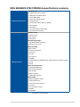
Internal I/O connectors
Fan and Cooling related
1 x 4-pin CPU Fan header
1 x 4-pin CPU OPT Fan header
1 x 4-pin AIO Pump header
4 x 4-pin Chassis Fan headers
1 x W_PUMP+ header
1 x 2-pin Water In header
1 x 2-pin Water Out header
1 x 3-pin Water Flow header
Power related
1 x 24-pin Main Power connector
2 x 8-pin +12V Power connectors
1 x 8-pin PCIe Power connector
Storage related
5 x M.2 slots (Key M)
4 x SATA 6Gb/s ports
USB
1 x USB 20Gbps connector (supports USB Type-C®)
2 x USB 5Gbps headers support 4 additional USB 5Gbps ports
2 x USB 2.0 headers support 4 additional USB 2.0 ports
(continued on the next page)

xi
ROG MAXIMUS Z790 FORMULA specifications summary
Internal I/O connectors
Miscellaneous
3 x Addressable Gen 2 headers
1 x Alteration PCIe Mode switch
1 x Aura RGB header
1 x CPU Over Voltage jumper
1 x FlexKey button
1 x Front Panel Audio header (F_AUDIO)
1 x ReTry button
1 x Start button
1 x 10⁻¹ pin System Panel header
1 x Thermal Sensor header
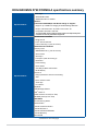
Special Features
Extreme OC Kit
- FlexKey button
- ReTry button
- Start button
Extreme Engine Digi+
- 10K Black metallic capacitors
- MicroFine alloy choke
ASUS Q-Design
- M.2 Q-Latch
- PCIe Slot Q-Release
- Q-Antenna
- Q-Code
- Q-Connector
- Q-DIMM
- Q-LED (CPU [red], DRAM [yellow], VGA [white], Boot Device [yellow
green])
- Q-Slot
ASUS Thermal Solution
- HybridChill VRM block
- M.2 heatsink backplate
- M.2 heatsink
- Metal backplate
- VRM heatsink design
ASUS EZ DIY
- BIOS FlashBack™ button
- Clear CMOS button
- CPU Socket lever protector
- ProCool II
- Pre-mounted I/O shield
- SafeSlot
- SafeDIMM
(continued on the next page)

xii
ROG MAXIMUS Z790 FORMULA specifications summary
Special Features
AURA Sync
- AURA RGB header
- Addressable Gen 2 headers
OLED 2”
Front Panel USB 20Gbps with Quick Charge 4+ Support
- Support: up to 60W fast charging and USB Wattage Watcher*
- Output: 5/9/15/20V max. 3A, PPS:3.3–21V max. 3A
- Compatible with PD3.0 and PPS
* To support 60W, please install the power cable to the 8-pin PCIe power
connector or else only 27W will be supported.
Special Features
ROG Exclusive Software
- ROG CPU-Z
- DTS® Sound Unbound
- Internet Security (1-year full version)
ASUS Exclusive Software
Armoury Crate
- AIDA64 Extreme (1 year full version)
- Aura Creator
- Aura Sync
- Fan Xpert 4 (with AI Cooling II)
- GameFirst
- Power Saving
- Sonic Studio
- Two-Way AI Noise Cancelation
- OLED display
AI Suite 3
- Easy Optimization with AI Overclocking
- TPU
- DIGI+ Power Control
- Turbo app
- PC Cleaner
MyASUS
USB Wattage Watcher
Intel® Unison™
Adobe Creative Cloud (Free Trial)
WinRAR (40 Days Free Trial)
UEFI BIOS
AI Overclocking Guide
ASUS EZ DIY
- ASUS CrashFree BIOS 3
- ASUS EZ Flash 3
- ASUS UEFI BIOS EZ Mode
- ASUS MyHotkey
MemTest86
(continued on the next page)

xiii
ROG MAXIMUS Z790 FORMULA specifications summary
BIOS 256 Mb Flash ROM, UEFI AMI BIOS
BIOS CAP Filename ROG MAXIMUS Z790 FORMULA: A5471.cap
Manageability WOL by PME, PXE
Operating System Windows® 11
Windows® 10 64-bit
Form Factor ATX Form Factor
12 inch x 9.6 inch (30.5 cm x 24.4 cm)
Specifications are subject to change without notice. Please refer to the ASUS website for
the latest specifications.

xiv
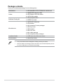
Package contents
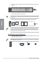
Check your motherboard package for the following items.
Motherboard 1 x ROG MAXIMUS Z790 FORMULA motherboard
Cables
1 x ARGB RGB extension cable
2 x ROG Weave SATA 6G cables
2 x SATA 6Gb/s cables
Additional Cooling Kit 1 x Thermal pad for M.2
1 x DDR5 Fan holder
Miscellaneous
1 x ASUS WiFi Q-Antenna
1 x Q-connector
3 x M.2 backplate Q-Latch packages
1 x ROG key chain
1 x ROG stickers
1 x ROG VIP card
1 x M.2 rubber package
3 x M.2 backplate rubber packages
Installation Media 1 x USB drive with utilities and drivers
Documentation 1 x Quick Start Guide
• If any of the above items is damaged or missing, contact your retailer.
• Items not listed in the Package contents list above are purchased separately and do
not come bundled with your motherboard package.

xv
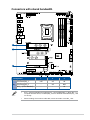
Connectors with shared bandwidth
A
A
A
Configuration 1 2 3
A
PCIEX16(G5)_1 x16 x8 x8
PCIEX16(G5)_2 - x8 N/A
M.2_1 (CPU attached) - - x4
• M.2_1 shares bandwidth with PCIEX16(G5)_2 and PCIEX16(G5)_1. When M.2_1 is
occupied with SSD device, PCIEX16(G5)_2 will be disabled and PCIEX16(G5)_1 will
run x8 only.
• When installing a PCIe Gen 5.0 M.2 SSD, ensure to install it to the M.2_1 slot.

xvi

Motherboard User Manual 1-1
Chapter 1
Product Introduction
1
Chapter 1: Product Introduction
• Unplug the power cord from the wall socket before touching any component.
• Before handling components, use a grounded wrist strap or touch a safely grounded
object or a metal object, such as the power supply case, to avoid damaging them due
to static electricity.
• Hold components by the edges to avoid touching the ICs on them.
• Whenever you uninstall any component, place it on a grounded antistatic pad or in
the bag that came with the component.
• Before you install or remove any component, ensure that the power supply is
switched off or the power cord is detached from the power supply. Failure to do so
may cause severe damage to the motherboard, peripherals, or components.
The pin definitions in this chapter are for reference only. The pin names depend on the
location of the header/jumper/connector.
1.1 Before you proceed
Take note of the following precautions before you install motherboard components or
change any motherboard settings.

1-2 Chapter 1: Product Introduction
Chapter 1
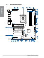
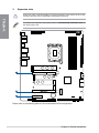
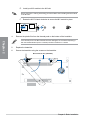
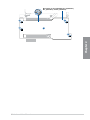
1.2 Motherboard layout
PCIEX4(G4) BATTERY
M.2_5(SOCKET3)
2280
LGA1700
M.2_3(SOCKET3)
2280
2260 2242
M.2_4(SOCKET3)
2280
LED2
LED1
DDR4 DIMM_A2* (64bit, 288-pin module)
DDR4 DIMM_A1 (64bit, 288-pin module)
DDR4 DIMM_B2* (64bit, 288-pin module)
DDR4 DIMM_B1 (64bit, 288-pin module)
HD_LED
ATX_PWR
CPU
DRAM
VGA
BOOT
T_SENSOR
U5G_E34
ALT_PCIE_MODE
CPU_OPT
CPU_FAN AIO_PUMP
PLUG_8PIN_PWR
PLD5300
F_AUDIO
SATA6G_1
SATA6G_2
SATA6G_3
SATA6G_4
Intel®
Z790
AUDIO
LAN_U10G_6
TBT4_EC2
U5G_E5678
U10G_123
U10G_C4
TBT4_EC1
U10G_5
M.2(WIFI)
USB_E12 USB_E34
U5G_E12
PCIEX16(G5)_2
PCIEX16(G5)_1
W_IN
W_OUT
U20G_C9
W_FLOW
FLBK_CL_CMOS
CHA_FAN4
CHA_FAN3
F_PANEL
CHA_FAN1 ADD GEN2_1
Q_CODE
START
RETRY_BUTTON
FLEXKEY
ADD GEN2_3
ADD GEN2_2
RGB_HEADER
CPU_12V_1 CPU_12V_2
PCIE_8PIN_PWR
CPU_OV
W_PUMP+
CHA_FAN2
2280
22602242
2242 2260 2280
22110
HDMI
M.2_1(SOCKET3)
M.2_2(SOCKET3)
16
19
18
12
23
6
9
7
7
7
7
10
8
24
21
20541213 1417 114 10
4 226 15
25
1 2
3
3

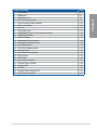
Motherboard User Manual 1-3
Chapter 1
Layout contents Page
1. CPU socket 1-4
2. DIMM slots 1-5
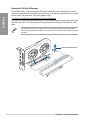
3. Expansion slots 1-6
4. Fan and Pump headers 1-9
5. Liquid Cooling System headers 1-10
6. Power connectors 1-10
7. M.2 slot 1-11
8. SATA 6Gb/s port 1-11
9. USB 20Gbps Type-C® Front Panel connector 1-12
10. USB 5Gbps header 1-12
11. USB 2.0 header 1-12
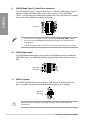
12. Addressable Gen 2 header 1-13
13. Alteration PCIe Mode switch 1-13
14. Aura RGB header 1-14
15. CPU Over Voltage jumper 1-14
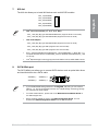
16. FlexKey button 1-14
17. Front Panel Audio header 1-15
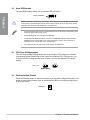
18. ReTry button 1-15
19. Start button 1-15
20. System Panel header 1-16
21. Thermal Sensor header 1-16
22. Q-Code LED 1-16
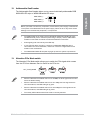
23. Q-LEDs 1-17
24. Storage Device Activity LED 1-17
25. 8-pin Power Plug LED 1-17

1-4 Chapter 1: Product Introduction
Chapter 1
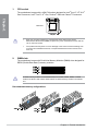
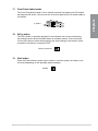
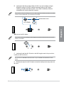
1. CPU socket
The motherboard comes with a LGA1700 socket designed for Intel® Core™ 14th & 13th
Gen Processors, Intel® Core™ 12th Gen, Pentium® Gold and Celeron® Processors.
LGA1700
• Keep the cap after installing the motherboard. ASUS will process Return
Merchandise Authorization (RMA) requests only if the motherboard comes with the
cap on the CPU socket.
• The product warranty does not cover damage to the socket contacts resulting from
incorrect CPU installation/removal, or misplacement/loss/incorrect removal of the
PnP cap.
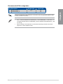
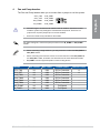
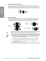
2. DIMM slots
The motherboard comes with Dual Inline Memory Modules (DIMM) slots designed for
DDR5 (Double Data Rate 5) memory modules.
A DDR5 memory module is notched differently from a DDR, DDR2, DDR3, or DDR4
module. DO NOT install a DDR, DDR2, DDR3, or DDR4 memory module to the DDR5
slot.
Recommended memory configurations
La page charge ...
La page charge ...
La page charge ...
La page charge ...
La page charge ...
La page charge ...
La page charge ...
La page charge ...
La page charge ...
La page charge ...
La page charge ...
La page charge ...
La page charge ...
La page charge ...
La page charge ...
La page charge ...
La page charge ...
La page charge ...
La page charge ...
La page charge ...
La page charge ...
La page charge ...
La page charge ...
La page charge ...
La page charge ...
La page charge ...
La page charge ...
La page charge ...
La page charge ...
La page charge ...
La page charge ...
La page charge ...
La page charge ...
La page charge ...
La page charge ...
La page charge ...
La page charge ...
La page charge ...
La page charge ...
La page charge ...
La page charge ...
La page charge ...
La page charge ...
La page charge ...
La page charge ...
La page charge ...
La page charge ...
La page charge ...
La page charge ...
La page charge ...
La page charge ...
La page charge ...
La page charge ...
La page charge ...
La page charge ...
La page charge ...
-
 1
1
-
 2
2
-
 3
3
-
 4
4
-
 5
5
-
 6
6
-
 7
7
-
 8
8
-
 9
9
-
 10
10
-
 11
11
-
 12
12
-
 13
13
-
 14
14
-
 15
15
-
 16
16
-
 17
17
-
 18
18
-
 19
19
-
 20
20
-
 21
21
-
 22
22
-
 23
23
-
 24
24
-
 25
25
-
 26
26
-
 27
27
-
 28
28
-
 29
29
-
 30
30
-
 31
31
-
 32
32
-
 33
33
-
 34
34
-
 35
35
-
 36
36
-
 37
37
-
 38
38
-
 39
39
-
 40
40
-
 41
41
-
 42
42
-
 43
43
-
 44
44
-
 45
45
-
 46
46
-
 47
47
-
 48
48
-
 49
49
-
 50
50
-
 51
51
-
 52
52
-
 53
53
-
 54
54
-
 55
55
-
 56
56
-
 57
57
-
 58
58
-
 59
59
-
 60
60
-
 61
61
-
 62
62
-
 63
63
-
 64
64
-
 65
65
-
 66
66
-
 67
67
-
 68
68
-
 69
69
-
 70
70
-
 71
71
-
 72
72
-
 73
73
-
 74
74
-
 75
75
-
 76
76


Asus ROG MAXIMUS Z790 FORMULA Manuel utilisateur
- Catégorie
- Cartes mères
- Taper
- Manuel utilisateur
dans d''autres langues
Documents connexes
-
Asus ROG MAXIMUS Z790 DARK HERO Manuel utilisateur
-
-
-
-
-
-
-
-
-