La page est en cours de chargement...

SERIES 19HE BOILER
INSTALLATION
INSTRUCTIONS
STEAM OR WATER HEATING
PRESSURIZED FOR FIRING OIL, GAS
OR COMBINATION GAS/OIL
CAUTION: Do not use automotive anti-freeze in boiler waterways. If necessary to
use anti-freeze, be sure to employ a preparation designed for hydronic heating
systems such as ethylene or propylene glycol.
Water treatment is not recommended. This boiler uses gaskets to seal the ports
of adjoining sections. These gaskets are made of a uorocarbon elastomer
(designation FKM) marketed under the brand name Viton. Consult a water
treatment professional before adding any chemical to the boiler water. Any
water treatment or anti-freeze added to the system must be compatible with the
Viton gaskets.
THE SECTIONS OF THIS BOILER MUST BE ASSEMBLED
TO THE PROPER TORQUE. READ INSTRUCTIONS
19IOM-8R
82-7011
4/2022
TO INSTALLER
NOTE: READ THESE INSTRUCTIONS CAREFULLY. THEY WILL
SAVE YOU VALUABLE TIME WHEN ASSEMBLING THE BOILER.
DESIGNED AND TESTED ACCORDING TO THE A.S.M.E. BOILER AND PRESSURE
VESSEL CODE, SECTION IV FOR MAXIMUM ALLOWABLE WORKING PRESSURE.
STEAM - 15 PSIG, WATER - 80 PSIG
INSTALLER, THESE INSTRUCTIONS TO BE AFFIXED ADJACENT TO THE BOILER.
CONSUMER, RETAIN THESE INSTRUCTIONS FOR FUTURE REFERENCE PURPOSES.
FOR JACKET ASSEMBLY AND BURNER SET UP SEE SEPARATE INSTRUCTIONS.
TEL. (413) 562-9631 FAX (413) 562-3799

2
SERIES 19HE BOILER
INSTALLATION INSTRUCTIONS
10 in. Smokehood Assy. 70341
(8-12 Sect. 19 & 19A)
4A Smokehood Tape 74300
5 Slide Damper Only 69370
6 Angle Bracket Only 69150
7 Tankless Cover Plate Assy 70343
(includes Studs, Nuts & Gasket)
— Tankless Cover Plate Stud 60104
— Tankless Cover Plate Nut 60874
8 Tankless Cover Plate Gasket 60312
8A Tankless Coil 50634
w/Gasket and Hardware
SERIES 19HE REPLACEMENT PARTS
Ref # Name of Part Part No. Ref # Name of Part Part No.
1 Front Section 3638
2 Plain Leg Section 3637
Heater Leg Section 3641
3 Back Section 3639
Smokehood Assembly includes:
Smokehood, Slide Damper, Angle Bracket, and Hardware
4 7 in. Smokehood Assy. 70338
(3-5 Sect. for 19) (3-4 for 19A)
8 in. Smokehood Assy. 70339
(6 Sect. for 19) (5-6 Sect. for 19A)
9 in. Smokehood Assy. 70340
(7 Sect. 19 & 19A)

3
Ref # Name of Part Part No. Ref # Name of Part Part No.
SERIES 19HE REPLACEMENT PARTS
19HE
Cleanout Cover Assembly includes:
Cleanout Plate, Insulation, Rope and Hardware
9 Clean Out Cover Plate Assy 70590
— Rope Seal (45 in.) 76538
— Silicone Sealant 10.3oz 61924
10/11/12 C/O Cover Hardware Kit 21-1502
Burner Mounting Plate Assembly includes:
Mounting Plate with Observation Glass and Cover
13 Burner Mounting Plate Assy 70465
6-1/8 in. Opening
Burner Mounting Plate Assy 70466
7-3/4 in. Opening
Burner Mounting Plate Assy 70491
9-1/8 in. Opening
— Burner Mounting Plate H'ware 71316
14 Observation Glass Only 60326
15 Observation Glass Gasket 60317
16 Observation Glass Gasket 60318
17 Observation Glass Holder 60314
— Screws, Observation Glass 61757
18 Observation Cover Plate 3420
19 Rope Seal 1/4 in. x 4.75 ft. 78105
20 Burner Insulating Block 60434
Burner Insulating Block 60430
(3-6 Sect. – Beckett)
— Burner Insulating Block H'ware 71268
21 Upper Port Gasket (Viton) 60339
1 per Section
22 Lower Port Gasket (Viton) 60340
1 per Section
23 Target Wall (3-6 Sect. only) 69761
24 5/8 in. x 9 in. Draw Rod 60101
25 5/8 in. Hex Nut 60877
26 5/8 in. Washer 62099
– Flue Brush 60090
27 3/8 in. Rope (10 ft. 4 in. per sect.) 78100
– Spray Adhesive 70492
28 Rear Observation Port Cover 3679
(3-6 Section)
29 Rear Observation Port Assy 70614
(7-12 Section)
— Rear Observation Port H'ware 71301
Steam Trim and Controls
30 3-1/2 in. Steam Gauge 60269
31 Gauge Glass 5/8 in. x 9-7/8 in. 61862
32 1 in. Steam Relief Valve 61982
(3-5 Sect. on 19 & 19A)
1-1/4 in. Steam Relief Valve 61983
(6-10 Sect. on 19) (6-8 Sect. on 19A)
1-1/2 in. Steam Relief Valve 61984
(11-12 Sect. on 19) (9-12 Sect. on 19A)
33 PA404A Operating Control 50493
34 L4079B Limit Control 50495
Water Trim and Controls
35 3-1/2 in. Theraltimeter 60290
36 3/4 in. Relief Valve 61997
(3-10 Sect. on 19) (3-8 Sect. on 19A)
1 in. Relief Valve 61998
(11-12 Sect. on 19) (9-11 Sect. on 19A)
1-1/4 in. Relief Valve (19A-12) 61999
37 L4006A Operating Control 50511
38 L4006E Limit Control 14-1001

4
CODES AND REGULATIONS
All work in connection with the boiler, burner and controls
must be performed in strict accordance with requirements
of state and local authorities having jurisdiction over boiler
installations.
Figure 1
In the absence of such local requirements, the following
should govern:
A.S.M.E. Section IV - “Heating Boilers"
A.S.M.E. Section VI - “Care and Operation of Boilers”
ANSI/NFPA 31 - “Installation of Oil Burning Equipment”
ANSI/Z223.1 - “National Fuel Gas Code”
ANSI/NFPA 70 - “National Electrical Code”
SERIES 19HE BOILER
INSTALLATION INSTRUCTIONS
CONTENTS
Series 19HE Exploded View
.............................................page 2
Parts List.......................................................................page 2
Table of Contents..........................................................page 4
General Information ...................................................... page 4
Boiler Location .............................................................. page 4
Codes and Regulations ................................................page 4
Combustion Air and Ventilation.....................................page 5
Chimney and Vent Pipe Connections .......................... page 5
Common Vent Systems ................................................ page7
Assembly of Sections ...................................................page 9
Hydrostatic Test ..........................................................page 10
Steam Piping ..............................................................page 10
Water Piping .............................................................. page 11
Tankless Heaters ........................................................ page 11
Smokehood ................................................................page 11
Burner Mounting Plate ................................................ page 12
Cleanout Covers ......................................................... page 13
Rear Observation Port ................................................ page 13
Control Locations........................................................page 13
Jacket .........................................................................page 13
Safety and Relief Valves ............................................ page 13
Cleaning Boiler Waterways ........................................page 14
Start Up and Maintenance Instructions ......................page 14
Control Tappings Diagram ..........................................page 15
Warning ......................................................................page 16
GENERAL INFORMATION
Series 19HE boilers are wet-base, extended surface, vertical
ue design with integral cast ue gas collector for pressurized
ring with oil, gas or combination power burners. Upper and
lower port hydronic seals are of a special material resistant to
petroleum products and compatible with ethylene and
propylene based anti-freeze (non automotive type) which does
not contain corrosion inhibitors to protect aluminum. The ue
gas joints between sections, etc. are sealed using high
temperature (2300°F) ceramic fiber rope. Access to the
heating surface for cleaning is provided from the left hand side
of the boiler through large cast iron cover plates. A slide
damper is provided in the ue gas outlet for back pressure
adjustment.
The boilers are supplied completely knocked down for eld
assembly, as factory assembled blocks of sections or
completely packaged boiler-burner units. All items should be
inspected for damage upon receipt, and any damage reported
to the wholesaler and trucker. All components should be stored
in a clean, dry area.
The boilers are conservatively rated for high efciency
performance with capability for down-ring to match connected
load. The large OBROUND upper port provides transfer area
above the water surface for dry steaming at full load.
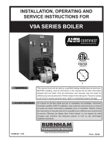
BOILER LOCATION
The boiler must be installed on a smooth, level, non-
combustible floor or pad as close to the chimney or vent
location as possible to minimize breeching length. Allow
clearance around the boiler for piping, service, maintenance,
cleaning and tankless coil removal. Approximately 30 inches
on the sides is a minimum (Check local code requirements).
Do not install electrical conductors in oor or pad under boilers.
See Figure 1 for boiler oor pad requirements, and Table 1 for
minimum required pad length.
Boiler No. Min. Recommended Pad Length
19HE-3 30"
19HE-4 36"
19HE-5 42"
19HE-6 48"
19HE-7 54"
19HE-8 60"
19HE-9 66"
19HE-10 72"
19HE-11 78"
19HE-12 84"
Table 1
4 5/32" 12 27/32" 12 27/32"
25 21/32"
4 5/32"
34"
32"
JACKET SIDE PANEL
C
LOF BOILER
FLOOR
OR PAD
1 1/2" x 2 1/2" ANGLES

5
COMBUSTION AND VENTILATION AIR
WARNING: This boiler must be supplied with
combustion and ventilation air in accordance with the
latest revision of Section 9.3, Air for Combustion &
Ventilation, of the National Fuel Gas Code, ANSI Z223.1/
NFPA 54 for gas boilers or ANSI/NFPA 31 Installation of
Oil Burning Equipment for oil boilers. Canadian
installations must comply with CAN/CSA B149.1 Natural
Gas and Propane Installation Code for gas boilers or
CSA B140.7 Oil Burning Equipment for oil boilers. All
applicable local building codes must be adhered to.
Failure to provide adequate combustion air for this
boiler can result in excessive levels of carbon monoxide
which can result in severe personal injury or death!
To operate properly and safely this boiler requires a
continuous supply of air for combustion. An adequate supply of
air must be available to replace the air used by the combustion
process. NEVER store objects on or around the boiler.
CAUTION: Never use an exhaust fan in the boiler room.
The boiler room must never be under a negative pressure
or improper burner operation will occur!
NOTE: If mechanical combustion air supply is required,
the system must be approved by the local authorities,
and should provide at least 30 CFM per gallon of oil and
.35 CFM/1,000 BTU HR (.034 m3/min per kw) of gas input
to the boilers.
All Air From Inside The Buidling
If the boiler is to be located in a conned space minimum
clearances of 24 in., 610 mm must be maintained between
the boiler and any adjacent construction. When installed in a
conned space, two permanent openings communicating with
an additional room(s) are required. The combined volume of
these spaces must have sufcient volume to meet the criteria
for an unconned space. The total air requirements of all
fuel burning equipment or any type of exhaust fan must be
considered when making this determination.
Each opening must have a minimum free area of 1 in2/1000
Btu/hr, 140 in2/GPH, 2200 mm2/kW based on the total input
rating of ALL fuel burning equipment in the conned area.
Each opening must be no less than 100 in2, 64,516 mm2 in
size. The upper opening must be within 12 in., 305 mm of,
but not less than 3 in., 76 mm from, the top of the enclosure.
The bottom opening must be within 12 in., 305 mm of, but
not less than 3 in., 76 mm from, the bottom of the enclosure.
All Air From Outside The Building
When installed in a conned space two permanent openings
communicating directly with, or by ducts to, the outdoors or
spaces that freely communicate with the outdoors must be
present. The upper opening must be within 12 in., 305 mm of,
but not less than 3 in., 76 mm from, the top of the enclosure.
The bottom opening must be within 12 in., 305 mm of, but not
less than 3 in., 76 mm from, the bottom of the enclosure.
SERIES 19HE BOILER
INSTALLATION INSTRUCTIONS
Where directly communicating with the outdoors or
communicating with the outdoors through vertical ducts, each
opening shall have a minimum free area of 1 in2/4000 Btu/hr,
35 in2/GPH, 550 mm2/kW of the total input rating of all of the
equipment in the enclosure.
Where communicating with the outdoors through horizontal
ducts, each opening shall have a minimum free area of 1
in2/2000 Btu/hr, 70 in2/GPH, 1100 mm2/ kW of the total input
rating of all of the equipment in the enclosure. When ducts
are used, they must have the same cross-sectional area as
the free area of the opening to which they connect. When
calculating the free area necessary to meet the make-up air
requirements of the enclosure, consideration must be given
to the blockage effects of louvers, grills and screens. Screens
must have a minimum mesh size of 1/4 in, 6.4mm. If the free
area through a louver or grill is not known the louver or grille
should be sized per Table 1.
Table 1 - Make-up Air Louver Sizing
Required Cross Sectional Louver Area (in2)
Ventilation air, if required, must be in addition to the
combustion air quantities called for above.
CHIMNEY & VENT PIPE CONNECTIONS
WARNING: The vent installation must be in
accordance with the latest revision of Part 7, Venting
of Equipment, of the National Fuel Gas Code, ANSI
Z223.1/NFPA 54 for gas boilers or ANSI/NFPA 31
Installation of Oil Burning Equipment for oil boilers
and the ASHRAE Equipment Handbook on Venting.
Canadian installations must comply with CAN/CSA
B149.1 Natural Gas and Propane Installation Code for
gas boilers or CSA B140.7 Oil Burning Equipment for
oil boilers. All applicable local building codes must be
adhered to. Improper venting of this boiler can result
in excessive levels of carbon monoxide which can
result in severe personal injury or death!
CAUTION: The products of combustion from a 19HE
must be safely vented to the outdoors while ensuring
that the ue gases do not cool prematurely. It's critical
that the chimney system be properly designed to handle
the relatively cool ue gas temperatures. An oversized or
uninsulated chimney will cause the moisture in the ue
gases to condense resulting in damage to the chimney
system unless it's specically designed for condensate. If
this is the case a suitable condensate drain must be used
to protect the boiler from condensate.
NOTE: Our warranty does not cover corrosion damage to
the boiler or its vent system caused by ue gas condensate!
Input
(MBH)
1/4", 6.4 mm
Wire Screen
Metal Louvers
75% Free Area
Wooden Louvers
25% Free Area
in2cm2in2cm2in2cm2
400 100 645 133 860 400 2581
600 150 968 200 1289 600 3871
800 200 1290 266 1720 800 5162
1000 250 1613 333 2148 1000 6452
1200 300 1936 400 2578 1200 7742
1400 350 2258 467 3007 1400 9033
1600 400 2581 533 3437 1600 10,323
1800 450 2903 600 3866 1800 11,614
2000 500 3226 666 4296 2000 12,904

6
SERIES 19HE BOILER
INSTALLATION INSTRUCTIONS
Chimney Inspection & Sizing
If this boiler will be connected to a masonry chimney, a
thorough inspection of the chimney must be performed.
Ensure that the chimney is clean, properly constructed, lined
and properly sized, see Figure 2. Table 2 lists the equivalent
breeching and ue sizes required for the 19HE boilers.
Table 2 - Equivalent Breeching & Chimney Size
Note: These sizes are based on a 20 foot chimney height.
The 19HE Series is designed for pressurized operation with a
maximum back pressure of 0.10 in., 2.54 mm WC before the
smoke hood slide damper. If the vent conguration results in a
maximum back pressure greater than this, the burner capacity
may have to be reduced. Contact the Smith Technical Service
Department to verify the burner capacity.
The chimney must be able to provide 0.10 in. WC at the
boiler outlet. If the chimney is 50 ft. or taller it may produce
excessive draft (appox. - 0.25 in. WC) and a barometric draft
regulator may be needed.
Boiler Size Breeching Size Chimney Size
in mm in mm
19HE-3 7 178 7 178
19HE-4 7 178 7 178
19HE-5 8 203 8 203
19HE-6 8 203 8 203
19HE-7 9 229 9 229
19HE-8 10 254 10 254
19HE-9 10 254 10 254
19HE-10 10 254 10 254
19HE-11 12 305 12 305
19HE-12 12 305 12 305
When more than one piece of combustion equipment is
connected to the same chimney ue, the ue must be
large enough to safely vent the combined output of all the
equipment.
WARNING: If an appliance using any type of a
mechanical draft system operating under positive
pressure is connected to a chimney flue, never
connect a Category I appliance to this ue. Doing so
can result in the accumulation of carbon monoxide
which can cause severe personal injury or death!
The breeching connection between boiler and chimney should
be as direct as possible with the minimum number of elbows
or bends. It should pitch upwards to the chimney at a rate of
1/4 inch per foot of horizontal run. Generally, the breeching
and chimney should be the same diameter as the boiler outlet
connection.
NOTE: 11 and 12 section uses adapter collar for
connection to 12 in. diameter vent system. Transition
collar provided by Smith.
For fuel conservation and stable burner performance, the vent
connection from the boiler should not include a barometric
draft control or other opening unless the venting system can
develop an excessive draft, or is required by code.
Typically stack heights less than 50 ft will not require the use
of a barometric damper.
Figure 2- Vertical Venting

7
SERIES 19HE BOILER
INSTALLATION INSTRUCTIONS
VENT CONNECTIONS
WARNING: Never modify or alter any part of the boiler’s
smoke hood. This includes the removal or alteration of
any baffles. Never install a vent pipe of a diameter
smaller than that of the boiler smoke hood outlet.
Failure to comply with this warning can result in severe
personal injury or death.
Locate the boiler as close to the chimney as possible. Use
the shortest, straightest vent connector possible for the
installation. If horizontal runs exceed 5 ft., 1.5 m they must
be supported at 3 ft., 0.9 m intervals with overhead hangers.
Use a single wall stainless or single wall galvanized steel
vent pipe the same diameter as the ue collar to connect the
boiler to a masonry chimney. When using an approved metal
chimney system use the appropriate vent connector. The
vent connector should be sloped up toward the chimney at a
minimum rate of 1/4 in/ft, 2 cm/m. On masonry chimneys the
connector must terminate ush with the inside of the chimney
ue Fasten each single wall vent connection with at least 3
corrosion resistant sheet metal screws.
The vent materials used in positive pressure vent systems
must be certied to UL 1738 for installations in the
United States, ULS636 for installations in Canada. The
following manufactures have systems that meet these
requirements:
Heat-Fab, Inc.
38 Hayward Street
Greeneld, MA 01301, (800) 772-0739.
Z-Flex U.S., Inc.
20 Commerce Park
North, Bedford, NH 03110-6911, (800) 654-5600.
Protech Systems Inc.
26 Gansevoort Street
Albany, NY 12202 (518) 463-7284
WARNING: Breeching under positive pressure must be
certied to UL 1738 for installations in the United States,
ULS636 for installations in Canada. Type B1 vent SHALL
NOT be used. Failure to comply with this warning can
result in severe personal injury or death.
Always provide a minimum clearance of 6 in., 152 mm
between single wall metal vent pipe and all combustible
materials.
WARNING: Failure to maintain minimum clearances
between vent connectors and any combustible material
can result in a re causing extensive property damage,
severe personal injury or death!
COMMON VENT SYSTEMS
If an existing boiler is removed from a common venting
system, the common venting system may then be too
large for the proper venting of the remaining appliances
connected to it. At the time of removal of an existing boiler,
the following steps shall be followed with each appliance
remaining connected to the common venting system
placed in operation, while the other appliances remaining
connected to the common venting system are not in
operation.
Au moment du retrait d'une chaudière existante, les
mesures suivantes doivent être prises pour chaque appareil
toujours raccordé au système d'évacuation commun et qui
fonctionne alors que d'autres appareils toujours raccordés
au système d'évacuation ne fonctionnent pas: système
d'évacuation
a) Seal any unused openings in the common venting
system. Sceller toutes les ouvertures non utilisées du
système d'évacuation.
b) Visually inspect the venting system for proper size and
horizontal pitch and determine there is no blockage or
restriction, leakage, corrosion and other deciencies
which could cause an unsafe condition.
Inspecter de façon visuelle le système d'évacuation
pour déterminer la grosser et l'inclinaison horizontale
qui conviennent et s'assurer que le système est exempt
d'obstruction, d'étranglement de fruite, de corrosion et
autres défaillances qui pourraient présenter des risques.
c) Insofar as is practical, close all building doors and
windows and all doors between the space in which the
appliances remaining connected to the common venting
system are located and other spaces of the building.
Turn on clothes dryers and any appliance not connected
to the common venting system. Turn on any exhaust
fans, such as range hoods and bathroom exhaust, so
they will operate at maximum speed. Do not operate
a summer exhaust fan for a boiler installation. Close
replace dampers.
Dans la mesure du possible, fermer toutes les portes
et les fenêtres du bâtiment et toutes les portes entre
l'espace où les appareils toujours raccordés du système
d'évacuation sont installés et les autres espaces du
bâtiment. Mettre en marche les sécheuses, tous les
appareils non raccordés au système d'évacuation
commun et tous les ventilateurs d'extraction comme les
hottes de cuisinère et les ventilateurs des salles de bain.
S'assurer que ces ventilateurs fonctionnent à la vitesse
maximale. Ne pas faire fonctionner les ventilateurs d'été.
Fermer les registres des cheminées.

8
SERIES 19HE BOILER
INSTALLATION INSTRUCTIONS
d) Place in operation the appliance being inspected. Follow
the lighting instructions. Adjust thermostat so appliance
will operate continuously. Mettre l'appareil inspecté en
marche. Suivre les instructions d'allumage. Régler le
thermostat de façon que l'appareil fonctionne de façon
continue.
e) Test for spillage at the draft hood relief opening after
5 minutes of main burner operation. Use the ‡ame of
a match or candle, or smoke from a cigarette, cigar or
pipe.
Faire fonctionner le brûleur principal pendant 5
min ensuite, déterminer si le coupetirage déborde
à l'ouverture de décharge. Utiliser la ‡amme d'une
allunette ou d'une chandelle ou la fumée d'une cigarette,
d'un cigare ou d'une pipe.
f) After it has been determined that each appliance
remaining connected to the common venting system
properly vents when tested as outlined above, return
doors, windows, exhaust fans, replace dampers and
any other gas-burning appliance to their previous
condition of use.
Une fois qu'il a été d éterminé, selon la métode indiquée
cidessus, que chaque appareil raccordé au système
d'évacuation est mis à l'air libre de façor adéquate.
Remettre les portes et les fenêtres, les ventilateurs, les
registres de cheminées et les appareils au gaz à leur
position originale.
g) Any improper operation of the venting system should be
corrected so the installation conforms with the National
Fuel Gas Code, ANSI Z223.1/ NFPA 54 or ANSI/NFPA
31 Installation of Oil Burning Equipment for oil burners.
When resizing any portion of the common venting
system, the common venting system should be resized
to approach the minimum size as determined using the
appropriate tables in Appendix F in the National Fuel
Gas Code, ANSI Z223.1/NFPA 54 and or CSA B149
Installation Codes.
Tout mauvais fonctionnement du systéme d'évacution
commun devrait étré corrigé de façor que l'installation
soit conforme au National Fue Gas Code, ANSI Z223.1/
NFPA 54 et (ou) aux codes d'installation CAN/CGA-B149
or ANSI/NFPA 31 Installation of Oil Burning Equipment
for oil burners. Si la grosseur d'une section du système
d' évacuation doit étré modiée, le système devrait
étré modié pour respecter les valeurs minimales des
tableaux pertinents de l'appendice F du National Fuel
Gas Code, ANSI Z223.1/NFPA 54 et (ou) des codes
d'installation CSA-B149.

9
CAUTION: Do not spray adhesive into the hydronic seal
ports.
Apply a length of wicking avoiding bends and twists. Be sure
ends extend past the cleanout cover opening. (See Figure 2)
Place the upper and lower hydronic seals in the recessed
section taking care not to dislodge the rope or the hydronic
seals. Inspect the alignment of the sections through the open
ports and, if properly aligned, install the draw rods with nuts
drawn hand-tight. (See Figure 3) Plumb the sections before
applying torque to the upper right and lower left draw rods.
Maintain nger-tight torque on upper left and lower right draw
rods.
Figure 2
IMPORTANT
The upper and lower ports should be drawn up metal to
metal around the outside of the hydronic seal. Metal to
metal conditions will not occur at any other location.
Avoid excessive torque on upper left and lower right
draw rods, which may warp the section. See Figure 3 for
correct alignment of the seal.
Assemble additional sections as described above.
After draw rods are hand tight, torque as shown in Table 3.
Use anti-seize on draw rod and washer, coating thread and
washer on one end only. Torque the draw rods from the end
with anti-seize and washer. Follow the steps as described below.
Do not completely tighten one side; gradually work each side
using an alternating pattern until the correct torque is reached.
ASSEMBLY OF SECTIONS
When boilers are delivered to the job site, each item should
be inspected closely for possible shipping damage. Scars or
nicks in the port sealing surfaces may allow leakage. Do not
attempt to use any section that has been damaged in the
port seal area.
When ready to commence assembly, recommended on a level
pad, place the angle rails in position parallel with each other
with the 2 in. legs on the oor and measuring 25-21/32 inches
outside dimension. Be sure to align the center of the boiler
with the center line of the pad. If no pad is provided, shim and
grout under the angles to make them level and provide support
along the full length. (See Figure 1) Clean hydronic gasket
recesses and rope groove with a wire brush, taking care not
to damage machine surface.
See Table 2 for proper location of sections.
Table 2 - Section Locations
F = Front Section
P = Plain intermediate section
H = Heater intermediate section-Optional, must be ordered.
If not required change to P.
B = Back Section
CAUTION: Due to the fact that the sections are top
heavy, it is absolutely necessary that the back section be
supported in such a manner as to prevent its falling and
causing potential serious bodily injury while preparing
to add the next section. One such way would be to insert
a piece of 3 in. x 36 in. piping in the lower port.
NOTE: Some sections may need shims under support
feet to align with other sections.
Stand the back section in place with the feet on and in the
angle iron rails. Support the section as required to prevent it
from falling forward or rearward. Clean hydronic gasket
recesses and rope groove with a stiff wire brush. Apply
spray-on adhesive (supplied with the boiler) to rope groove
to hold wicking in place during assembly.
SERIES 19HE BOILER
INSTALLATION INSTRUCTIONS
3 SECT
4 SECT
5 SECT
6 SECT
7 SECT
8 SECT
9 SECT
10 SECT
11 SECT
12 SECT
F
F
F
F
F
F
F
F
F
F
H
P
H
P
H
P
P
P
P
P
B
H
P
H
P
H
H
P
P
P
B
H
P
H
P
P
H
P
P
B
H
P
H
H
P
H
P
B
H
P
P
H
P
H
B
H
H
P
H
P
B
P
H
P
H
B
P
H
P
B
P
H
B
PB
HEATING
SURFACE
CLEANOUT CO
VER
LOWER PORT
UPPER PORT
CERAMIC ROPE
JOINT SEAL
FLOOR
SECTIONAL VIEW

10
2. Water Boilers – The assembled boiler shall be subjected
to a hydrostatic test pressure not less than 1-1/2 times the
maximum allowable working pressure (81.5 PSIG).
3. The required test shall not exceed the test pressure by
more than 10 PSI.
Excessive torque on draw rods may damage castings. Do not
exceed the torque shown in Table 3.
In a cold environment, hydronic seals may not quickly conform
to sealing surfaces when properly compressed. Under such
conditions, hydrostatic testing with cold water might show
weeping or leaking at the seals. To avoid this possibility, delay
lling the boiler with cold water for a few hours after assembly,
or use warm water, if available, for the tests.
If there is seepage about chaplets or minor leakage, consult
the Smith Company representative for advice regarding
A.S.M.E. Code approved repairs by peening or plugging.
STEAM PIPING
A steam piping schedule is shown in Table 4. Pitch piping to
allow condensate to flow in the same direction as steam.
Makeup water connections must be made to the return piping,
not directly to the boiler. Install blow-down valves as required.
See Figure 4 for recommended acceptable steam piping
arrangement.
Table 4
BOILER SIZE NO. OF 3" RISERS HEADER EQUALIZER
3 THRU 5 SECTION 1 3" 1-1/2"
6 THRU 10 SECTION 2 4" 2"
11 AND 12 SECTION 2 5" 2-1/2"
Figure 4 - Typical Steam Piping Diagram
SERIES 19HE BOILER
INSTALLATION INSTRUCTIONS
Table 3
STEP 1 UPPER RIGHT 5 FT. LBS.
STEP 2 LOWER LEFT 5 FT. LBS.
STEP 3 UPPER LEFT 5 FT. LBS.
STEP 4 LOWER RIGHT 5 FT. LBS.
STEP 5 UPPER RIGHT 25 FT. LBS.
STEP 6 LOWER LEFT 25 FT. LBS.
STEP 7 UPPER RIGHT 50 FT. LBS.
STEP 8 LOWER LEFT 50 FT. LBS.
STEP 9 UPPER LEFT 10 FT. LBS.
STEP 10 LOWER RIGHT 10 FT. LBS.
Prepare additional intermediate sections and install in the
same manner described above. Be sure each section is
properly sealed against water leakage and ue gas exltration.
Be certain the angle rails remain level and provide support
for each section as it is assembled. Check each section for
vertical position.
When all sections, including the front section or back are in
place, check all draw rods to insure iron-to-iron contact at
ports. DO NOT APPLY EXCESSIVE TORQUE. See Table 3
for recommended torques.
Figure 3
HYDROSTATIC TEST
Plug tappings, ll boiler with water and vent air from top of
boiler. Check for leaks. Leakage at seals may be due to
misalignment of hydronic seals. Loosen draw rods, reposition
seals and retest as above.
All completed boilers shall satisfactorily pass the hydrostatic
tests as prescribed by A.S.M.E., Code Section IV.
1. Steam Boilers – The assembled boiler shall be subjected
to a hydrostatic test of not less than 45 PSIG.
HYDRONIC
SEAL
HYDRONIC
SEAL
CORRECT
INCORRECT
SEALING SECTIONS
2" BELOW MINIMUM
BOILER WATER LINE
BOILER WATER LINE
41 1/4" ABOVE FLOOR
STEAM HEADER
STEAM SUPPLY
TO SYSTEM GATE VALVE
SUPPORT DISCHARGE
PIPE
3" STEAM RISER(S)
EQUALIZER
CONNECTION
TERMINATE DISCHARGE
PIPE SO AS TO AVOID
DISCHARGE ON PERSONS
ALTERNATE GRAVITY RETURN
CONNECTION
C.W. MAKEUP
CONNECTION
GATE VALVE
BLOWDOWN VALVE
TO DRAIN
PUMPED RETURN
CONNECTION
GATE VALVE
*
*
SAFETY VA LVE
TYPICAL STEAM PIPING DIAGRAM

11
Table 5
Feed water makeup requirements.
NOTE:These recommendations are considered normal for
compact buildings on the basis of 80% receiver use.
Where buildings are spread out, additional receiver
capacity may be necessary because of the extended time
required for condensation to return to the receiver.
WATER PIPING
See Figure 5 for acceptable water piping diagram. Table 6
gives pumping rate and supply & return sizing for standard
installations.
Table 6
Based on 20°F system temperature drop.
NOTE: Boiler supplied with 4 in. water supply tapping and
3 in. return tapping.
Figure 5 - Typical Water Piping Diagram
TANKLESS HEATERS
Heater openings are provided for below-the-water-line
tankless heater coils in all special intermediate sections when
ordered. See Table 2 for the correct placement of these heater
sections. Install the low limit temperature control in the 3/4 in.
tap located in the center of the coil.
If the heater sections are installed in an order other than in
Table 2 the jacket panels will not match.
See Figure 6 and Figure 7 for recommended SM9-18 single
and/or dual piping arrangements.
SMOKE HOOD
Install smoke hood with the correct size smoke pipe
connecting collar using the 5/16 in. x 1-1/2 in. studs and
hex nuts in the back section. Apply self-adhesive insulating
tape to smoke hood ange and damper angle. Fasten the
slide damper in the open position for starting the burner
adjustment process.
SERIES 19HE BOILER
INSTALLATION INSTRUCTIONS
3
4
5
6
7
8
9
10
11
12
.61
.85
1.19
1.52
1.86
2.19
2.53
2.86
3.20
3.53
1.4
1.9
2.4
2.9
3.3
3.8
4.3
4.8
5.2
5.7
1.22
1.70
2.37
3.04
3.71
4.38
5.05
5.72
6.39
7.06
12
16
22
29
35
41
47
54
60
66
NUMBER
OF
SECTIONS
EVAPOR.
RATE
GPM
WATER 1"
BELOW WATER
LEVEL GAL.
MIN. FEED
WATER PUMP
RATE-GPM
CONDENSATE
RECEIVER
CAP.-GAL.
BOILER SIZE GPM RETURN CONN. SUPPLY CONN.
3
4
5
6
7
8
9
10
11
12
30
41
58
74
90
106
123
139
155
171
2"
2"
2-1/2"
3"
3"
3"
3"
3"
3"
3"
2"
2"
2-1/2"
3"
3"
3"
3"
3"
4"
4"
GATE VALVE
SUPPORT RELIEF VALVE
DISCHARGE PIPE
TERMINATE DISCHARGE
PIPE SO AS TO AVOID
DISCHARGE ON PERSONS
SYSTEM RETURN
CONNECTION
BLOWDOWN VALVE
TO DRAIN
GATE VALVE
TYPICAL WATER PIPING DIAGRAM
RELIEF VALVE
PRESSURE
REGULATING
VALVE
GATE
VALVE
CIRCULATOR
EXPANSION
TA NK
AIR REMOVAL
PIPING
CHECK VALVE
C.W. MAKEUP
CONNECTION
SYSTEM SUPPLY
CONNECTIONS

12
Figure 6 - Tankless Piping
Figure 7 - Dual Tankless Piping
BURNER MOUNTING PLATE & TARGET WALL
The target wall used on 3-6 section boilers must be
positioned with the at side tight against the rear casting and
with the bottom side resting on the oor of the combustion
chamber. No glues or fasteners are used to secure the target
wall.
Each boiler is provided with a cast iron burner mounting
plate with an appropriate burner opening and tapped holes
for studs to accommodate burner ange. The mounting plate
is furnished with 1/4 in. diameter sealing rope and an
insulation block which should be installed on the plate before
placing the plate on the boiler. (See Figure 8)
SERIES 19HE BOILER
INSTALLATION INSTRUCTIONS
HOT
WATER
SUPPLY
OUT
IN
UNIONS
GATE VALVE
TEMPERING VALVE
FLOW LIMITING VALVE
TEMPERATURE GAUGE
OPERATING
CONTROL
TANKLESS
HEATER
TEMPERED
WATER
SUPPLY
COLD
WATER
INLET
OUT
IN
OUT
IN
GATE VALVE
HOT
WATER
SUPPLY
UNION
GATE VALVE
TEMPERING VALVE
FLOW LIMITING VALVE
TEMPERATURE GAUGE
OPERATING
CONTROL
TANKLESS
HEATER
TEMPERE
D
WATER
SUPPLY
COLD
WATER
INLET
The sealing rope should be placed in the groove on the
boiler side of the plate using adhesive to hold it in place.
The insulation block has a burner opening and a cutout for
the observation opening. Locate the block with the high
temperature facing on the re side in the opening in the
front section. The burner mounting plate insulating block
for Beckett burners is installed with the dished side facing
towards the combustion chamber.
Attach the block to the plate with the four 1/4 in. x 5 in.
machine screws and 1-1/2 in. O.D. washers, the washers on
the insulation block side. At the time of burner installation, the
hole in the insulation block may have to be enlarged.
NOTE: Tighten burner mounting plate screws evenly to
slightly compress rope gasket. Overtightening will cause
plate cracking at corners.
NOTE: Most large burners require support to the oor. See
burner manufacturer's manual for such specications if
needed.
Figure 8
Insulating Blo
ck
Target Wall

13
SERIES 19HE BOILER
INSTALLATION INSTRUCTIONS
CONTROL LOCATIONS
NOTE: Jacket front panel should be in place before con-
trols on front of front section are installed.
Refer to Figure 11 showing locations recommended for steam
and water boiler limit and operating controls. Note the require-
ment for an operating temperature control whenever a tank-
less heater is called for. This is in addition to pressure limit
controls and other operating controls on steam boilers.
NOTE: On steam boilers the 1 in. close nipple and 1 in. x
1/4 in. reducing coupling for operating control should be
installed prior to jacket top panels.
JACKET
Jacket assembly details are contained in a separate instruction
booklet.
SAFETY AND RELIEF VALVES
Safety and relief valves sized on the output rating of each
boiler size are furnished along with the necessary pipe and
ttings for installation in the back section. The valve discharge
connections should be piped to a location where people will
not be exposed to hot vapor or liquid. Any discharge piping
should be supported so as to prevent exerting any strain on
the valve body by the weight of the piping. (See Figure 10)
Figure 10
Some state and local codes require steam safety valves be
piped to the atmosphere outside the building.
CLEANOUT COVERS
Be sure the rope seals are in place around the groove in the
cleanout cover plate. Install the plates on the boiler sections
carefully to insure proper sealing all around, using the
special anchor bolt and hex head nuts. After periodic flue
cleaning, replace nuts at 10 lbs. torque. Use Hi-Temp silicone
caulk to seal covers air-tight.
REAR OBSERVATION PORTS 7-12 SECTIONS
INSTRUCTIONS FOR ASSEMBLY:
1. Locate steel “apper door” (Item 6) as shown in Figure 9
below. Drive Item 7, “expansion pin”, into hole in Item 1
to secure 6 in position.
2. Lift Item 6 up and install Item 2, “hex bolt”.
3. Slide Item 3, “compression spring” over the hex bolt and
screw Item 4 “hex nut” to hex bolt.
4. Screw Item 5, “ball knob” into position and lock location
using Item 4 as a “jam” nut.
5. Adhere 24-1/2 in. insulating tape as shown to the inside of
cast iron rear plate (Item 1).
Mount assembly to back section of boiler.
7. 3-6 section boilers use a solid cover which is installed the
same way.
Figure 9
IMPORTANT: Item 6 must always be part of the assembly.
Check condition twice a year and replace as needed.
12
3
4
5
76
INSULATING TAPE
FOR DISCHARGE PIPING THROUGH ROOF CONSULT THE SMITH COMPANY
DISCHARGE PIPE SIZE
TO EQUAL VALVE OUTLET.
DO NOT RESTRICT FLOW.
RELIEF OR SAFETY VALVE
DO NOT REMOVE RATING
OR WARNING TAGS.
SUPPORT DISCHARGE
PIPING SO AS TO AVOID
STRAIN ON VALVE BODY
DISCHARGE SO AS TO
AVOID EXPOSURE OF
PERSONS TO HOT
LIQUID OR VAPOR.
LEAVE OPEN END
VISIBLE FOR PERIODIC
INSPECTION FOR SLOW
LEAKAGE OR DRIPS.

14
SERIES 19HE BOILER
INSTALLATION INSTRUCTIONS
START UP AND MAINTENANCE INSTRUCTIONS
A. For best performance of the boiler, the following
suggestions should be performed by a qualied boiler room
technician, through a regular program of maintenance and
adjustment to obtain the following.
1. Oil burner combustion: 11 - 12.5% CO2, zero smoke, smooth
lightoff and operation.
Gas burner combustion: 8.5 - 10.5% CO2 with smooth lightoff
and operation. Carbon Monoxide (CO) values under 50 ppm
must be maintained in smoke head
2. Keep boiler reside surface clean. Flue gas temperature
reading above 450°F over boiler room temperature signals
the start of soot accumulation. Inspect at least twice each
year.
3. Steam boiler water condition should be observed. Unstable
water line, system steam hammer indicate dirty water. Blow-
down is recommended. However, the introduction of excess
raw water to a steam boiler can result in the deposit of scale
and inefcient operation of physical damage to the boiler.
4. Float operated and probe type low water cutoff devices
should be maintained according to the instructions of the
manufacturer.
5. Limit control function should be checked on a regular basis.
6. Flame safeguard controls should be checked regularly.
B. The products of combustion must be conducted to the
outdoors by means of a metal connector of at least the same
size as the boiler smokehood outlet and a chimney or stub-
stack. The boiler is constructed for pressurized operation and
the burners are selected for operation against a back pressure
between .05 and .10 in. WC at the boiler outlet. If the actual
conditions cause a back pressure in excess of 0.10 in. WC at
the boiler outlet, consult Smith Cast Iron Boilers for verication
of burner size. If the chimney has the ability to develop excess
draft, a barometric draft control should be installed in the
chimney. Check with the Smith representative for assistance.
CLEANING BOILER WATERWAYS
A. STEAM BOILERS
NOTE: The boiler should be cleaned before connecting
system piping and installing steam trim.
1. Plug unused openings all around the boiler leaving a valved
overow pipe connected to the safety valve tapping. Also
provide a valved blow-down connection to one of the
bottom tappings.
2. The fuel burning equipment should be installed and made
ready to operate in accordance with the burner instructions.
3. Fill the boiler with water to the middle of the upper port,
adding a boiler cleaning compound, as recommended in
A.S.M.E. Section VI.
4. Fire the boiler for at least one hour at a low rate to
circulated the cleaning compound through the boiler.
5. Blow off surface of boiler water through skimmer connection
or through safety valve opening by feeding clean water into
the boiler through a bottom ll connection.
6. When the water coming off the surface runs clear, shut off
the burner, close the top valve and open the bottom blow-
down valve. If there is a slight steam pressure in the boiler,
it will assist the blow-down.
7. When the sections have cooled after blow-down, ush the
interior of the boiler from the top by introducing water from
a hose through the top port. When the water runs clear,
complete the system piping, install the steam trim and
controls. Fill the boiler with clean water. Heat the boiler
water to at least 180°F to release corrosive gases.
B. WATER BOILERS
NOTE: The system piping should be completed before
cleaning the boiler.
1. Add an approved boiler compound. Follow the compound
manufacturer's instructions for best results. Fill the system
and vent air wherever necessary.
2. Heat the water to at least 180°F and circulate through all
the piping system. After about one hour, drain the system
thoroughly. Wash the interior of the boiler with a hose
inserted through the top tapping. When blow-down water
runs clean, allow boiler to cool, then ll the system with
clean water.
3. Heat the water up to about 180°F and vent air as necessary
to purge the system. The boiler is now ready to operate.
Boiler No. Draft Loss
(in. WC)
Overre Pressure
(in. WC)
19HE-3 0.18 0.28
19HE-4 0.18 0.28
19HE-5 0.20 0.30
19HE-6 0.23 0.33
19HE-7 0.26 0.36
19HE-8 0.29 0.39
19HE-9 0.32 0.42
19HE-10 0.35 0.45
19HE-11 0.38 0.48
19HE-12 0.41 0.51

15
SERIES 19HE BOILER
INSTALLATION INSTRUCTIONS
Figure 11 - Tapping and Control Locations
“A” - 1" TA P, PRESSURE CONTROLS
“B” - 1 1/4" TA P, STEAM SAFETY VALVE
“C” - 1" TA P, OPTIONAL LWCO
“D” - 3/4" TAP
“A” “B”
VENT CONNECTION
3/4" TAP STD.
3" “A”
4" TAP
CLEANOUTS
3" RETURN TAP
NORMAL STEAM
WATER LINE
OPTIONAL
INSPECTION
TAPPINGS
FLOOR
3/4" TAP OPT.
OPT.
INSP.
TA P.
WATER LEVEL SIGHT
GLASS ASS'Y.
“D”
“C”
3" SUPPLY TAPS 1 1/2" SKIMMER TAP
(1 1/2" TA P, RELIEF VA LVE-
9 THRU 12 SECTION ONLY)
3/4"
1" TAP “C”
DOMESTIC WATER
HEATER (OPTIONAL)
1 1/4" OPTIONAL
INSPECTIONTAP
JACKET
3" RETURN TAP (INLET)
VENT
CONN.
FRONT VIEW SIDE VIEW
TOP VIEW
12"
ADAPTER COLLAR
( 11 & 12 SECTION ONLY )
SERIES 19HE BOILER (STEAM)
TAPPING AND CONTROL LOCATIONS
3" SUPPLY TAPS
(OUTLET)
3/4"
41 1/4"
“A” - 1" TA P, AIR REMOVAL CONN., OPT LWCO
“B” - 1 1/4" TA P, SAFETY VALVE
“C” - 1" TA P, OPTIONAL LWCO
“D” - 3/4" TA P, OPER. TEMP. CONN.
“A” “B”
VENT CONNECTION
3/4" TAP STD.MAN.
RESET HIGH LIMIT
3" “A”
4" SUPPLY TA P
(OUTLET)
CLEANOUTS
3" RETURN TAP
OPTIONAL
INSPECTION
TAPPINGS
3/4" TAP OPT.
OPT. INSP. TA P.
THERALTIMETER
“D”
“C”
1 1/2" SKIMMER TAP
3/4"
1" TAP “C”
DOMESTIC WATER
HEATER (OPTIONAL)
1 1/4" OPTIONAL
INSPECTIONTAP
JACKET
3" RETURN TAP (INLET)
VENT
CONN.
FRONT VIEW SIDE VIEW
TOP VIEW
12"
ADAPTER COLLAR
( 11 & 12 SECTION ONLY )
SERIES 19HE BOILER (WATER)
TAPPING AND CONTROL LOCATIONS
3" TAP M.R.H. LIMIT
3/4"
1/2" TAP
3" TAP

16
SERIES 19HE BOILER
INSTALLATION INSTRUCTIONS
vision problems
loss of muscle control
weakness
dizziness
headaches
nausea
WARNING
shortness of breath
unclear thinking
unconsciousness
Any appliance that burns natural gas, propane gas, fuel oil, wood or coal is capable of producing carbon
monoxide (CO).
Carbon Monoxide (CO) is a gas which is odorless, colorless and tasteless but is very toxic.
If your Smith boiler is not working properly, or is not vented properly, dangerous levels of CO may accumulate.
CO is lighter than air and thus may travel throughout the building. BRIEF EXPOSURE TO HIGH
CONCENTRATIONS OF CO, OR PROLONGED EXPOSURE TO LESSER AMOUNTS OF CO MAY
RESULT IN CARBON MONOXIDE POISONING.
EXPOSURE CAN BE FATAL AND EXPOSURE TO HIGH CONCENTRATIONS MAY RESULT IN THE
SUDDEN ONSET OF SYMPTOMS INCLUDING UNCONSCIOUSNESS.
Symptoms of CO poisoning include the following:
The symptoms of CO poisoning are often confused with those of inuenza, and the highest incidence of
poisoning occurs at the onset of cold weather or during u season. A victim may not experience any
symptoms, only one symptom, or a few symptoms. Suspect the presence of carbon monoxide if symptoms
tend to disappear when you leave your home.
The following signs may indicate the presence of carbon monoxide:
• Hot gases from appliance, venting system, pipes or chimney, escaping into the living space.
• Flames coming out around the appliance.
• Yellow colored ames in the appliance.
• Stale or smelly air.
• The presence of soot or carbon in or around the appliance.
• Very high unexplained humidity inside the building.
If any of the symptoms of CO poisoning occur, or if any of the signs of carbon monoxide are present,
VACATE THE PREMISES IMMEDIATELY AND CONTACT A QUALIFIED HEATING SERVICE COMPANY
OR THE GAS COMPANY OR THE FIRE DEPARTMENT.
To reduce the risk of CO poisoning, have your heating system "tuned up" by a licensed heating contractor
or the gas company -- preferably before each heating season. Also have the service company check your
chimney or vent pipes for blockage.
Your home should also be adequately ventilated, particularly if you have insulated your home.
ONLY QUALIFIED, LICENSED SERVICE CONTRACTORS SHOULD PERFORM WORK
ON YOUR SMITH BOILER.
WARNING
Install, operate and maintain unit in accordance with manufacturer's instructions to avoid exposure to fuel
substances or substances from incomplete combustion which can cause death or serious illness. The State
of California has determined that these substances may cause cancer, birth defects, or other reproductive
harm. Also, install and service this product to avoid exposure to airborne particles of glasswool bers and/or
ceramic bers known to the State of California to cause cancer through inhalation.
TEL. (413) 562-9631 FAX (413) 562-3799
/