Maytag MGC5430 Guide d'installation
- Catégorie
- Cuisinières
- Taper
- Guide d'installation

403 WEST FOURTH STREET, NORTH · NEWTON, IA 50208
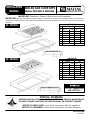
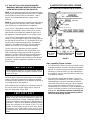
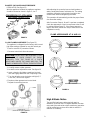
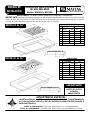
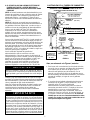
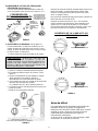
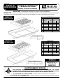
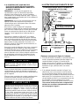
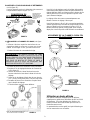
IMPORTANT: Dimensions Shown in Both Inches and Centimeters.
IMPORTANT:
Be sure the appliance being installed is equipped for the gas to be supplied. Refer to serial plate on
underside of burner box for this information. Do not attempt to convert this appliance for use with a gas other than the type
specified.
8101P582-60
(04-04-00)
CUTOUT DIMENSIONS
ARE CRITICAL
30² MODEL
INSTALLATION
MANUAL
SEALED GAS COOKTOPS
Models: MGC5430 & MGC5536
SPECIAL WARNING:
IMPROPER INSTALLATION, ADJUSTMENT, ALTERATION, SERVICE, MAINTENANCE
OR USE OF RANGE CAN RESULT IN SERIOUS INJURY OR PROPERTY DAMAGE.
NOTICE TO INSTALLER: Leave these instructions with the appliance.
NOTICE TO CONSUMER: Retain these instructions for future reference.
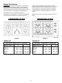
DIMENSIONS
inches cm
A281/2 +
1/16 72.4 + 0.2
B 19 15/16 +
1/16 50.6 + 0.2
C21/8 +
1/16 5.4 + 0.2
D51/4 +
1/16 13.3 + 0.2
E291/2 +
1/16 74.9 + 0.2
F211/2 +
1/16 54.6 + 0.2
G 3 13/16 +
1/16 9.7 + 0.2
H121/4 +
1/16 31.1 + 0.2
36² MODEL
DIMENSIONS
inches cm
A341/2 +
1/16 87.6 + 0.2
B 19 15/16 +
1/16 50.6 + 0.2
C21/8 +
1/16 5.4 + 0.2
D51/4 +
1/16 13.3 + 0.2
E36 +
1/16 91.4 + 0.2
F21 +
1/16 53.3 + 0.2
G 3 13/16 +
1/16 9.7 + 0.2
H151/4 +
1/16 38.7 + 0.2

2
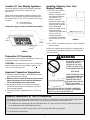
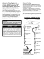
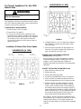
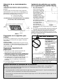
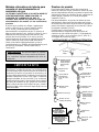
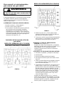
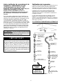
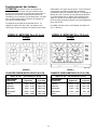
Installing Cabinetry Over Your
Maytag Cooktop
A=30² (76.2 cm) minimum
vertical clearance
between cooking surface
and construction above
the appliance. This
clearance may be
reduced to not less than
24 inches (60.96 cm) by
protecting the underside
of the combustible
material or metal cabinet
above the cooking
surface with not less than
1/4 inch (.635 cm)
insulating millboard
covered with sheet metal
not less than 0.0122 inch
thick.
B=13² (33.02 cm) maximum depth of cabinets installed
above cooktop.
Avoid use of cabinets above cooktop for storage space to
eliminate associated potential hazards such as reaching
over open flames.
Location Of Your Maytag Appliance
Locate this appliance away from combustible materials
such as window curtains and combustible wall
decorations.
Minimum horizontal clearance between the edge of the
appliance and combustible construction extending from
the cooking surface to 18² (45.72 cm) above the cooking
surface is:
1.0² (2.54 cm) at rear
6² (15.24 cm) at sides
(Dimensions apply to both 30²
²²
² and 36²
²²
² wide models).
FIGURE 1
1.0²
2.54 cm
18²
45.72 cm
6²
15.24 cm
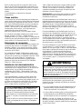
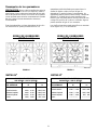
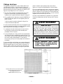
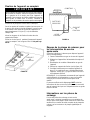
Preparation Of Countertop
The countertop cutout must be prepared according to the
illustration on page 1 of these instructions.
CAUTION: Cutout dimensions are critical. Dimensions
must be measured and cut accurately to within +
1/16²
(.159 cm) to ensure proper fit.
Important Preparation Suggestions
1. Chamfer all exposed edges of decorative laminate to
prevent damage from chipping.
2. Radius corners of cutout and file to insure smooth
edges and prevent corner cracking. Recommend
1/4²
²²
² or 3/8²
²²
² diameter drill in each corner.
3. Rough edges, inside corners which have not been
rounded and forced fits can contribute to cracking of
the countertop laminate.
4. Countertop must be supported within 3² (7.62 cm) of
cutout.
FIGURE 2
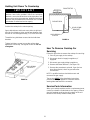
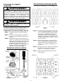
Required Adjustments At Time Of Installation
The installation of this appliance must conform with local codes, or in the absence of local codes, with the latest edition
of the National Fuel Gas Code ANSI Z223.1 USA or current CAN/CGA-B149 INSTALLATION CODE.
V This appliance was manufactured for use with Natural Gas. If LP gas is the fuel of choice, follow the conversion to
LP procedure found in the installation instructions.
V Test all external connections for gas leaks. Never test for gas leaks with an open flame.
V Test all electrical connections.
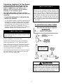
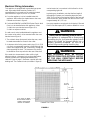
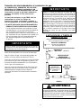
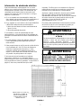
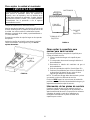
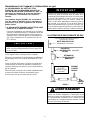
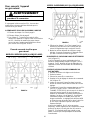
THIS PRODUCT SHOULD NOT
BE INSTALLED BELOW A
VENTILATION TYPE HOOD
SYSTEM THAT DIRECTS AIR
IN A DOWNWARD DIRECTION.
(SEE FIGURE)
THESE SYSTEMS MAY CAUSE
IGNITI ON AND COMBUSTION
PROBLEMS WITH THE GAS
BURNERS RESULTING IN
PERSONAL INJURY AND MAY
AFFECT THE COOKING
PERFORMANCE OF THE UNIT.
NOTE: THE FIGURE MAY NOT ACCURATELY REPRESENT
YOUR RANGE OR COOKTOP; HOW EVER, THIS WARNING
APPLIES TO ALL GAS COOKING PRODUCTS.
WARNING

3
Check the cooktop serial plate to see if the cooktop is
approved for installation in mobile homes and/or
recreational park trailers. Serial plate is located on the
bottom of the unit.
If approved, the following items are applicable:
Mobile Homes
The installation of a range designed for mobile home
installation must conform with the Manufactured Home
Construction and Safety Standard, Title 24 CFR, Part
3280 [formerly the Federal Standard for Mobile Home
Construction and Safety, Title 24 HUD, (Part 280)] or,
when such standard is not applicable, the Standard for
Manufactured Home Installations, ANSI A225.1/NFPA
501A, or with local codes.
In Canada the range must be installed in accordance with
the current CSA Standard C22.1 - Canadian Electrical
Code Part 1 and Section Z240.4.1 - Installation
Requirements for Gas Burning Appliances in Mobile
Homes (CSA Standard CAN/CSA - Z240MH).
Recreational Park Trailers
The installation of a range designed for recreational park
trailers must conform with state or other codes or, in the
absence of such codes, with the Standard for
Recreational Park Trailers, ANSI A119.5-latest edition.
In Canada the range must be installed in accordance with
CAN/CSA - Z240.6.2 - Electrical Requirements for R.V.’s
(CSA Standard CAN/CSA - Z240 RV Series) and Section
Z240.4.2 - Installation Requirements for Propane
Appliances and Equipment in R.V.’s (CSA Standard
CAN/CSA - Z240 RV Series).
Installation Of Appliance
The installation of this appliance must conform with local
codes or, in the absence of local codes, with the National
Fuel Gas Code, ANSI Z223.1-Latest Edition, or, in
Canada, CAN/CGA-B149 Installation Code, Latest
Edition.
This appliance, when installed, must be electrically
grounded in accordance with local codes or, in the
absence of local codes, with the National Electrical Code
ANSI/NFPA No. 70-Latest Edition, or, in Canada, current
CSA Standard C22.1 Canadian Electrical Code, Part 1.
In T h e Commonwealth Of Massachusetts
This product must be installed by a licensed plumber or
gas fitter when installed within the Commonwealth of
Massachusetts.
A “T” handle type manual gas valve must be installed in
the gas supply line to this appliance.
A flexible gas connector, when used, must not exceed a
length of three (3) feet / 36 inches.
All supply piping, except as noted, should use common
National Pipe Thread (N.P.T.). For all pipe connections
use an approved pipe joint compound resistant to the
action of LP gas.
CAUTION: Warranty is void on Maytag equipment
installed other than as recommended by manufacturer.
This appliance is designed for use with the appliance gas
pressure regulator supplied with this appliance. It must be
installed in the gas line ahead of the gas manifold
entrance. It is preset for use with natural gas and must be
converted, as described on pages 8 and 9, for use with
LP gas. (See figures 7 - 12).
This appliance is designed to operate at a pressure of 5
inches of water column (36² models), 4 inches of water
column (30² models) on natural gas or, if converted for
use with LP gas (propane or butane), 10 inches water
column. Make sure this appliance is supplied with and
adjusted for the type of gas for which it is designed.
This appliance was adjusted at the factory for use with
natural gas. If, at any time, this appliance is to be used
with a different type of gas, all of the conversion
adjustments described on pages 8 and 9 must be made
by a qualified service technician before attempting to
operate the cooktop on that gas. Natural gas should be
supplied to the appliance pressure regulator at a line
pressure between 6 and 14 inches of water column or, if
converted for LP gas, between 11 and 14 inches.
If the line pressure supplying the appliance pressure
regulator exceeds 14² water column (any gas), an
external regulator must be installed in the gas line ahead
of the appliance regulator to reduce the pressure to no
more than 14² water column. Failure to do this can result
in malfunction and damage to the appliance.
WARNING
Insure this appliance is adjusted for the type of gas
supplied to it and that the gas supply pressure to the
appliance regulator is within the proper pressure range.
S If no other appliance is to be installed in the cabinetry
below this unit, proceed as instructed under paragraph
1, page 4.
S If this unit is to be installed over a Maytag Model
MEW6500 or MEW5500 Series Electric Wall Oven
proceed as instructed under paragraph 2, page 5.
NOTE: In Canada, gas utilization codes prohibit use of
street elbows. Use standard pipe elbows and make
modifications to these instructions as necessary.

4
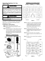
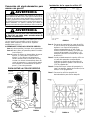
Connecting Appliance To Gas Supply
A QUALIFIED SERVICE TECHNICIAN OR GAS
APPLIANCE INSTALLER MUST MAKE THE GAS
SUPPLY CONNECTION. Leak testing of the
appliance shall be conducted by the installer
according to the instructions given.
Gas supply piping MUST conform to all local,
municipal and state building codes and local utility
regulations.
1. IF NO OTHER APPLIANCE IS TO BE INSTALLED
BELOW THIS COOKTOP
Join the appliance pressure regulator supplied with this
appliance to the entrance threads of the Gas Manifold.
The appliance regulator is marked with a directional
arrow indicating correct direction of gas flow. Ensure
the appliance regulator is installed with the arrow
pointing toward the gas manifold entrance. Tighten the
appliance regulator to 20 to 30 ft-lbs of torque.
IMPORTANT
Never tighten to more than 35 ft-lbs of torque. Always
use an approved pipe joint compound resistant to the
action of LP gas.
Install the appliance in its counter cutout.
Make the gas connection to the inlet of the appliance
pressure regulator with 1/2² NPT male pipe threads.
Install a manual shut-off valve in an accessible location in
the gas line ahead of the appliance pressure regulator
and external to this appliance for the purpose of turning
on or shutting off gas to the appliance.
Make additional pipe connections as necessary ahead of
the shut-off valve to the gas supply source. Assure all
pipe joint connections are gas tight.
IMPORTANT
Applyanon-corrosiveleakdetectionfluidtoalljointsand
fittings in the gas connection between the supply line
shut-off valve and the cooktop. Include gas fittings and
joints in the cooktop if connections were disturbed
during installation. Check for leaks! Bubbles appearing
around fittings and connections will indicate a leak. If a
leak appears, turn off supply line gas shut-off valve,
tighten connections, turn on the supply line gas shut off
valve, and retest for leaks. Never test for gas leaks with
an open flame.
FIGURE 3
ILLUSTRATIVE GAS SUPPLY PIPING
(3/8² N.P.T.)
ALL SUPPLY SIDE
PIPE JOINTS
1/2² N.P.T.
Gas leaks may occur in your system and result in a
dangerous situation. Gas leaks may not be detected by
smell alone. Gas suppliers recommend you purchase and
install an UL approved gas detector. Install and use in
accordance with the manufacturer’s instructions.
WARNING

5
2. IF THIS UNIT WILL HAVE A MAYTAG MODEL
MEW6500 or MEW5500 SERIES ELECTRIC WALL
OVEN INSTALLED BELOW THIS COOKTOP.
NOTE 1: This appliance and its gas and electrical supply
sources must be installed before the wall oven is installed.
See illustration (Electrical Wiring Information - page 7;
figure 6) for recommended electrical supply source
locations.
NOTE 2: It may be necessary to extend gas supply piping
for this appliance into adjacent under-counter cabinetry
when a wall oven is installed below this appliance.
Joina3/8² NPT pipe elbow (locally available) to the male
threads at the manifold entrance. When joined, ensure
open threads of the elbow face toward the right side of
the appliance. Install the appliance in its counter cutout.
Joina3/8² NPT pipe nipple to the elbow using a pipe
section of sufficient length to extend, horizontally, beyond
the right side of the wall oven. (To accomplish this it may
be necessary to extend the pipe section into adjacent
cabinetry.) Join additional 3/8² NPT elbow(s) and pipe
nipples, as necessary, to accomplish the following:
Join the outlet of the appliance pressure regulator
supplied with this appliance to the male threads of the
newly installed gas supply piping. Install the appliance
regulator in a location which will be accessible beside or
below the wall oven. Insure the appliance regulator is
installed with its directional arrow pointing in the direction
of gas flow. Tighten the appliance regulator to 20 to 30
ft-lbs of torque.
IMPORTANT
Never tighten to more than 35 ft-lbs of torque. Always
use an approved pipe joint compound resistant to the
action of LP gas.
Locate and join a manual shut-off valve in an accessible
location in the gas line ahead of the appliance regulator
and external to the appliance for the purpose of turning on
or shutting off gas to the appliance.
Make additional pipe connections as necessary ahead of
the shut-off valve to the gas supply source. Assure all
pipe joint connections are gas tight.
IMPORTANT
Apply a non-corrosive leak detectionfluid to all joints and
fittings in the gas connection between the supply line
shut-off valve and the cooktop. Include gas fittings and
joints in the cooktop if connections were disturbed during
installation. Check for leaks! Bubbles appearing around
fittings and connections will indicate a leak. If a leak
appears, turn off supply line gas shut-off valve, tighten
connections, turn on the supply line gas shut off valve,
andretestforleaks. Nevertest forgas leaks with anopen
flame.
FIGURE 4
ILLUSTRATIVE GAS SUPPLY PIPING
(WALL OVEN I NST AL LED BELOW 30²
²²
² COOKTOP)
(3/8² N.P.T.)
ALL SUPPLY SIDE
PIPE JOINTS
1/2² N.P.T.
ALL UNIT SIDE
PIPE JOINTS
3/8² N.P.T.
Note, regarding Figure 4, above:
S For convenience in service a union (not shown: locally
available) should be included in the piping illustrated in
figure 4, in a location most practical for the installation.
Generally, a practical location is in the cabinet below
this appliance, near the manifold entrance, rather than
in an adjoining cabinet.
S If the alternative piping method shown in figure 5 is
selected for the installation, no union is required. (The
flexible appliance connector illustrated provides the
union joints necessary for servicing.) When a dividing
wall is present and a flexible connector is used it is
recommended for convenience, in both installation and
service, the flexible connector, itself, pass through the
dividing wall. Any flexible connector used with this
appliance must satisfy all requirements stated in
the text accompanying figure 5.

6
Alternative Piping Methods To
Connect Appliance To Gas Supply
A TRAINED SERVICE TECHNICIAN OR GAS
APPLIANCE INSTALLER MUST MAKE THE GAS
SUPPLY CONNECTION. Leak testing of the
appliance shall be conducted by the installer
according to the instructions given.
Unless prohibited by local codes or ordinances, a new
A.G.A. - Certified, flexible metal appliance connector may
be used to connect this appliance to its gas supply. The
connector must be no more than 5 feet in length. Per
figure 5, use appropriate flare union adapter at each end
of the flexible connector. If a flexible connector is used
assure that both the appliance pressure regulator and
manual shut-off valve are joined solidly to other
permanent hard piping (either gas supply or the appliance
manifold) so as to be physically stationary. See
illustrations below.
CAUTION: Do not attempt to a ttach the flexible
connector directly to an external pipe thread.
Connection requires flare union adapters.
IMPORTANT
Apply a non-corrosive leak detectionfluid to all joints and
fittings in the gas connection between the supply line
shut-off valve and the range. Include gas fittings and
joints in the range if connections were disturbed during
installation. Check for leaks! Bubbles appearing around
fittings and connections will indicate a leak. If a leak
appears, turn off supply line gas shut-off valve, tighten
connections, turn on the supply line gas shut off valve,
andretestforleaks. Nevertest forgas leaks with anopen
flame.
Pressure Testing
The appliance must be isolated from the gas supply
piping system by closing its individual manual shut-off
valve during any pressure testing of the gas supply piping
system at test pressures equal to or less than 1/2 pounds
per square inch (3.5 kPa).
This appliance, as well as its individual shut-off valve,
must be disconnected from the gas supply piping system
during any pressure testing of the system at test
pressures in excess of 1/2 pounds per square inch (3.5
kPa).
When checking appliance regulator function, make certain
pressure of natural gas supply is between 6 and 14
inches of water column or, if converted for LP gas,
between 11 and 14 inches of water column.
FIGURE 5
ILLUSTRATIVE ALTERNATIVE PIPING
3/8² N.P.T.
Elbow
3/8² N.P.T. Flexible
Appliance Connector
(5 ft. max.)
1/2² N.P.T. Flexible
Appliance Connector
(5 ft. max.)
Appliance Pressure
Regulator, Supplied
(Observe directionality
of Gas Flow)
Flare Union Adaptor
Flare Union Adaptor
Gas Shut-Off Valve
1/2² N.P.T. Pipe
(Stationary Supply Pipe)
Flare Union
Adaptor
Flare Union Adaptor
Appliance Pressure
Regulator, Supplied
(Observe
directionality of Gas
Flow)
1/2² N.P.T. Pipe
Nipple
Gas Shut-Off Valve
1/2² N.P.T. Pipe
(Stationary Supply
Pipe)
Manifold
Entrance

7
Electrical Wiring Information
This appliance is equipped with a grounded type power
cord. A grounded outlet must be provided. It is
recommended, for convenience, the outlet be located
(with reference to figure 6) as in A or B, below:
A. If no other appliance is to be installed below this
appliance: within either the shaded area or the cross
hatched area shown in figure 6.
B. If a Model MEW6500 or MEW5500 Series Electric Wall
Oven is to be installed below this appliance, either:
1. within the cross hatched area of figure 6, or,
2. within an adjacent cabinet.
If a wall oven is to be installed below this appliance and
the counter units outlet is to be mounted within the cross
hatched area of figure 6:
1. The cabinet’s lower front panel, below the oven, must
be made removable for access to the outlet.
2. A clearance hole for the power cord’s plug (1-1/4² (3.18
cm) dia is recommended) must be provided through the
oven’s floor support shelf and, if necessary, through the
slats supporting the shelf. The clearance hole should
be located as near as practical to the rear of the shelf.
If the outlet is to be mounted in either a left or right
adjacent cabinet, a clearance hole, as described above,
must be provided in the dividing wall between the
cabinets. Figure 4; page 5, illustrates a typical (left side)
dividing wall. The clearance hole (not shown in figure 4)
can be located as is convenient in this left wall or in the
corresponding right wall.
In planning any installation, note that the free length of
this appliance’s power cord, extending beyond a point
3-3/4² (9.53 cm) left of the nominal center of the rear wall
of the burner box, when viewed from the front of the unit,
is approximately 46² (117 cm).
User may experience occasional circuit tripping if Ground
Fault Circuit Interrupter (GFCI) outlet or breaker is in use.
Electrical Grounding Instructions
This appliance is equipped with a (three-prong)
grounding plug for your protection against shock
hazard and should be plugged directly into a
properly grounded receptacle. Do not cut or
remo ve the grounding prong from this plug.
WARNING
THIS APPLIANCE MUST BE DISCON-
NECTED FROM ITS ELECTRICAL SUPPLY
AT THE WALL RECEPTACLE BEFORE
SERVICING THE APPLIANCE.
WARNING
FIGURE 6
31/2² (8.89 cm) WIDE
SLATS WHEN A WALL
OVEN IS INSTALLED
BELOW 30² MODEL
4² MAX.
10.16 cm
37 3/16²
94.46 cm
29 3/8²
74.61 cm
3 13/16²
9.7 cm
CABINET BOTTOM

8
Converting Appliance For Use
With LP Gas
Propane conversion is to be performed by a MAYTAG
AUTHORIZED SERVICER (or other qualified agency) in
accordance with the manufacturer’s instructions and all
codes and requirements of the authority having
jurisdiction. Failure to follow instructions could result in
serious injury or property damage. The qualified agency
performing this work assumes responsibility for this
conversion.
WARNING
Electrical p o wer and gas must b e turned off
prior to conversion.
WARNING
This appliance was adjusted at the factory for use with
natural gas. To convert it for use with LP gas (propane or
butane), each of the following modifications must be
performed: (A, B, and C)
A. REPLACE ALL ORIFICE SPUDS
Step 1: Remove the grates and burner caps.
Step 2: Remove burner base by removing 2 screws.
(See figure 7).
Step 3: Firmly press 9/32² (or 7mm) nut driver over the
orifice spud (figures 7 and 8) and loosen spud
by turning counter- clockwise. Carefully lift nut
driver out of burner throat. Orifice spud should
be captured in the nut driver. Repeat steps 2 &
3 for each burner.
FIGURE 7
REMOVAL OF ORIFICE SPUD
FIGURE 8
Orifice
Spud
FIGURE 9
Installation Of LP Orifice Spud
Step 4: Locate the LP orifice spud packet included in
the literature packet. The spuds have small
numbers stamped on the side. This number
codes the orifice diameter and its correct
burner location. Figure 9 and 10 show the
correct LP orifice spud location.
Step 5: Carefully install the orifice spud in the
appropriate burner throat by turning clockwise
to tighten. Tighten to a torque of 15 to 20
inch-lbs.
Step 6: Replace burner base, caps, and grates.
Tighten screws (do not cross thread) to 25-30
in lbs.
Step 7: Save the orifices removed from the appliance
for future use.
FIGURE 10
0.91
0.91
0.64
0.97

9
B. INVERT CAP IN APPLIANCE PRESSURE
REGULATOR (See figure 11)
With the appliance installed, the appliance regulator
should be located as shown in figure 3, 4 or 5.
FIGURE 11
CONVERSION OF APPLIANCE
PRESSURE
REGULATOR
C. LOW FLAME ADJUSTMENT (See figure 12)
This appliance is shipped from the factory with low and
high flame settings adjusted for use with natural gas.
To set for use with LP proceed as follows:
1. Remove control knob from valve stem.
CAUTION: NEVER USE A METAL BLADE TO PRY
KNOB OFF. IF KNOB CANNOT BE EASILY
REMOVED, TUCK THE FOLDS OF A CLOTH
DISHTOWEL UNDER THE KNOB AND PULL THE
TOW EL UPWARDWITHST EADY, EVENPRESSURE.
2. Carefully remove rubber grommet.
3. Locate the valve adjustment screw. See figure 12.
4. Insert a slender, thin-blade screwdriver into knob
hole and engage blade with slot in adjusting screw.
5. Turn the adjusting screw clockwise until tight (5-7
in-lbs max.). Do not over tighten.
6. Replace rubber grommet and control knob.
7. Repeat for remaining burners.
FIGURE 12
KNOB
ADJUSTMENT
SCREW
KNOB HOLE
(KNOB AND GROMMET REMOVED)
After adjusting the screw the burner should produce a
stable, steady blue flame of minimum size. The setting
should be checked by turning knob from high to low
several times without extinguishing the flame.
This operation will automatically provide the proper flame
size at medium setting.
After Conversion Steps A, B and C have been completed,
check the appearance of each burner flame at the Hi and
Lo settings against figure 13. If the flames appear too
large or too small, review each step to make sure it was
completed correctly.
FIGURE 13
FLAME APPEARANCE AT HI AND LO
High Altitude Notice
The specified gas burner ratings typically apply to
elevations up to 2000 feet. For higher altitudes, the rates
may need to be reduced to achieve satisfactory operation.
A local certified gas servicer will be able to advise if a
reduction is necessary.

10
To Convert Appliance For Use With
Natural Gas
Electrical p o wer and gas must b e turned off
prior to conversion.
WARNING
If this appliance has been converted for use with LP gas,
each of the following modifications must be performed to
convert the unit back to natural gas.
A. REPLACE ALL ORIFICE SPUDS.
1. Perform Steps 1 and 2 on page 8.
2. Perform Step 3 on page 8.
3. For Step 4: Locate the brass natural gas orifice
spuds that were originally installed in this appliance
before its conversion for use with LP gas. Observe
the number on each of the spuds and note the
correct burner location for each spud as shown in
figures 14 and 15.
FIGURE 14
Installation Of Natural Gas Orifice Spuds
5 BURNER MODEL (36² WIDE)
FIGURE 15
4 BURNER MODEL (30² WIDE)
1.10
1.55
1.85
1.55
4. Complete Steps 5, 6 and 7 on page 8 to complete
the installation of natural gas main spuds in their
correct locations.
5. Save the orifices removed from the appliance for
future use. They will be needed if this appliance is
again converted for use with LP gas.
B. INVERT CAP IN APPLIANCE PRESSURE
REGULATOR. (See figure 11).
With the appliance installed the appliance regulator
should be located as shown in either figure 3, 4 or 5
(pages 4, 5 & 6). Identify the type of appliance
regulator and follow the instructions in the appropriate
illustration.
C. RESET THE VALVES FOR NATURAL GAS
1. Light one burner, and set on low.
2. Remove the knob.
3. Remove the rubber grommets.
4. Locate the valve adjustment screw. See figure 12.
5. Insert a slender, thin-blade screwdriver into knob
hole and engage blade with slot in adjusting screw.
6. Starting from the LP position (see #5 on page 9,
under C. LOW FLAME ADJUSTMENT), turn the
screw counter clockwise until the flame stabilizes
and matches the pictured “low” setting on figure 13.
Proper adjustment will produce a stable, steady blue
flame of minimum size. The final adjustment should
be checked by turning the knob from high to low
several times without extinguishing the flame.
After Steps A, B and C have been completed, check
the appearance of each burner’s flame at the Hi and Lo
settings against figure 13. If the flames appear too
large or too small, make sure all steps were completed
correctly.

11
Burner Performance
CAUTION: Never cover control knobs or surrounding
control surface with utensils, towels, or other objects.
Never obstruct free air passage past the control knobs.
The knob openings have been sized to properly control air
entry to the interior of the appliance during operation.
This appliance has no air shutters. Primary air
adjustments are unnecessary. The burners are designed
to provide optimum aeration for all gases without air
shutters. When operating properly, burners should
produce clearly defined, even blue flames. If the flames
have yellow tips or are hazy and otherwise appear to
have insufficient air, obtain the services of a qualified
service technician. Some yellow tipping on LP gas is
normal.
Specified input rates are as shown in figures 16 and 17
below.
BURNER LOCATION Hi Lo
Right Front 12,500 / 10,500 1300 / 1300
Right Rear 9,200 / 9,100 1300 / 1300
Left Front 9,200 / 9,100 1300 / 1300
Left Rear 5000 / 4000 650 / 650
C e n t e r -- -- -- -- -- -- -- -- -- -- -- -- -- -- -- -- -- -- -- -- -- --
INPUT RATES - NATURAL GAS / LP GAS (BTU/HR)
FIGURE 16
5 BURNER MODEL (36²
²²
² Wide)
MAYTAG 30²
²²
²
FIGURE 17
MAYTAG 36²
²²
²
BURNER LOCATION Hi Lo
Right Front 12,500 / 10,500 1300 / 1300
Right Rear 9,200 / 9,100 1300 / 1300
Left Front 9,200 / 9,100 1300 / 1300
Left Rear 10,500 / 9,100 1300 / 1300
Center 5,000 / 4,000 650 / 650
INPUT RATES - NATURAL GAS / LP GAS (BTU/HR)
4 BURNER MODEL (30²
²²
² Wide)

12
Holding Unit Down To Countertop
IMPORTANT
To hold the cooktop to the counter top, two hold down
brackets have been provided. Utilize the hold-down
brackets, one on the left and one on the right side of unit
tosecuretheunittothecountertop.Additionalhold-down
brackets may be added to the front and/or rear. Contact
your dealer or authorized service agency.
Position the cooktop in the cutout opening.
Open cabinet doors and locate screw holes at right and
left side of unit bottom. Holes are half way between front
and rear of unit and approximately 1 1/4² from each side.
Thread the long hold-down screws into the hold-down
brackets.
Tighten hold-down screws to snug the unit top down
against the counter top. See figures 18 and 19. Do not
overtighten.
FIGURE 18
HOLD-DOWN
BRACKET
FIGURE 19
COUNTERTOP
BURNER BOX
HOLD-DOWN
SCREW
HOLD-DOWN
BRACKET
How To Remove Cooktop For
Servicing
Follow this procedure to remove the cooktop for servicing:
1. Shut off gas supply to the cooktop.
2. Disconnect electrical supply to appliance, if
equipped.
3. Disconnect gas supply tubing to appliance.
4. Remove hold down brackets. (See figure 19).
5. Reverse the procedure to reinstall. If gas line has
been disconnected, check for gas leaks after
reconnection.
NOTE: A qualified servicer should disconnect and
reconnect the gas supply.
The servicer MUST
follow installation instructions
provided with the gas appliance connector and the
warning label attached to the connector.
Service -Parts Information
When your cooktop requires service or replacement parts,
contact your dealer or authorized service agency. Please
give the complete model and serial numbers of the unit
located on the cooktop model number plate.

MODELO de 36”
403 WEST FOURTH STREET, NORTH · NEWTON, IA 50208
IMPORTANTE: Las dimensiones aparecen en pulgadas y centímetros.
IMPORTANTE:
Asegúresedequeelelectrodomésticoqueseinstalaráestéequipadoconelgasquese surtirá.Consulte
la placa de datos que se encuentra en la parte inferior de la caja del quemador para obtener esa información. No trate de
convertir este electrodoméstico para usar otro tipo de gas que el que se especifica.
LAS DIMENSIONES DE
CORTE DEL HUECO
SON MUY
IMPORTANTES
MANUAL DE
INSTALACIÓN
SUPERFICIES PARA COCINAR
DE GAS SELLADAS
Modelos: MGC5430 y MGC5536
ADVERTENCIA ESPECIAL:
LA INSTALACIÓN, EL AJUSTE, LA ALTERACIÓN, EL SERVICIO, EL MANTENIMIENTO
O EL USO INCORRECTOS DE LA ESTUFA PUEDEN CAUSAR LESIONES GRAVES O
DAÑOS MATERIALES.
AVISO AL INSTALADOR: Deje estas instrucciones con el electrodoméstico.
AVISO AL CONSUMIDOR: Conserve estas instrucciones para consultarlas en el futuro.
DIMENSIONES
pulgadas cm
A281/2 +
1/16 72,4 + 0,2
B 19 15/16 +
1/16 50,6 + 0,2
C21/8 +
1/16 5,4 + 0,2
D51/4 +
1/16 13,3 + 0,2
E291/2 +
1/16 74,9 + 0,2
F211/2 +
1/16 54,6 + 0,2
G 3 13/16 +
1/16 9,7 + 0,2
H121/4 +
1/16 31,1 + 0,2
DIMENSIONES
pulgadas cm
A341/2 +
1/16 87,6 + 0,2
B 19 15/16 +
1/16 50,6 + 0,2
C21/8 +
1/16 5,4 + 0,2
D51/4 +
1/16 13,3 + 0,2
E36 +
1/16 91,4 + 0,2
F21 +
1/16 53,3 + 0,2
G 3 13/16 +
1/16 9,7 + 0,2
H151/4 +
1/16 38,7 + 0,2
IMPORTANTE
MODELO de 30”

2
Instalación de gabinetes por encima
de la superficie para cocinar Maytag
A=30² (76,2 cm) de espacio
libre vertical mínimo
entre la superficie para
cocinar y la construcción
que está por encima del
electrodoméstico. Este
espacio puede reducirse
a no menos de 24
pulgadas (60,96 cm) si
se protege el lado inferior
del material combustible
o del gabinete de metal
que está por encima de
la superficie para cocinar
con cuando menos
1/4 pulgadas (0,635 cm)
de un aislante de
partículas de madera con
una hoja metálica de cuando menos 0,0122 pulgadas
de espesor.
B=13² (33,02cm)deprofundidadmáximadelosgabinetes
instalados por encima de la superficie para cocinar.
Evite usar los gabinetes que están por encima de la
superficie para cocinar para almacenar artículos a fin de
eliminar los riesgos potenciales al atravesarse por encima
de la llama para alcanzar algo.
Ubicación de su electrodoméstico
Maytag
Coloque este electrodoméstico alejado de materiales
combustibles como cortinas de ventanas y decoraciones
de pared.
El espacio libre horizontal mínimo entre el borde del
electrodoméstico y la construcción combustible que se
extiende de la superficie para cocinar a 18² (45,72 cm)
por encima de la superficie para cocinar es:
1,0² (2,54 cm) por detrás
6² (15,24 cm) a los lados
(Las dimensiones corresponden tanto a los modelos
de 30²
²²
² como a los de 36²
²²
² de ancho.)
FIGURA 1
1,0²
2,54 cm
18²
45,72 cm
6²
15,24 cm
Preparación de la superficie para
cocinar
El recorte de la superficie para cocinar debe prepararse
de acuerdo con la ilustración de la página 1 de estas
instrucciones.
PRECAUCIÓN: Las dimensiones del corte son muy
importantes. Las dimensiones deben medirse y cortarse
con precisión a +
1/16² (0,159 cm) para garantizar un
ajuste correcto.
Sugerencias importantes de
preparación
1. Alise todos los bordes expuestos del laminado
decorativo para evitar que se quiebren.
2. Redondee las esquinas del recorte y límelas para
evitar que se estrellen. Se recomienda una broca
de 1/4²
²²
² o3/8²
²²
² de diámetro en cada esquina.
3. Los bordes burdos, las esquinas interiores que no se
han redondeado y los ajustes forzados pueden
contribuir a que se resquebraje el laminado del
mostrador.
4. El mostrador debe estar apoyado a menos de 3²
(7,62 cm) del recorte.
FIGURA 2
Ajustes necesarios al momento de la instalación
La instalación de este electrodoméstico debe estar en conformidad con los códigos locales, o si no existieran los
mismos, con la última edición del Código Nacional de Gas Combustible ANSI Z223.1 USA o el CÓDIGO DE
INSTALACIÓN actual CAN/CGA-B149.
V Este electrodoméstico se fabricó para usarse con gas natural. Si se elige usar gas LP, siga los procedimientos de
conversión LP que se encuentran en las instrucciones de instalación.
V Revise todas las conexiones externas para detectar fugas de gas. Nunca realice pruebas de fugas de gas con una
llama encendida.
V Revise todas las conexiones eléctricas.
ESTE PRODUCTO NO DEBE
INSTALARSE DEBAJO DE
UNA CAMPANA DE
VENTILACIÓN QUE DIRIJA EL
AIRE EN UNA DIRECCIÓN
HACIA ABAJO.
(VEA LA FIGURA)
ESTOS SISTEMAS DE
VENTILACIÓN PUEDEN
CAUSAR PROBLEMAS D E
IGNICIÓN Y DE
COMBUSTIÓN CON LOS
QUEMADORES A GAS
RESULTANDO EN LESIONES
PERSONALES Y PUEDEN
AFECTAR LA MANERA DE
COCINAR DE LA UNI DAD.
NOTA: ES POSIBLE QUE LA FIGURA NO SEA UNA REPRESENTA-
CIÓN EXACTA DE SU ESTUFA O DE SU SUPERFICIE PARA C OCI-
NAR; SIN EMBARGO, ESTA ADVERTENCIA SE APLICA A TODOS
LOS ELECTRODOMÉSTICOS DE COCINA A GAS.
ADVER TENCIA

3
Revise la placa de datos de la superficie para cocinar
para ver si esta última está aprobada para instalarse en
casas móviles y/o en remolques de recreación. La placa
de datos se encuentra localizada en la parte inferior de la
unidad.
Si está aprobada, se aplicarán las siguientes
estipulaciones:
Casas móviles
La instalación de una estufa diseñada para instalarse en
casas móviles debe estar en conformidad con las Normas
de Construcción y Seguridad de casas móviles, Título 24
CFR, Parte 3280 [anteriormente conocida como Normas
Federales para la Construcción y Seguridad de Casas
Móviles, Título 24 HUD, (Parte 280)] o bien, cuando no
corresponden dichas normas, con las Normas para
instalaciones de casas prefabricadas,
ANSI A225.1/NFPA 501A, o con los códigos locales.
En Canadá la estufa debe instalarse de acuerdo con las
Normas actuales CSA C22.1 — Código eléctrico
canadiense Parte 1 y la Sección Z240.4.1 — Requisitos de
instalación para electrodomésticos de gas combustible en
casas móviles (CSA Standard CAN/CSA - Z240MH).
Remolques de recreación
La instalación de una estufa diseñada para remolques de
recreación debe estar en conformidad con los códigos
estatales y demás o, en la ausencia de dichos códigos,
con la última edición de las Normas para remolques de
recreación, ANSI A119.5.
En Canadá la estufa debe instalarse de acuerdo con la
norma CAN/CSA - Z240.6.2 — Requisitos eléctricos para
vehículos de recreación (CSA Standard CAN/CSA - Z240
RV Series) y la Sección Z240.4.2 — Requisitos de
instalación para electrodomésticos y equipo de gas
propano en vehículos de recreación (CSA Standard
CAN/CSA - Z240 RV Series).
Instalación del electrodoméstico
La instalación de este electrodoméstico debe estar en
conformidad con los códigos locales o, en la ausencia de
códigos locales, con el Código nacional de gas
combustible, ANSI Z223.1 - última edición, o bien, en
Canadá, Código de instalación CAN/CGA-B149, última
edición.
Este electrodoméstico, cuando se instala, debe estar
conectado a tierra eléctricamente de acuerdo con los
códigos locales o, en la ausencia de códigos locales, con
el Código nacional eléctrico ANSI/NFPA No. 70-última
edición, o, en Canadá, con las Normas actuales CSA
C22.1 Código eléctrico canadiense, Parte 1.
En la Commo n wealth de Massachu setts
Este producto debe instalarse por un plomero o un
instalador de gas certificado cuando está instalado
dentro de la Commonwealth de Massachusetts.
Debe instalarse en el electrodoméstico una válvula de
gas tipo ”T” manual en la tubería del suministro de
gas.
Cuando se utiliza un conector flexible de gas, no debe
exceder una longitud de tres (3) pies o 36 pulgadas
(91,4 cm).
Toda la tubería de suministro, excepto cuando se indica,
debe ser de tipo común de rosca NPT (National Pipe
Thread). Use en todas las conexiones de tubería un
compuesto aprobado para uniones de tubería que sea
resistente a la acción del gas LP.
PRECAUCIÓN: La garantía queda anulada en el equipo
Maytag que se instale de manera diferente a la que
recomienda el fabricante.
Este electrodoméstico está diseñado para usarse con el
regulador de presión de gas que se incluye con el mismo.
Debe instalarse en la tubería de gas, antes de la entrada
del múltiple de gas. Está previamente ajustado para
usarse con gas natural y debe convertirse, según se
describe en las páginas 8 y 9, para poder usarse con gas
LP. (Vea las figuras 7 —12).
Este electrodoméstico está diseñado para funcionar a
una presión de 5 pulgadas de columna de agua (en los
modelos de 36”), con 4 pulgadas de columna de agua (en
los modelos de 30”) con gas natural, o bien, si se
convierte para usarse con gas LP (propano o butano),
con 10 pulgadas de columna de agua. Asegúrese de que
este electrodoméstico tenga y esté ajustado para usar el
tipo de gas para el cual se diseñó.
Este electrodoméstico se ajustó de fábrica para usarse
con gas natural. Si, en algún momento, se usará este
aparato con otro tipo de gas, un técnico calificado deberá
hacer todos los ajustes de conversión que se describen
en las páginas 8 y 9 antes de tratar de operar la
superficie para cocinar con ese gas. El gas natural
deberá surtirse al regulador de presión a una presión de
tubería de entre 6 y 14 pulgadas de columna de agua, o
si se convierte a gas LP, a una presión de entre 11 y
14 pulgadas.
Si la presión de tubería suministrada al regulador de
presión excede las 14 pulgadas de columna de agua (en
cualquiergas),deberá instalarseunreguladorexternoen
la tubería de gas antes del regulador de presión para
reducir la presión a no más de 14 pulgadas de columna
deagua.Nohacerlopodría causarel malfuncionamiento
y daños al electrodoméstico.
ADVER TENCIA
Asegúrese de que este electrodoméstico esté ajustado
para el tipo de gas suministrado y que la presión del
suministro de gas al regulador está dentro de la tasa de
presión adecuada.
S Si no se instalará ningún otro electrodoméstico en los
gabinetes debajo de esta unidad, proceda según se
indica bajo el párrafo 1 de la página 4.
S Si esta unidad se instalará sobre un horno eléctrico de
pared Maytag de la serie MEW6500 o MEW5500
proceda según se indica en el párrafo 2 de la página 5.
NOTA: En Canadá, los códigos de utilización de gas
prohiben el uso de codos de hembra y macho. Use codos
de tubería estándar y haga las modificaciones necesarias
a estas instrucciones.

4
Conexión del electrodoméstico al suministro de gas
LA CONEXIÓN DEL SUMINISTRO DE GAS DEBE
REALIZARLA UN TÉCNICO CALIFICADO O UN
INSTALADOR DE ELECTRODOMÉSTICOS DE GAS.
Las pruebas de fugas de gas debe realizarlas el
instalador de acuerdo con las instrucciones
provistas.
La tubería de suministro de gas DEBE estar en
conformidad con todos los códigos de
construcción locales, municipales y estatales, y
con los reglamentos de servicios públicos locales.
1. SI NO SE INSTALARÁ UN ELECTRODOM ÉSTICO
DEBAJO DE ESTA SUPERFICIE PARA COCINAR
Una el regulador de presión que se adjunta con este
electrodoméstico a la rosca de entrada del múltiple de
gas. El regulador está marcado con una flecha
direccional que indica la dirección correcta del flujo de
gas. Asegúrese de que el regulador esté instalado con
la flecha apuntando hacia la entrada del múltiple de
gas. Apriete el regulador a una torsión de 20 a
30 pies-lbs.
IMPORTANTE
Nunca lo apriete a una torsión mayor de 35 pies-lbs.
Siempreuse uncompuesto aprobadopara unionesque
sea resistente a la acción del gas LP.
Instale el electrodoméstico en el recorte del mostrador.
Haga la conexión de gas a la entrada del regulador de
presión con roscas macho de tubería NPT de 1/2².
Instale una válvula de cierre manual en un lugar accesible
en la tubería de gas antes del regulador de presión y en
el exterior de este electrodoméstico con el fin de abrir o
cerrar el gas al electrodoméstico.
Haga las conexiones adicionales de la tubería que sean
necesarias antes de la válvula de cierre a la fuente de
suministro de gas. Asegúrese de que todas las
conexiones de uniones de la tubería estén firmemente
ajustadas.
IMPORTANTE
Aplique un líquido de detección de fugas que sea
anticorrosivo en todas las uniones y los accesorios de
laconexióndegasentrelaválvuladecierredelatubería
de suministro y la superficie para cocinar. Incluya los
accesorios de gas y las uniones de la superficie para
cocinar si se alteraron las conexiones durante la
instalación. Revise si hay fugas. Si aparecen burbujas
alrededor de los accesorios y las conexiones querrá
decir que hay fugas. Si ocurre esto, cierre la válvula de
cierre de la tubería de suministro de gas, apriete las
conexiones, abra la válvula de cierre de la tubería de
gas, y vuelva a comprobar si hay fugas. Nunca haga
pruebas de fugas de gas utilizando una llama
encendida.
FIGURA 3
ILUSTRACIÓN DE LA TUBERÍA DE
SUMINISTRO DE GAS
(3/8² N.P.T.)
TODAS LAS
UNIONES DE
TUBERÍA LATERAL
DE SUMINISTRO
1/2² N.P.T.
(SIN NINGÚN ELECTRODOMÉSTICO DEBAJO
DE LA SUPERFICIE PARA COCINAR)
CAJA DEL QUEMADOR
(PARTE POSTERIOR DEL
ELECTRODOMÉSTICO)
ENTRADA AL
MÚLTIPLE
REGULADOR DE
PRESIÓN DEL
ELECTRODOMÉSTICO
VÁLVULA
MANUAL DE
CIERRE
HACIA LA
ENTRADA
DE GAS
CODO
Puede ocurrir un escape de gas en susistema y provocar
una situación peligrosa. Los escapes de gas no pueden
ser detectados por elolor solamente. Los proveedores de
gasrecomiendan que compre einstale undetector degas
aprobadoporellaboratorioUL.Instleloyúselodeacuerdo
con las instrucciones de fabricante.
ADVER TENCIA

5
2. SI SE INSTALARÁ UN HORNO ELÉCTRICO DE
PARED MAYTAG DE LA SERIE MEW6500 O
MEW5500 DEBAJO DE ESTA SUPERFICIE PARA
COCINAR.
NOTA 1: Deberá instalarse este electrodoméstico y sus
fuentes de suministro de gas y eléctrico antes de instalar
el horno de pared. Vea la ilustración (Información de
alambrado eléctrico — en la página 7, figura 6) para
encontrar las ubicaciones recomendadas del suministro
eléctrico.
NOTA 2: Podría ser necesario tener que extender la
tubería de suministro de gas de este electrodoméstico a
los gabinetes inferiores adyacentes cuando se vaya a
instalar un horno de pared debajo del electrodoméstico.
Una un codo de tubería NTP de 3/8² (disponible
localmente) a las roscas macho de la entrada del
múltiple. Una vez unidas, asegúrese de que las roscas
abiertas del codo estén orientadas hacia el lado derecho
del electrodoméstico. Instale el electrodoméstico en el
hueco del mostrador.
Una un niple de tubería NPT de 3/8² al codo usando una
sección de tubería lo suficientemente larga para que se
extienda, horizontalmente, más lejos del lado derecho del
horno de pared. (Para hacer esto, podría ser necesario
tener que extender la sección de la tubería hasta adentro
del gabinete adyacente.) Una los codos adicionales de
tubería NPT de 3/8² y los niples de la tubería, según sea
necesario para lograr lo siguiente:
Una la salida del regulador de presión del
electrodoméstico que se suministra con este
electrodoméstico a las roscas macho de la tubería de
suministro de gas recién instalada. Instale el regulador de
presión en un lugar que sea accesible a un lado o por
debajo del horno de pared. Asegúrese de que el
regulador de presión esté instalado con la flecha de
dirección apuntando en la dirección del flujo del gas.
Apriete el regulador a una torsión de 20 a 30 pies-lbs.
IMPORTANTE
Nunca lo apriete a más de 35 pies-lbs de torsión.
Siempre use un compuesto para juntas de tubería que
esté aprobado y que sea resistente a la acción del gas
LP.
Coloque y fije una válvula manual de cierre en un lugar
accesible en la tubería de gas antes de llegar al regulador
del electrodoméstico y por fuera del mismo para fines de
cierre y apagado del gas al electrodoméstico.
Haga las conexiones adicionales de tubería según sean
necesarias antes de la válvula de cierre a la fuente de
suministro de gas. Asegúrese de que todas las
conexiones de unión de la tubería estén firmemente
ajustadas.
FIGURA 4
ILUSTRACIÓN DE LA TUBERÍA DE SUMINISTRO
DE GAS
(HORNO DE PARED INSTALADO DEBAJO DE UNA
SUPERFICIE PARA COCINAR DE 30²
²²
²)
(3/8² N.P.T.)
TODAS LAS
UNIONES DE LA
TUBERÍA DEL
LADO DEL
SUMINISTRO
1/2² N.P.T.
TODAS LAS
UNIONES DE LA
TUBERÍA DEL
LADO DE UNIDAD
3/8² N.P.T.
Nota, en referencia a la Figura 4, anterior:
S Para hacer más conveniente el servicio debe incluirse
una unión (no se muestra: está disponible localmente)
en la tubería que se ilustra en la figura 4, en la
ubicación más práctica para la instalación. Por lo
general, una ubicación práctica es el gabinete que se
encuentra debajo de este electrodoméstico, cerca de la
entrada del múltiple, en lugar de usar el gabinete
adyacente.
S Si se selecciona el método alternativo de tubería que
se muestra en la figura 5 para la instalación, no se
requerirá unión. (El conector flexible del
electrodoméstico ilustrado proporciona las uniones
necesarias para darle servicio.) Cuando se tiene una
pared divisoria y se usa un conector flexible se
recomienda que para mayor comodidad, tanto en la
instalación como en el servicio, el conector flexible, en
sí, se pase a través de la pared divisora. El conector
flexible que se use con este electrodoméstico debe
cumplir con todos los requisitos establecidos en el
texto que acompaña a la figura 5.
IMPORTANTE
Aplique un líquido de detección de fugas que sea
anticorrosivo en todas las uniones y los accesorios de la
conexión de gas entre la válvula de cierre del suministro
degasylasuperficie paracocinar. Incluyalosaccesorios
y las uniones de gas en la superficie para cocinar si se
alteraron las conexiones durante la instalación. ¡Revise
si existen fugas! Si se forman burbujas alrededor de los
accesorios y las uniones querrá decir que hay fugas. Si
ocurre esto, cierre la válvula de cierre de la tubería de
suministro de gas, apriete todas las conexiones, abra la
válvula de nuevo y vuelva a revisar si hay fugas. Nunca
realice pruebas de fuga degas conuna llamaencendida.
CODO
CAJA DEL QUEMADOR
(PARTE POSTERIOR DEL
ELECTRODOMÉSTICO)
ENTRADA AL
MÚLTIPLE
LA TUBERÍA PASA A TRAVÉS DE
LA PARED DIVISORIA ENTRE
LOS GABINETES ADYACENTES
NIPLES
(las longitudes
necesarias)
REGULADOR
DE PRESIÓN
DEL ELECTRO-
DOMÉSTICO
VÁLVULA
MANUAL DE
CIERRE
HACIA LA
ENTRADA DE G AS
PERFIL APROXIMADO DE LA
SECCIÓN DEL CORTE
TRANSVERSAL DEL HORNO DE
PARED

6
Métodos alternativos de tubería para
conectar el electrodoméstico al
suministro de gas
UN TÉCNICO CAPACITADO O UN INSTALADOR DE
ELECTRODOMÉSTICOS DEBE REALIZAR LA
CONEXIÓN DEL SUMINISTRO DE GAS. El
instalador debe realizar las pruebas de fugas del
electrodoméstico de acuerdo con las instrucciones
provistas.
A menos que lo prohiban los códigos o reglamentos
locales, puede usarse un conector metálico flexible
A.G.A. nuevo y certificado para conectar este
electrodoméstico al suministro de gas. El conector no
debe ser más largo de 5 pies. Como en la figura 5, use el
adaptador de unión de expansión adecuado en cada
extremo del conector flexible. Si se usa un conector
flexible asegúrese de que tanto el regulador de presión
como la válvula de cierre manual están firmemente
unidas a otra tubería rígida permanente (ya sea el
suministro de gas o el múltiple del electrodoméstico) para
que esté fijo físicamente. Vea las ilustraciones a
continuación.
PRECAUCIÓN: No trate de sujetar un conector
flexibledirectamente en la rosca externa de la tubería.
Las conexiones requieren adaptadores de unión de
expansión.
IMPORTANTE
Aplique un líquido para la detección de fugas, que sea
anticorrosivo, en todaslas uniones y losaccesorios de la
conexióndegas entrelaválvulade cierredela tuberíade
suministro y la estufa. Incluya todos los accesorios y las
unionesdegasdelaestufasisealteraronlasconexiones
durante la instalación. Revise si hay fugas. Si aparecen
burbujas alrededor de los accesorios y las conexiones
significaráquehayfugas.Siestosucede,cierrelaválvula
de cierre de la tubería de gas, apriete las conexiones,
abra la válvula de cierre de la tubería de gas y vuelva a
revisar las fugas. Nunca revise las fugas de gas con una
llama encendida.
Pruebas de presión
El electrodoméstico debe aislarse del sistema de la
tubería de suministro de gas cerrando la válvula de cierre
manual independiente durante las pruebas de presión del
sistema de la tubería de suministro de gas a presiones de
prueba iguales o menores a 1/2 libras por pulgada
cuadrada (3,5 kPa).
Este electrodoméstico, al igual que la válvula de cierre
independiente, deben estar desconectadas del sistema
de la tubería de suministro de gas durante las pruebas de
presión del sistema a presiones por encima de 1/2 libras
por pulgada cuadrada (3,5 kPa).
Cuando revise la función del regulador del
electrodoméstico, asegúrese de qu ela presión del
suministro de gas natural está entre 6 y 14 pulgadas de
columna de agua, o si se convirtió a gas LP, entre 11 y
14 pulgadas de columna de agua.
FIGURA 5
ILUSTRACIÓN DE LA TUBERÍA ALTERNATIVA
Codo de
3/8² N.P.T.
Conector flexible de
electrodomésticos
de 3/8² N.P.T. (máx.
5pies)
Conector flexible de
electrodomésticos
de 1/2² N.P.T. (máx.
5pies)
Regulador de presión
del electrodoméstico,
incluido (verifique la
dirección del flujo
de gas)
Adaptador de unión
de expansión
Adaptador de unión
de expansión
Válvula de cierre de gas
Tubería de 1/2² N.P.T.
(tubería fija de suministro)
Adaptador
de unión de
expansión
Adaptador de unión
de expansión
Regulador de presión
del electrodoméstico,
incluido (compruebe
la dirección del flujo
de gas)
Niple de tubería de
1/2² N.P.T.
Válvuladecierre
de gas
Tubería de 1/2² N.P.T.
(tubería fija de
suministro)
Entrada del
múltiple
SIN ELECTRO-
DOMÉSTICO
MONTADO DEBAJO
DE ESTA SUPERFICIE
PARA COCINAR
CON UN HORNO DE PARED
MONTADO EN LOS
GABINETES QUE ESTÁN
DEBAJO DE ESTA
SUPERFICIE PARA
COCINAR

7
Información de alambrado eléctrico
Este electrodoméstico está equipado con un cordón
eléctrico con conexión a tierra. Debe proporcionarse un
tomacorriente conectado a tierra. Se recomienda, por
comodidad, que el tomacorriente se encuentre (con
referencia a la figura 6) como en el punto A o el B que
aparecen a continuación:
A. Si no se instalará otro electrodoméstico debajo de
éste, deberá colocarse dentro del área sombreada o el
área cuadriculada que se muestra en la figura 6.
B. Si se instalará un horno eléctrico de la serie MEW6500
o MEW5500 debajo de este electrodoméstico:
1. debe colocarse dentro del área cuadriculada de la
figura 6, o bien
2. dentro del gabinete adyacente.
Si se instalará un horno de pared debajo de este
electrodoméstico y el tomacorriente de las unidades del
mostrador se montará dentro del área cuadriculada de la
figura 6:
1. El panel delantero inferior del gabinete, debajo del
horno, debe poder quitarse para tener acceso al
tomacorriente.
2. Debe proporcionarse un orificio para el cordón eléctrico
(se recomienda de 1-1/4² (3,18 cm) de diámetro) a
través de la repisa del piso del horno y si fuera
necesario, a través de las tablillas que apoyan la
repisa. El orificio debe estar ubicado tan cerca como
sea posible a la parte posterior de la repisa.
Si el tomacorriente está montado en el gabinete
adyacentealaderechaoalaizquierda,deberá
proporcionarse un orificio como el descrito anteriormente
en la pared divisoria entre los gabinetes. La figura 4 de la
página 5, ilustra una pared divisoria típica (lado
izquierdo). El orificio (que no se muestra en la figura 4)
puede ubicarse según sea conveniente en esta pared
izquierda o en la pared derecha correspondiente.
Al planear cualquier instalación, observe que la longitud
libre del cordón eléctrico de este electrodoméstico,
extendiéndose más allá de 3-3/4² (9,53 cm) a la izquierda
del centro nominal de la pared posterior de la caja del
quemador, al verse de frente la unidad, es
aproximadamente de 46² (117 cm).
El usuario puede experimentar la desconexión ocasional
del circuito si está en uso el interruptor accionado por
corriente de pérdida a tierra del circuito (GFCI).
Instrucciones eléctricas de conexión
a tierra
Esteelectrodoméstico estáequipado con una clavija de
conexión a tierra (de tres puntas) para ofrecerle
protección contra descargas eléctricas y debe
conectarsedirectamenteenunreceptáculoconectadoa
tierra. No corte ni quite la punta de conexión a tierra de
esta clavija.
ADVER TENCIA
ESTE ELECTRODOMÉSTICO DEBE ESTAR
DESCONECTADO DEL SUMINISTRO
ELÉCTRICO DEL RECEPTÁCULO DE LA
PARED ANTES DE DARLE SERVICIO.
ADVER TENCIA
FIGURA 6
TABLILLA DE 3 1/2² (8,89 cm)
DE ANCHO CUANDO SE
INSTALA UN HORNO DE
PARED DEBAJO DE UN
MODELO DE 30²
4² MÁX.
10,16 cm
37 3/16²
94,46 cm
29 3/8²
74,61 cm
3 13/16²
9,7 cm
PARTE INFERIOR DEL GABINETE

8
Conversión del electrodoméstico para
usarse con gas LP
La conversión a gas propano debe realizarla un TÉCNICO
AUTORIZADO DE MAYTAG (u otra agencia calificada) de
acuerdo con las instrucciones del fabricante y con todos los
códigosyrequisitosdelasautoridadescorrespondientes.El
no seguir las instrucciones podría causar lesiones graves y
daños materiales. La agencia calificada que realice el
trabajoasumetodalaresponsabilidadpordichaconversión.
ADVER TENCIA
La energía eléctrica debe estar desconectada y
la llave del gas debe estar cerrada antes de
realizar la conversión.
ADVER TENCIA
Este electrodoméstico está ajustado de fábrica para usarse
con gas natural. Para convertirlo a gas LP (propano o
butano), deben realizarse cada una de las siguientes
modificaciones: (A, B y C)
A. REEMPLACE TODAS LAS COPAS DE ORIFICIO
Paso 1: Quite las parrillas y las tapas de los quemadores.
Paso 2: Retire la base del quemador quitando 2 tornillos.
(Vea la figura 7).
Paso 3: Oprima con firmeza un destornillador de tuercas
de 9/32² (ó 7mm) sobre la copa de orificio
(figuras 7 y 8) y afloje la copa girándola en
sentido contrario al de las manecillas del reloj.
Levante con cuidado el destornillador fuera del
cuello del quemador. La copa de orificio deberá
estar atrapada en el destornillador. Repita los
pasos 2 y 3 en cada quemador.
FIGURA 7
PARA QUITAR LA COPA DE ORIFICIO
FIGURA 8
Copa
de
orificio
Anillo de
localización
interior
Cabeza del
quemador
Soporte
del orificio
Soporte
del orificio
Destor--
nillador
de
tuercas
de7mm
Electrodo
Tapa del
quemador
FIGURA 9
Instalación de la copa de orificio LP
0,91
0,91
0,91
0,97
0,64
Paso 4: Encuentre el paquete de las copas de orificio
LP que se incluye en el paquete de materiales
impresos. Las copas tienen pequeños
números estampados en un lado. Estos
números codifican el diámetro y la ubicación
correcta del quemador. Las Figuras 9 y 10
muestran la ubicación correcta de las copas
de orificio LP.
Paso 5: Instale cuidadosamente la copa de orificio en
el cuello del quemador correspondiente
girándola en sentido de las manecillas del
reloj para apretarla. Apriete a una torsión de
15 a 20 pulgadas-lbs.
Paso 6: Coloque de nuevo la base del quemador, la
tapa y las parrillas. Apriete los tornillos (no los
barra) a 25-30 pulgadas-lbs.
Paso 7: Conserve los orificios que quitó del
electrodoméstico para usarlos después.
FIGURA 10
0,91
0,91
0,64
0,97
La page est en cours de chargement...
La page est en cours de chargement...
La page est en cours de chargement...
La page est en cours de chargement...
La page est en cours de chargement...
La page est en cours de chargement...
La page est en cours de chargement...
La page est en cours de chargement...
La page est en cours de chargement...
La page est en cours de chargement...
La page est en cours de chargement...
La page est en cours de chargement...
La page est en cours de chargement...
La page est en cours de chargement...
La page est en cours de chargement...
La page est en cours de chargement...
-
 1
1
-
 2
2
-
 3
3
-
 4
4
-
 5
5
-
 6
6
-
 7
7
-
 8
8
-
 9
9
-
 10
10
-
 11
11
-
 12
12
-
 13
13
-
 14
14
-
 15
15
-
 16
16
-
 17
17
-
 18
18
-
 19
19
-
 20
20
-
 21
21
-
 22
22
-
 23
23
-
 24
24
-
 25
25
-
 26
26
-
 27
27
-
 28
28
-
 29
29
-
 30
30
-
 31
31
-
 32
32
-
 33
33
-
 34
34
-
 35
35
-
 36
36


Maytag MGC5430 Guide d'installation
- Catégorie
- Cuisinières
- Taper
- Guide d'installation
dans d''autres langues
- English: Maytag MGC5430 Installation guide
- español: Maytag MGC5430 Guía de instalación
Documents connexes
-
Maytag MGC6430BDB19 Guide d'installation
-
-
-
-
Maytag MGC4436BDC - 36in Gas Cooktops Guide d'installation
-
Amana MGR4451BDS - 30 Inch Gas Range Guide d'installation
-
Autres documents
-
Jenn-Air JGC1430 & JGC1536 Manuel utilisateur
-
Amana AKS3040BWW Guide d'installation
-
-
-
-
-
-
-
Jenn-Air JEC9536 Manuel utilisateur