2
OPERATION - PRIMING THE PUMP
INSTALLATION
(a) LOCATION: The pump should be installed in a dry and well
ventilated location which provides adequate drainage, room
for servicing and protection from freezing temperatures. The
pump should be placed on a firm and level foundation. It
should be blocked and anchored, or if possible bolted down
to prevent creeping due to vibration. Locating the pump as
close as possible to the source of liquid supply reduces the
friction losses in the suction pipie and provides maximum
capacities.
CAUTION
• Always ensure there is adequate ventilation to prevent
asphyxiation.
(b) SUCTION HOSE: Use clean non-collapsible hose of the
same diameter as the pump suction piping. Where long
lengths of suction hose are used, the suction pipe diameter
should be increased by one size. This will increase the prim-
ing time. Check hose connections for leaks and the hose
for cuts and cracks. Repair any leaks, cuts or cracks as
they reduce pump capacity. The suction pipe must always
slope upwards from the liquid source to the pumps to avoid
air pockets in the line. In cases where the pump needs to
be reprimed often and it is not necessary that maximum
capacities be obtained, it is advisable to use a 90° or 45°
elbow in the suction line. This enables the pump to prime
more quickly and also prevents bending of the hose. In
cases where a maximum flow is required over a prolonged
period of time, the suction line should be led almost hori-
zontally to the pump. Non-toxic thread compound should
be used on all pipe joints and connections should be thor-
oughly tightened. A strainer should be connected to the
bottom end of the suction pipe and it should be well sub-
merged at all times.
WARNING: DO NOT RUN THE PUMP BEFORE PRIMING IT, SINCE THE SEAL AND IMPELLER COULD BE
PERMANENTLY DAMAGED.
(a) ENGINE: Check the engine manufacturer’s owner’s manual
supplied with the pump for instructions on engine prepara-
tion and start-up procedures. Make sure oil is added to
engine crankcase before starting the unit.
(b) PRIMING (NON-PRESSURIZED SYSTEM): Never oper-
ate the pump dry as this may damage the pump seal. Re-
move the priming plug from the top of the pump casing. Fill
the pump casing with water through the priming plug. Re-
place the priming plug and start the engine. The pump
should prime in 1/2 to 2 1/2 minutes, depending on the suc-
tion hose. If an exceptionally long suction line is used, the
water in the casing may become overheated and vapor
locked. If this occurs, replace the water in the casing with
cold water, using the priming and drain plugs. Continue to
prime the pump.
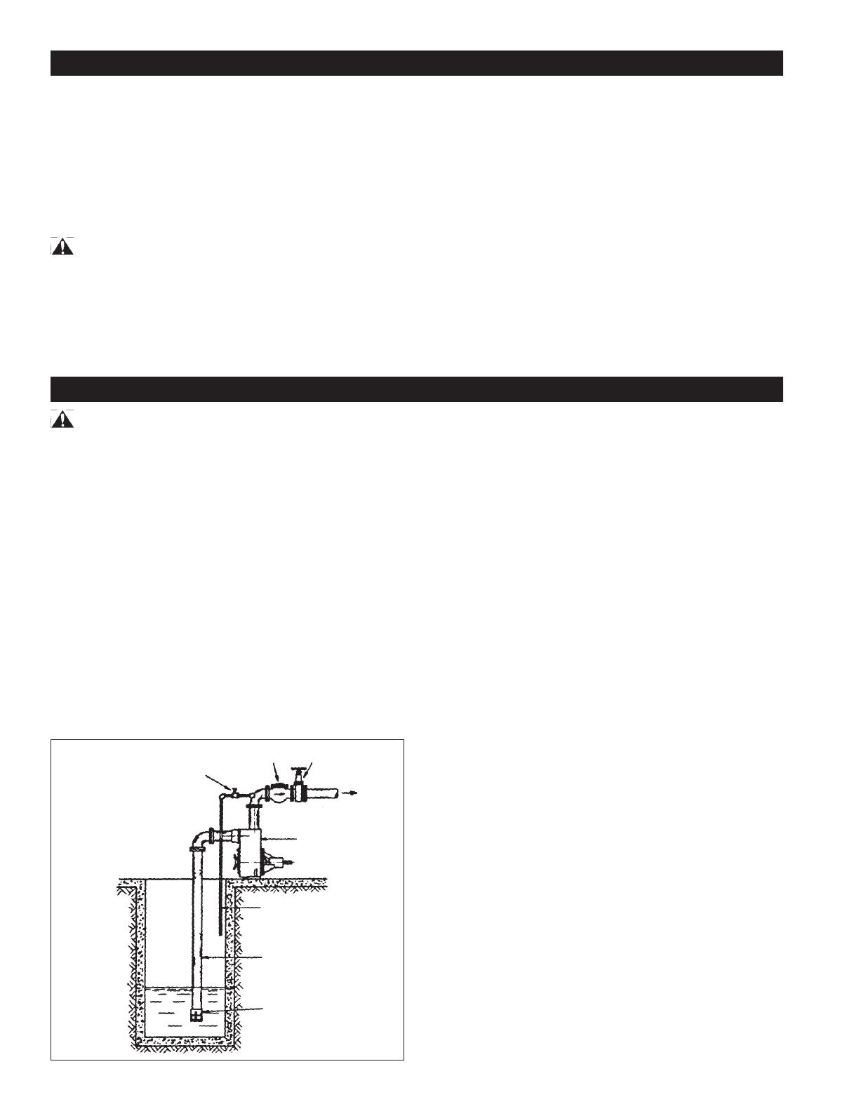
Figure 1
Gate Valve
(min. 3/4”)
Check Valve Gate Valve
Discharge
Pump
Air Bleed Line
Suction Pipe
Strainer
(c) PRIMING (PRESSURIZED SYSTEM): Place a check valve
on the discharge line of the pump. Place a pet cock or a ball
type air bleeder in place of the priming plug. Another alter-
native is to install an air bleed line with with gate valve onto
the discharge line, see Fig. 1. Open the priming port. Fill
the casing with water through the priming port. Replace the
plug or bleeder into the priming port. Open pet cock or ball
type air bleeder, and start engine. Once a continuous flow
of liquid emerges from the bleeder line, priming is complete
and the valve on pet cock can be closed off. The pump
should prime in 1/2 to 1 1 /2 minutes depending on suction
lift and the length and diameter of the suction hose. If an
exceptionally long suction line is used, the water in the cas-
ing may become overheated and vapor locked. If this oc-
curs, replace the water in the casing with cold water using
the priming and drain plugs. Continue to prime the pump.
(d) UNCLOGGING: The pump is designed to enable the
impeller and volute to be unclogged without disconnecting
either suction or discharge hoses. Simply unbolt the four
large wing nuts and remove the front cover - suction hose
still attached. Remove the volute to expose the impeller.
All parts can then be readily cleaned.
(e) DRAINING: Should the pump be subject to freezing tem-
peratures, it will be necessary to drain the pump completely.
To drain, remove the drain plug located at the bottom of the
front casing and the priming plug and make sure that the
drain hold is not choked. After all of the water has been
drained out, operate the pump for a few seconds to ensure
that the impeller is devoid of water. Make sure that the suc-
tion line is also empty.
(f) STORAGE OF PUMP: Drain liquid from pump as explained
in the “Draining” section, to prevent freezing. It is recom-
mended that a good rust inhibitor be put in the liquid end to
prevent excessive corrosion. Be sure motor is kept dry and
covered. When restoring the use of the pump, replace all
plugs and make sure all connections are tightly sealed. Af-
ter a complete check, proceed with the initial prime accord-
ing to the directions under the section “Priming”.


