
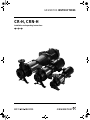
CR-H, CRN-H
GRUNDFOS INSTRUCTIONS
Installation and operating instructions

2

3
CR-H, CRN-H
Installation and operating instructions 4
Notice d’installation et d’entretien 19
Instrucciones de instalación y funcionamiento 37

4
LIMITED WARRANTY
Products manufactured by GRUNDFOS PUMPS CORPORATION (Grundfos) are warranted
to the original user only to be free of defects in material and workmanship for a period of
24 months from date of installation, but not more than 30 months from date of manufacture.
Grundfos' liability under this warranty shall be limited to repairing or replacing at Grundfos'
option, without charge, F.O.B. Grundfos' factory or authorized service station, any product
of Grundfos' manufacture. Grundfos will not be liable for any costs of removal, installation,
transportation, or any other charges which may arise in connection with a warranty claim.
Products which are sold but not manufactured by Grundfos are subject to the warranty
provided by the manufacturer of said products and not by Grundfos' warranty. Grundfos will
not be liable for damage or wear to products caused by abnormal operating conditions,
accident, abuse, misuse, unauthorized alteration or repair, or if the product was not installed
in accordance with Grundfos' printed installation and operating instructions.
To obtain service under this warranty, the defective product must be returned to the
distributor or dealer of Grundfos' products from which it was purchased together with proof
of purchase and installation date, failure date, and supporting installation data. Unless
otherwise provided, the distributor or dealer will contact Grundfos or an authorized service
station for instructions. Any defective product to be returned to Grundfos or a service station
must be sent freight prepaid; documentation supporting the warranty claim and/or a Return
Material Authorization must be included if so instructed.
GRUNDFOS WILL NOT BE LIABLE FOR ANY INCIDENTAL OR CONSEQUENTIAL
DAMAGES, LOSSES, OR EXPENSES ARISING FROM INSTALLATION, USE, OR ANY
OTHER CAUSES. THERE ARE NO EXPRESS OR IMPLIED WARRANTIES, INCLUDING
MERCHANTABILITY OR FITNESS FOR A PARTICULAR PURPOSE, WHICH EXTEND
BEYOND THOSE WARRANTIES DESCRIBED OR REFERRED TO ABOVE.
Some jurisdictions do not allow the exclusion or limitation of incidental or consequential
damages and some jurisdictions do not allow limit actions on how long implied warranties
may last. Therefore, the above limitations or exclusions may not apply to you. This warranty
gives you specific legal rights and you may also have other rights which vary from
jurisdiction to jurisdiction.

5
CONTENTS
Page
1. Symbols used in this document 5
2. Delivery 5
2.1 Check that you have the right pump 5
2.2 Check the condition of the pump 5
3. Identification 6
3.1 Type key for CR, CRN 1s, 1, 3, 5, 10, 15 and 20 H 6
3.2 Type key for CR, CRN 32, 45, 64 and 90 H 6
4. Codes 6
5. Applications 7
5.1 Pumped liquids 7
6. Operating conditions 7
6.1 Ambient temperature and altitude 7
6.2 Liquid temperature 7
6.3 Maximum permissible operating pressure and liquid
temperature for the shaft seal 7
6.4 Minimum inlet pressure – NPSHR 8
6.5 Maximum inlet pressure 8
6.6 Minimum flow rate 9
7. Technical data 9
7.1 Electrical data 9
7.2 Frequency of starts and stops 9
7.3 Dimensions and weights 9
7.4 Sound pressure level 9
8. Installation 9
8.1 Base plate 9
8.2 Foundation 9
8.3 Vibration dampening 10
8.4 Mounting on a Grundfos base plate 11
8.4.1 Bolt torques 11
8.5 Outdoor installation 11
8.6 Hot surfaces 11
8.7 Tightening torques 11
8.8 Piping 12
8.9 Recommended piping practices 12
8.10 Check valves 12
8.11 Bypass 12
8.12 Assembly of motor and pump end 12
9. Electrical connection 13
9.1 Single-phase motors 13
9.2 Three-phase motors 13
9.3 Frequency converter operation 13
10. Start-up 14
10.1 Start-up procedure 14
11. Maintenance 14
11.1 Motor inspection 14
11.2 Motor lubrication 15
11.3 Motor lubrication schedule
(for motors with grease fittings) 15
11.4 Preventative maintenance 16
12. Frost protection 16
13. Service 16
13.1 Service kits and service documentation 16
14. Start-up (air-cooled top) 17
15. Troubleshooting 18
16. Disposal 18
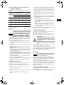
1. Symbols used in this document
2. Delivery
2.1 Check that you have the right pump
Read the pump nameplate to make sure you have received the
pump you ordered.
2.2 Check the condition of the pump
The shipping carton your pump came in is specially designed
around your pump during production to prevent damage. As a
precaution, the pump should remain in the carton until you are
ready to install it. Examine the pump for any damage that may
have occurred during shipping. Examine any other parts of the
shipment as well for any visible damage.
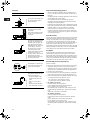
If the pump is supplied as a complete unit (motor attached to
pump end), the position of the coupling (that connects the pump
shaft to the motor shaft) is set at factory specifications. No
adjustment is required.
If the unit is supplied as a pump end only, follow the adjustment
procedures in section 8.12 Assembly of motor and pump end.
Pump without motor (CR, CRN 1s, 1, 3, 5, 10, 15 and 20 H
only)
If you purchased a pump without a motor, the shaft seal has been
set by the factory. Do not loosen the three set screws on the shaft
seal when attaching the motor.
Pump without motor (CR, CRN 32, 45, 64 and 90 H only)
If you purchased a pump without a motor, you must install the
shaft seal. The shaft seal is protected in its own sub boxing within
the pump packaging crate. Read the seal installation instructions
which are included in the pump package.
Pump without motor (all)
To protect the shaft and bearings during shipment, a shaft holder
protective device is used. This device must be removed prior to
installation of the shaft seal or motor.
Warning
Prior to installation, read these installation and
operating instructions. Installation and operation
must comply with local regulations and accepted
codes of good practice.
Warning
If these safety instructions are not observed,
it may result in personal injury!
Caution
If these safety instructions are not observed,
it may result in malfunction or damage to the
equipment!
Note
Notes or instructions that make the job easier
and ensure safe operation.
Warning
When the shipment is received, extreme care
should be exercised during unloading. Heavy
parts should be skidded to the ground if lifting
equipment is not available. It is recommended a
forklift or crane be used to unload the equipment.
Do not drop the unit, or any parts, as damage may
cause trouble in assembly and operation of the
units.
CR-H
Centrifugal pump with standard cast-iron and
304 stainless-steel construction
CRN-H
Centrifugal pump; all parts in contact with water are
316 stainless-steel construction
CRE-H
Centrifugal pump with a Grundfos MLE VFD motor
attached

6
3. Identification
3.1 Type key for CR, CRN 1s, 1, 3, 5, 10, 15 and 20 H
3.2 Type key for CR, CRN 32, 45, 64 and 90 H
4. Codes
Example CR 3-10H-X-X-X-XXXX
Pump range: CR, CRN
Rated flow rate in m
3
/h (x 5 = GPM)
Number of impellers
Code for pump version
H: Horizontal pump
Code for pipework connection
Code for materials
Code for rubber pump parts
Code for shaft seal
Example CR 32 -2 -1 H- X- X- X- XXXX
Pump range: CR, CRN
Rated flow rate in m
3
/h (x 5 = GPM)
Number of stages
Number of impellers with reduced diameter
Code for pump version
H: Horizontal pump
Code for pipework connection
Code for materials
Code for rubber pump parts
Code for shaft seal
Example H-GA-A-E-HQQE
Pump version
A Basic version*
BOversize motor
E Certificate/approval
F
CR pump for high temperatures
(air-cooled top assembly)
H Horizontal version
I Different pressure rating
J Pump with different maximum speed
K Pump with low NPSH
M Magnetic drive
N Fitted with sensor
P Undersize motor
T
Oversize motor
(two flange sizes bigger)
X Special version*
Pipework connection (suction x discharge)
GA ANSI 1.5" x 1"
GB ANSI 3" x 1.5"
GC ANSI 3" x 2"
G05 ANSI 2" x 1"
G10 ANSI 3" x 2"
G20 ANSI 3" x 1.5
G30 ANSI 3" x 1.5"
G40 ANSI 4" x 3"
G50 ANSI 3" x 1.5"
G60 ANSI 3" x 2"
G70 ANSI 4" x 3"
G22 ANSI 2" x 2"
G33 ANSI 3" x 3"
G44 ANSI 4" x 4"
Materials
A Basic version
D Carbon-graphite-filled PTFE (bearings)
G Wetted parts AISI 316
GI All parts stainless steel, wetted parts AISI 316
I Wetted parts AISI 304
II All parts stainless steel, wetted parts AISI 304
K Bronze (bearings)
S SiC bearings + PTFE neck rings
X Special version
Rubber pump parts
E EPDM
FFXM
KFFKM
VFKM
Shaft seal
H Balanced cartridge seal with O-ring
K Metal-bellows cartridge seal
O Double seal, back-to-back
P Double seal, tandem
X Special version
B Carbon, synthetic-resin-impregnated
H Cemented tungsten carbide, embedded (hybrid)
Q Silicon carbide
U Cemented tungsten carbide
X Other ceramics
E EPDM
FFXM
KFFKM
VFKM
* If a pump covers more than two pump versions, the code for
the pump version is X. X also indicates special pump versions
not listed above.
Example H-GA-A-E-HQQE

7
5. Applications
Grundfos multistage, horizontal, end-suction centrifugal pumps,
types CR-H and CRN-H, are designed for a wide range of
applications.
CR-H and CRN-H
CR-H and CRN-H pumps are suitable for liquid transfer,
circulation and pressure boosting of cold or hot clean liquids.
CRN-H
Use CRN-H pumps in systems where all parts in contact with the
liquid are made of high-grade stainless steel.
5.1 Pumped liquids
The CR-H and CRN-H are capable of pumping thin, clean, non-
flammable liquids, not containing solid particles or fibers. The
liquid must not attack the pump materials chemically.
When pumping liquids with a density and/or viscosity higher than
that of water, use motors with correspondingly higher outputs,
if required.
6. Operating conditions
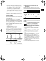
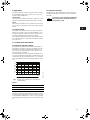
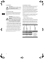
6.1 Ambient temperature and altitude
If the ambient temperature exceeds the maximum temperature
limits of the pump or the pump is installed at an altitude
exceeding the altitude values in the chart below, the motor must
not be fully loaded due to the risk of overheating.
Overheating may result from excessive ambient temperatures or
the low density and consequently low cooling effect of the air at
high altitudes. In such cases, it may be necessary to use a motor
with a higher rated output (P
2
).
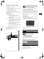
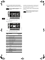
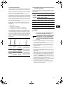
Fig. 1 Relationship between motor output (P
2
) and
ambient temperature/altitude
Legend
Example: From fig. 1 it appears that P
2
must be reduced to 88 %
when a pump with a NEMA Premium efficiency, ML motor is
installed 15584 feet above sea level. At an ambient temperature
of 167 °F, P
2
of a standard efficiency motor must be reduced to
74 % of rated output.
6.2 Liquid temperature
The tables on pages 19 and 20 state the relationship between
liquid temperature range and maximum permissible operating
pressure.
6.3 Maximum permissible operating pressure and
liquid temperature for the shaft seal
CR 1s to CR 20 H
Fig. 2 Operating range of standard shaft seals for CR 1s to
CR 20 H
CR 32 to CR 90 H
Fig. 3 Operating range of standard shaft seals for CR 32 to
CR 90 H
TM03 4272 2006
Pos. Description
1 NEMA Standard efficiency motors
2 NEMA Premium efficiency motors
Note
The maximum permissible operating pressure
and liquid temperature ranges apply to the pump
only.
60 80 100 120 140 160 180
T [°F]
50
60
70
80
90
100
[%]
P2
1
2
3280 7382 11483 15584 ft
Note
The diagrams below apply to clean water and
water containing anti-freeze liquid.
TM02 7537 1409TM04 4473 1409
Shaft
seal
Description
Max.
temperature
range
[°F]
HQQE
O-ring (cartridge) (balanced seal),
SiC/SiC, EPDM
–22 °F to +248 °F
HQQV
O-ring (cartridge) (balanced seal),
SiC/SiC, FKM
–4 °F to +194 °F
HUBE
O-ring (cartridge) (balanced seal),
TC/carbon, EPDM
+32 °F to +248 °F
HUBV
O-ring (cartridge) (balanced seal),
TC/carbon, FKM
+32 °F to +194 °F
KUBE
Bellows, metal (cartridge),
TC/carbon, EPDM
+32 °F to +248 °F
KUBV
Bellows, metal (cartridge),
TC/carbon, FKM
+32 °F to +194 °F
KUHE
Bellows, metal (cartridge),
TC/carbon with embedded TC,
EPDM
+32 °F to +194 °F
KUHV
Bellows, metal (cartridge),
TC/carbon with embedded TC,
FKM
+32 °F to +194 °F
KUUE
Bellows, metal (cartridge),
TC/TC, EPDM
–22 °F to +194 °F
KUUV
Bellows, metal (cartridge),
TC/TC, FKM
–4 °F to +194 °F
TC = tungsten carbide.
-40 0 40 80 120 160 200 240 t [°F]
0
100
200
300
400
[psi]
p
-40 -20 0 20 40 60 80 100 t [°C]
0
5
10
15
20
25
[bar]
p
HQQE
HQQV
HQQE
HQQE
-40 0 40 80 120 160 200 240 t [°F]
0
100
200
300
400
500
[psi]
p
-40 -20 0 20 40 60 80 100 t [°C]
0
5
10
15
20
25
30
[bar]
p
KUBE
HQQE / HQQV HQQE
KUUE
KUUE
KUUV
KUBE / KUBV
KUUE / KUUV
KUHE / KUHV

8
CRN-H pumps using a type H shaft seal with EPDM rubber parts,
HxxE, can be cleaned in place (CIP) with liquids up to 302 °F
(150 °C) for maximum 15 minutes.
CR-H and CRN-H pumps are not suitable for the pumping of
liquids above 248 °F (120 °C) for long periods.
6.4 Minimum inlet pressure – NPSHR
Calculation of the inlet pressure "H" is recommended in the
following cases:
• When the liquid temperature is high.
• When the flow is significantly higher than the rated flow.
• When the water is drawn from depths.
• When the water is drawn through long pipes.
• When the inlet conditions are poor.
To avoid cavitation, make sure that there is a minimum pressure
on the suction side of the pump.
The maximum suction lift "H" in feet can be calculated as follows:
H = p
b
– NPSHR – H
f
– H
v
– H
s
p
b
= Barometric pressure in feet absolute.
(Barometric pressure can be set to 33.9 feet at sea
level.)
In closed systems, p
b
indicates system pressure in
feet.
NPSHR = Net Positive Suction Head Required in feet.
(To be read from the NPSHR curve at the highest
flow the pump will be delivering.)
H
f
= Friction loss in suction pipe in feet.
(At the highest flow the pump will be delivering.)
H
v
= Vapor pressure in feet.
(To be read from the vapor pressure scale. "H
v
"
depends on the liquid temperature "T
m
".)
H
s
= Safety margin = minimum 2.0 feet.
If the "H" calculated is positive, the pump can operate at a suction
lift of maximum "H" feet.
If the "H" calculated is negative, an inlet pressure of minimum "H"
feet is required.
Fig. 4 Minimum inlet pressure – NPSHR
Always check the NPSHR value of the pump at the highest
possible flow. The NPSH curves can be found on pages 17
and 18.
6.5 Maximum inlet pressure
The table on page 21 states the maximum permissible inlet
pressure. However, the actual inlet pressure + maximum pump
pressure (at no flow) must always be lower than the maximum
operating pressures stated on pages 19 and 20.
The pumps are pressure-tested at a pressure of 1.5 times the
values stated on pages 19 and 20.
Note
The pumping of liquids above 248 °F (120 °C) may
result in periodical noise and reduced pump life.
TM04 3689 4808
Note
In order to avoid cavitation, never select a pump
whose duty point lies too far to the right on the
NPSHR curve.
66
49
39
33
26
20
16
13
10
6.6
3.3
2.6
2.0
1.3
0.9
0.7
0.3
4.9
250
230
194
212
176
158
140
122
104
86
68
50
32
Hv
(Ft)
tm
(°F)
300
270
280
82
115
148
131
98
320
340
360
370
203
259
328
413
H
f
p
b
NPSHR
H
v
H

9
6.6 Minimum flow rate
Due to the risk of overheating, do not use the pump at flows
below the minimum flow rate.
The curves below show the minimum flow rate as a percentage of
the rated flow rate in relation to the liquid temperature.
Fig. 5 Minimum flow rate
Legend
7. Technical data
7.1 Electrical data
See motor nameplate and section 9. Electrical connection.
7.2 Frequency of starts and stops
7.3 Dimensions and weights
See CR-H, CRN-H Product Guide.
7.4 Sound pressure level
See page 22.
8. Installation
The pump must be secured to a horizontal plane and solid
foundation by bolts. When installing the pump, follow the
instructions in the following sections.
8.1 Base plate
Make sure that the base plate is clean of any debris. It may also
be necessary to have the base plate coated to protect the
material.
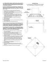
8.2 Foundation
The foundation/installation should be carried out in accordance
with the following instructions.
Grundfos recommends to install the pump on a concrete
foundation which is heavy enough to provide permanent and rigid
support to the entire pump. The foundation must be capable of
absorbing any vibration, normal strain or shock. As a rule of
thumb, the weight of the concrete foundation should be 1.5 times
the weight of the pump and base plate. The concrete foundation
must have an absolutely level and even surface.
Place the pump and base plate assembly on the foundation, and
fasten it. The base plate must be supported on the whole area.
See fig. 6.
Fig. 6 Correct installation
The foundation should be at least 3 to 6 inches longer and wider
than the base plate.
The mass of the foundation must be at least 1.5 times the total
mass of the pump and base plate assembly.
In installations where noiseless operation is particularly
important, a foundation with a mass up to 5 times that of the
pump and base plate assembly is recommended. The pump may
be fastened directly to an existing concrete floor if the floor meets
the criteria of a foundation.
To properly hold the base plate to the foundation, proper
foundation bolts are required. For proper holding of the base
through the foundation, the bolt length should extend from in the
foundation, the base height, and 0.25" - 0.50" above the nut.
These foundation bolts are embedded in the concrete floor or
foundation, and should be positioned according to the bolt
manufacturer’s instructions. To assist in the proper location of the
bolts, a template can be formed. The bolt locations should be
double-checked with drawings and base.
TM02 7538 3703
Curves Description
CR-H with standard top
CR-H with air-cooled top
Caution
Never operate the pump against a closed
discharge valve.
Motor sizes
Maximum number of starts per hour
Grundfos ML Baldor
0.33 to 5.0 hp 200 20
7.5 to 15 hp 100 15
20 to 100 hp 40 10
t [°F]
0
10
20
30
Qmin
[%]
40 60 80 100 120 140 160 180
t [°C]
140 176 212 248 284 320 356104
Note
The pump should be placed as close to the liquid
source as possible. Adequate space for
operation and maintenance should be taken into
consideration.
TM04 3730 4908

10
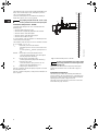
Bolt sleeves can be used to allow final positioning of the bolts.
The sleeves are a minimum of 3 times larger than the bolt, and
have a length of at least 10 times the diameter. Figure 7 (pos. b)
shows the foundation bolt and the bolt sleeve in which it is
installed.
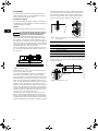
Fig. 7 Bolt in position (pos. a) and bolt sleeve detail (pos. b)
When the foundation bolts are in position, the pump can be
placed on the foundation. The base plate can now be leveled
using shims, if necessary, so that it is completely horizontal.
See fig. 8.
Fig. 8 Alignment with shims
8.3 Vibration dampening
If vibration dampers are used, they must be installed under the
foundation.
Pumps with motor size ≤ 40 hp (30 kW) can use vibration
dampers as shown in fig. 9.
For pumps with motor sizes ≥ 50 hp (37 kW), use a vibration
damper as shown in fig. 10.
Fig. 9 Pump on vibration dampers
Fig. 10 Pump on vibration damper
TM03 4589 2206 - TM04 3731 4908
Pos. Description
1Nut
2 Washer
3 Base plate
4 Bolt sleeve
5 Non-bonding fill
6 Concrete
TM03 4588 2206
1
2
3
4
5
6
ba
Shims
TM04 3732 4908TM04 3733 4908
Vibration
dampers
Vibration
damper

11
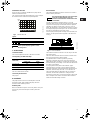
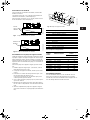
8.4 Mounting on a Grundfos base plate
Check that the Grundfos base plate will fit to your pump model.
The base plate is made with adjustable motor mount sliders to
accommodate a range of Grundfos CR-H pumps. See fig. 11.
The sliders make it possible to separate the motor from the pump
end if service is required.
To mount the pump to the base plate, proceed as follows:
1. Install the base plate (pos. 1) on the foundation in accordance
with the instructions in sections 8.1 to 8.3.
2. If the base plate is grouted, allow grouting sufficient time to
dry.
3. Set the motor mount sliders (pos. 3) in position on the base
plate rails (pos. 2).
Make sure the 1/4" bolts are loose so that the sliders can slide
easily.
4. With a hoist, lower the pump until it is almost on the sliders.
5. Make all necessary adjustments to line up all bolts and bolt
holes and hand-tighten all bolts.
6. Lower the pump completely onto the base plate, and tighten
all bolts to the proper torque (see bolt table).
Fig. 11 Grundfos base plate
8.4.1 Bolt torques
8.5 Outdoor installation
When installed outdoors, it is recommended to provide the motor
with a rain cover or other shelter. On Grundfos ML motors, it is
also recommended to open the bottom most drain hole in the
motor flange.
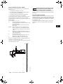
8.6 Hot surfaces
Figure 12 shows which pump parts get the same temperature as
the pumped liquid.
Fig. 12 Potentially hot surfaces on a CR-H and CRN-H pump
8.7 Tightening torques
The table below shows the recommended tightening torques for
bolts in flanges.
TM04 4123 0809
Pos. Description
1 Base plate
2 Base plate rail
3 Motor mount slider
4 Motor mounting bolt
5 1/4" bolt
6 Grouting hole
7 5/8" bolt
8 Volute mounting pad
9 Hole for lifting hook
10 ANSI mounting hole
Motor frame Bolt size
Bolt torque
[ft-lbs] [Nm]
N/A 1/4" - 20 UNC 7 9.5
56C 5/16" - 18 UNC 14 19
182/184TC 3/8" - 16 UNC 25 34
213/215TC 3/8" - 16 UNC 25 34
254/256TC 1/2" - 13 UNC 62 84
284/286TSC 1/2" - 13 UNC 62 84
324/326TSC 5/8" - 11 UNC 109 148
364/365TSC 5/8" - 11 UNC 109 148
* Torques are based on SAE Grade 5 bolts.
Warning
When pumping hot liquids, care should be taken
to ensure that persons cannot accidentally come
into contact with hot surfaces.
TM04 3734 4908
CR, CRN-H
Torque
[ft-lbs] [Nm]
1s to 5 37-45 50-60
10 to 20 45-52 60-70
32 to 90 52-59 70-80
Pump head
Pump sleeve
Volute

12
8.8 Piping 8.9 Recommended piping practices
• Whenever possible, avoid fittings that cause high pressure
loss, such as elbows or branch tees directly on either side of
the pump.
• The piping should be adequately supported to reduce thermal
and mechanical stress on the pump.
• Good installation practice recommends the system be
thoroughly cleaned and flushed of all foreign materials and
sediment prior to pump installation.
• Furthermore, the pump should never be installed at the lowest
point of the system due to the natural accumulation of dirt and
sediment. If there is excessive sediment or suspended
particles present, it is advisable to use a strainer or filter.
• Grundfos recommends that pressure gauges be installed on
suction and discharge volute ports or in pipes to check pump
and system performance.
8.10 Check valves
A check valve may be required on the discharge side of the pump
to prevent the pump’s inlet pressure from being exceeded. For
example, if a pump with no check valve is stopped because there
is no demand on the system (all valves are closed), the high
system pressure on the discharge side of the pump will "find" its
way back to the inlet of the pump. If the system pressure is
greater than the pump’s maximum inlet pressure rating, the limits
of the pump will be exceeded and a check valve needs to be fitted
on the discharge side of the pump to prevent this condition.
8.11 Bypass
A bypass should be installed in the discharge pipe if there is
any risk that the pump may operate against a closed valve in
the discharge pipe. Flow through the pump is required to ensure
that adequate cooling and lubrication of the pump is maintained.
See fig. 5 for minimum flow rates. Elbows should be a minimum
of 12 inches from the discharge port to prevent erosion.
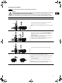
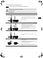
8.12 Assembly of motor and pump end
Proceed as follows:
1. Remove the key from the motor shaft, if present, and discard.
2. Thoroughly clean the surfaces of the motor and pump end
mounting flange. The motor and shaft must be clean of all oil/
grease and other contaminants where the coupling attaches.
3. Set the motor on the pump end.
4. Place the terminal box in the desired position by rotating the
motor so that the motor feet are in line with the pump foot.
5. Insert the mounting bolts. Then tighten diagonally and evenly:
– for 3/8" bolts (1/2 to 2 hp), tighten to 17 ft- b
– for 1/2" bolts (3 to 40 hp), tighten to 30 ft-lb
– for 5/8" bolts (50 to 60 hp), tighten to 59 ft-lb.
6. CR, CRN 1s, 1, 3 and 5 H
Insert the shaft pin into the shaft hole.
Fit the coupling halves onto the shaft and shaft pin.
Fit the coupling screws and leave loose.
Check that the gaps on either side of the coupling are even
and that the motor shaft keyway is centered in the coupling
half.
Tighten the screws to the correct torque.
CR, CRN 10, 15 and 20 H
Insert the shaft pin into the shaft hole.
Insert the plastic shaft seal spacer beneath the shaft seal
collar.
Fit the coupling halves onto the shaft and shaft pin.
Fit the coupling screws and leave loose.
Check that the gaps on either side of the coupling are even
and that the motor shaft keyway is centered in the coupling
half.
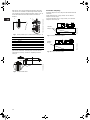
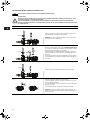
Step Action
1
TM04 3736 4908
The arrows in the drawing show
the direction of flow of liquid
through the pump.
2
TM04 3737 4908
The pump must be installed
horizontally.
Ensure that an adequate supply
of cool air reaches the motor
cooling fan.
3
TM04 3738 4908
To minimize possible noise from
the pump, it is advisable to fit
expansion joints on either side
of the pump. The foundation/
installation must be carried out
as described in section 8.2.
Fit isolation valves on either
side of the pump to avoid
draining the system if the pump
needs to be removed for
cleaning, repair or replacement.
Always protect the pump
against backflow by means of a
check valve (foot valve).
4
TM02 0114 3800
Install the pipes so that air locks
are avoided, especially on the
suction side of the pump.
5
TM04 3739 4908
Fit a vacuum valve close to the
pump if the installation has one
of these characteristics:
• The discharge pipe slopes
downwards away from the
pump.
• There is a risk of siphon
effect.
• Protection against backflow
of unclean liquids is needed.

13
Tighten the screws to the correct torque.
Remove the plastic shaft seal spacer, and hang it on the inside
of the coupling guard.
CR, CRN 32, 45, 64 and 90 H
Place the plastic adjustment fork under the cartridge seal
collar.
Fit the coupling on the shaft so that the top of the pump shaft
is flush with the bottom of the clearance chamber in the
coupling.
Lubricate the coupling screws with an anti-seize and
lubricating compound.
Tighten the coupling screws (finger-tight) while keeping the
coupling separation equal on both sides and the motor shaft
keyway centered in the coupling half.
When the screws are tight enough to keep the couplings in
place, then tighten the screws diagonally and evenly.
Tighten the coupling screws to 62 ft-lbs (84 Nm).
Remove the adjustment fork from under the cartridge seal
collar, and replace it to the storage location.
7. Check to see that the gaps between the coupling halves are
equal. Loosen and readjust, if necessary.
8. Be certain the pump shaft can be rotated by hand. If the shaft
cannot be rotated or it binds, disassemble and check for
misalignment.
9. Prime the pump.
10.Follow the wiring diagram on the motor nameplate for the
correct motor wiring combination which matches your supply
voltage. Once this has been confirmed, reconnect the power
supply wiring to the motor.
11.Check the direction of rotation by bump-starting the motor.
Rotation must be left to right (counter-clockwise) when looking
directly at the coupling from the motor end.
12.Switch off the power supply, and refit the coupling guards.
After the coupling guards have been installed, the power
supply can be switched on again.
9. Electrical connection
The electrical connection should be carried out by an authorized
electrician in accordance with local regulations.
Field wiring
Wire sizes should be based on the current-carrying properties of
a conductor as required by the latest edition of the National
Electrical Code or local regulations. Direct on line (DOL) starting
is approved due to the extremely fast run-up time of the motor
and the low moment of inertia of the pump and motor. If DOL
starting is not acceptable and reduced starting current is required,
an autotransformer, resistance starter or soft starter should be
used. It is suggested that a fused disconnect be used for each
pump where service and standby pumps are installed.
Recommendation
We recommend the use of flexible conduit. Flexible conduit
allows movement of the motor on the base plate rails if service is
required.
The operating voltage and frequency are marked on the motor
nameplate. Make sure that the motor is suitable for the power
supply on which it will be used and the motor terminal connection
is correct. You will find a wiring diagram in the terminal box.
9.1 Single-phase motors
With the exception of 10 hp motors which require external
protection, single-phase motors for CR pumps provided by
Grundfos are multi-voltage, squirrel-cage induction motors with
built-in thermal protection.
9.2 Three-phase motors
CR pumps with three-phase motors must be used with the proper
size and type of motor starter to ensure the motor is protected
against damage from low voltage, phase failure, current
imbalance and overloads. A properly sized starter with manual
reset and ambient-compensated extra quick trip in all three legs
should be used. The overload should be sized and adjusted to
the service factor current rating of the motor.
Under no circumstances should the overloads be set to a higher
value than the service factor current shown on the motor
nameplate. This will void the warranty. Overloads for
autotransformers and resistance starters should be sized in
accordance with the recommendations of the manufacturer.
Three-phase MLE motors (CRE-H pumps) require only fuses as a
circuit breaker. They do not require a motor starter. Check for
phase imbalance.
9.3 Frequency converter operation
Motors supplied by Grundfos
All three-phase motors supplied by Grundfos can be connected to
a frequency converter. The frequency converter must be
configured for variable-torque operation.
Depending on the frequency converter type, this may cause
increased acoustic noise from the motor. Furthermore, it may
cause the motor to be exposed to detrimental voltage peaks.
Warning
Before removing the terminal box cover and
before removing/dismantling the pump, make
sure that the power supply has been switched off.
The pump must be connected to the power
supply using a supply disconnecting device.
The safe operation of this pump requires that it
be grounded in accordance with the National
Electrical Code and local governing codes or
regulations. Connect the ground wire to the
grounding screw in the terminal box and then to
the acceptable grounding point.
Caution
The need for an emergency stop should be
decided by the user.
Note
Standard allowable phase imbalance difference
is 5 % (voltage and current).
Caution
Grundfos motors, types ML 71 and ML 80, for
supply voltages up to and including 460 V are
without phase insulation (see motor nameplate).
They must be protected against voltage peaks
above 650 V (peak value) between the supply
terminals.

14
We recommend to protect all other motors against voltage peaks
higher than 1200 V by 2000 V/µsec.
The above disturbances, i.e. both increased acoustic noise and
detrimental voltage peaks, can be eliminated by fitting an LC filter
between the frequency converter and the motor.
For further information, please contact the frequency converter or
motor supplier.
Other motor makes than those supplied by Grundfos
Please contact the motor manufacturer.
10. Start-up
10.1 Start-up procedure
1. Make sure the power supply is switched off.
2. Check to make sure the pump has been primed. See
procedure below.
Priming procedure
To prime the pump in a closed system or an open system where
the water source is above the pump, proceed as follows:
• Close the pump isolation valve(s), and open the priming plug
on the pump head.
• Gradually open the isolation valve in the suction pipe until a
steady stream of airless water runs out the priming port.
• Close the priming plug and securely tighten. Completely open
the isolation valves.
In open systems where the water level is below the pump inlet,
the suction pipe and pump must be filled and vented of air before
starting the pump.
• Close the discharge isolation valve, and remove the priming
plug.
• Pour water through the priming hole until the suction pipe and
pump are completely filled with water. If the suction pipe does
not slope downwards away from the pump towards the water
level, the air must be purged while being filled.
• Replace the priming plug and securely tighten.
For pumps with air-cooled top, see page 17.
For all systems, proceed as follows:
3. Remove the coupling guard, and rotate the pump shaft by
hand to be certain it turns freely.
4. Verify that the electrical connections are in accordance with
the wiring diagram on the motor.
5. Switch on the power supply momentarily and observe the
direction of rotation. When viewed from the motor end, the
pump should rotate counter-clockwise.
6. To reverse the direction of rotation, first switch off the power
supply.
7. On three-phase motors, interchange any two power leads at
the load side of the starter.
On single-phase motors, see wiring diagram on the
nameplate. Change wiring as required.
8. Switch on the power supply, and again check for proper motor
rotation. Once rotation has been verified, switch off the power
supply again.
9. Do not attempt to refit the coupling guards with the motor
energized. Replace the coupling guard if the rotation is
correct. After the guards are in place, the power supply can be
switched on again.
Operating parameters
CR multistage centrifugal pumps installed in accordance with
these instructions and sized for correct performance will operate
efficiently and provide years of service.
The pumps are water-lubricated and do not require any external
lubrication or inspection.
The motors may require periodic lubrication as noted in section
11. Maintenance.
Under no circumstances should the pump be operated for any
prolonged periods of time without flow through the pump. This
can result in motor and pump damage due to overheating.
A properly sized relief valve should be installed to allow sufficient
water to circulate through the pump to provide adequate cooling
and lubrication of the pump bearings and seals.
Pump cycling
Pump cycling should be checked to ensure the pump is not
starting more often than stated in the table in section
7.2 Frequency of starts and stops.
Rapid cycling is a major cause of premature motor failure due to
increased heat build-up in the motor. If necessary, adjust
controllers to reduce the frequency of starts and stops.
11. Maintenance
Pump bearings and shaft seal are maintenance-free.
11.1 Motor inspection
Inspect the motor at regular intervals, approximately every
500 hours of operation or every three months, whichever occurs
first. Keep the motor clean and the ventilation openings clear.
The following steps should be performed at each inspection:
Caution
Do not start the pump until it has been filled with
liquid and vented. If the pump runs dry, the pump
bearings and the shaft seal may be damaged.
Warning
Pay attention to the direction of the vent hole, and
take care to ensure that the escaping water does
not cause injury to persons or damage to the
motor or other components.
In hot-water installations, pay special attention to
the risk of injury caused by scalding hot water.
Caution
Do not start the pump before priming or venting
the pump (step 2).
Never operate the pump dry.
Note
Motors should not be run unloaded or uncoupled
from the pump at any time. Damage to the motor
bearings may occur.
Warning
Before starting work on the pump, make sure that
all power supplies to the pump have been
switched off and that they cannot be accidentally
switched on.
Warning
Do not touch electrical connections before you
first ensure that the power supply has been
disconnected.
Electrical shock can cause serious or fatal injury.
Only qualified personnel should attempt
installation, operation and maintenance of this
equipment.

15
1. Check that the motor is clean. Check that the interior and
exterior of the motor is free of dirt, oil, grease, water, etc. Oily
vapor, paper, pulp, textile lint, etc. can accumulate and block
motor ventilation. If the motor is not properly ventilated,
overheating can occur and cause early motor failure.
2. Use an ohmmeter ("Megger") periodically to ensure that the
integrity of the winding insulation has been maintained.
Record the ohmmeter readings. Immediately investigate any
significant drop in insulation resistance.
3. Check all electrical connectors to be sure that they are tight.
In the case of seasonal operation (motor is idle for more than
six months of the year), it is recommended to grease the motor
when the pump is taken out of operation.
11.2 Motor lubrication
Electric motors are pre-lubricated from factory and do not require
additional lubrication before start-up.
Motors without external grease fittings have sealed bearings that
cannot be relubricated.
Motors with grease fittings should only be lubricated with
approved types of grease (see table below). Do not overgrease
the bearings. Overgreasing will cause increased bearing heat and
may result in bearing/motor failure. Do not mix petroleum grease
and silicon grease in motor bearings.
Bearing grease will lose its lubricating ability over time, not
suddenly. The lubricating ability of a grease (over time) depends
primarily on the following:
• The type of grease.
• The size of the bearings.
• The speed at which the bearings operate.
• The severity of the operating conditions.
Good results can be obtained if the following recommendations
are used in your maintenance program. It should also be noted
that pumps with more stages, pumps running to the left of the
performance curve and certain pump ranges may have higher
thrust loads. Pumps with high thrust loads should be greased
according to the next service interval level.
11.3 Motor lubrication schedule (for motors with
grease fittings)
New motors that have been stored for a year or more should be
regreased.
Procedure
1. Clean all grease fittings. If the motor does not have grease
fittings, the bearings are sealed and cannot be greased
externally.
2. If the motor is equipped with a grease outlet plug, remove it.
This will allow the old grease to be displaced by the new
grease.
3. If the motor is stopped, add the recommended amount of
grease.
If the motor is to be greased while running, a slightly greater
quantity of grease will have to be added.
Note: If new grease does not appear at the shaft hole or
grease outlet plug, the outlet passage may be blocked. At the
next service interval, the bearings must be repacked.
Add grease slowly taking approximately one minute until new
grease appears at the shaft hole in the end plate or grease
outlet plug.
Never add more than 1-1/2 times the amount of grease shown
in the lubrication schedule.
4. For motors equipped with a grease outlet plug, let the motor
run for 20 minutes before replacing the plug.
Severity of
service
Maximum ambient
temperature
Environment
Approved types
of grease
Standard
+104 °F
(+40 °C)
Clean,
little corrosion
Grundfos motors
are greased for life
or will have the
grease type on the
nameplate.
Baldor motors are
greased with
Polyrex EM (Exxon
Mobile).
Severe
+122 °F
(+50 °C)
Moderate dirt,
corrosion
Extreme
> +122 °F
(+50 °C)
or class H
insulation
Severe dirt,
abrasive dust,
corrosion
NEMA/(IEC)
Frame size
Service interval Grease to add
Standard Severe Extreme Weight Volume
hrs hrs hrs OZ./g In
3
/tsp
Up through
210 (132)
5500 2750 550 0.3/8.4 0.6/2
Over 210
through 280
(180)
3600 1800 360
0.61/
17.4*
1.2/3.9*
Over 280 up
through 360
(225)
2200 1100 220
0.81/
23.1*
1.5/5.2*
Over 360
(225)
2200 1100 220
2.12/
60.0*
4.1/
13.4*
* The grease outlet plug must be removed before adding new
grease.
Caution
To avoid damage to motor bearings, grease must
be kept free of dirt. For an extremely dirty
environment, contact Grundfos, the motor
manufacturer or an authorized service center for
additional information. Mixing dissimilar grease
is not recommended.

16
11.4 Preventative maintenance
At regular intervals, depending on the conditions and time of
operation, the following checks should be made:
• Pump meets required performance and is operating smoothly
and quietly.
• There are no leaks, particularly at the shaft seal.
• The motor is not overloading.
• Remove and clean all strainers or filters in the system.
• Verify the tripping of the motor overload protection.
• Check the operation of all controllers. Check unit control
cycling twice and adjust, if necessary.
• If the pump is not operated for unusually long periods, the unit
should be maintained in accordance with these instructions.
In addition, if the pump is not drained, the pump shaft should
be manually rotated or run for short periods of time at monthly
intervals.
• To extend the pump life in severe duty applications, consider
performing one of the following actions:
– Drain the pump after each use.
– Flush the pump, through system, with water or other fluid
that is compatible with the pump materials and process
liquid.
– Disassemble the pump liquid components, and thoroughly
rinse or wash them with water or other fluid that is
compatible with the pump materials and process liquid.
If the pump fails to operate or there is a loss of performance, see
section 15. Troubleshooting.
12. Frost protection
Pumps which are not being used during periods of frost should be
drained to avoid damage.
Drain the pump by loosening the vent screw in the pump head
and by removing the drain plug from the base.
Do not tighten the vent screw and do not replace the drain plug
until the pump is to be used again.
Always replace the drain plug with the original or exact
replacement. Do not replace with a standard plug. Internal
recirculation will occur, reducing the output pressure and flow.
13. Service
If Grundfos is requested to service the pump, Grundfos must be
contacted with details about the pumped liquid, etc. before the
pump is returned for service. Otherwise Grundfos can refuse to
accept the pump for service.
Possible costs of returning the pump are to be paid by the
customer.
However, any application for service (no matter to whom it may
be made) must include details about the pumped liquid if the
pump has been used for liquids which are toxic or injurious to
health.
13.1 Service kits and service documentation
Service kits, Service instructions and Service videos for CR-H
and CRN-H,
see www.grundfos.com (WebCAPS) or WinCAPS.
Warning
Pay attention to the direction of the vent hole and
take care to ensure that the escaping water does
not cause injury to persons or damage to the
motor or other components.
In hot-water installations, pay special attention to
the risk of injury caused by scalding hot water.
Note
If a pump has been used for a liquid which is
toxic or injurious to health, the pump will be
classified as contaminated.

17
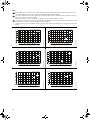
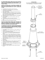
14. Start-up (air-cooled top)
Note
Do not start the pump until it has been filled with liquid and vented.
Warning
Pay attention to the direction of the vent hole, and take care to ensure that the escaping liquid does not cause injury
to persons or damage to the motor or other components.
In hot-liquid installations, special attention should be paid to the risk of injury caused by scalding hot liquid.
It is recommended to connect a drain pipe to the 1/2" air vent in order to lead the hot water/steam to a safe place.
Step Action
1
TM04 4280 1109
Close the isolation valve on the discharge side, and open the
isolation valve on the suction side of the pump.
Note: The air-cooled top should only be started up with cold liquid.
2
TM04 4282 1109
Remove the air vent pipe (2) from the air-cooled chamber (1) by
loosening the lock nut and unscrewing the pipe. Slowly fill the
chamber with liquid.
When the chamber is completely filled with liquid, replace the air
vent pipe, and tighten the lock nut securely.
It may be necessary to apply new PTFE tape to the pipe threads
and pipe dope to the chamber threads to seal.
3
TM04 4283 1109
Open the isolation valve on the discharge side of the pump.
4
TM04 4284 1109 - TM04 4285 1109
Start the pump, and check the direction of rotation.
See the correct direction of rotation of the pump on the motor fan
cover.
If the direction of rotation is wrong, interchange any two of the
incoming supply wires.
After 3 to 5 minutes, the air vent has been filled with liquid.
Note: During start-up of a cold pump with hot liquid, it is normal
that a few drops of liquid are leaking from the sleeve.
Closed
Open
1
2
Closed
Open
Open
Open

18
15. Troubleshooting
16. Disposal
This product or parts of it must be disposed of in an
environmentally sound way:
1. Use the public or private waste collection service.
2. If this is not possible, dispose of the product according to local
regulations. Grundfos recommends that the products are
recycled whenever possible.
Warning
Before removing the terminal box cover and before removing/dismantling the pump, make sure that the power
supply has been switched off and that it cannot be accidentally switched on.
Fault Cause Remedy
1. Motor does not run
when started.
a) Supply failure. Connect the power supply.
b) Fuses are blown. Replace fuses.
c) Motor-protective circuit breaker has tripped out. Reactivate the motor-protective circuit breaker.
d) Thermal protection has tripped out. Reactivate the thermal protection.
e) Main contacts in motor-protective circuit breaker
are not making contact or the coil is faulty.
Replace contacts or magnetic coil.
f) Control circuit is defective. Repair the control circuit.
g) Motor is defective. Replace the motor.
2. Motor-protective circuit
breaker trips out
immediately when
supply is switched on.
a) One fuse/automatic circuit breaker is blown. Replace the fuse/cut in the circuit breaker.
b) Contacts in motor-protective circuit breaker are
faulty.
Replace motor-protective circuit breaker contacts.
c) Cable connection is loose or faulty. Fasten or replace the cable connection.
d) Motor winding is defective. Replace the motor.
e) Pump mechanically blocked. Remove the mechanical blocking of the pump.
f) Motor-protective circuit breaker setting is too
low.
Set the motor-protective circuit breaker correctly.
3. Motor-protective circuit
breaker trips out
occasionally.
a) Motor-protective circuit breaker setting is too
low.
Set the motor-protective circuit breaker correctly.
b) Low voltage at peak times. Check the power supply.
4. Motor-protective circuit
breaker has not tripped
out but the pump does
not run.
a) Check 1 a), b), d), e) and f).
5. Pump performance not
constant.
a) Pump inlet pressure is too low (cavitation). Check the suction conditions.
b) Suction pipe/pump partly blocked by impurities. Clean the suction pipe/pump.
c) Pump draws in air. Check the suction conditions.
6. Pump runs but gives no
water.
a) Suction pipe/pump blocked by impurities. Clean the suction pipe/pump.
b) Foot or check valve blocked in closed position. Repair the foot or check valve.
c) Leakage in suction pipe. Repair the suction pipe.
d) Air in suction pipe or pump. Check the suction conditions.
e) Motor runs in the wrong direction of rotation. Change the direction of rotation of the motor.
7. Pump runs backwards
when switched off.
a) Leakage in suction pipe. Repair the suction pipe.
b) Foot or check valve is defective. Repair the foot or check valve.
8. Leakage in shaft seal. a) Shaft seal is defective. Replace the shaft seal.
9. Noise. a) Cavitation. Check the suction conditions.
b) Pump does not rotate freely (frictional
resistance) because of incorrect pump shaft
position.
Adjust the pump shaft/shaft seal setting.
See Service instructions.
c) Frequency converter operation. See section 9.3 Frequency converter operation.
Subject to alterations.

19
GARANTIE LIMITÉE
Les produits fabriqués par GRUNDFOS PUMPS CORPORATION (Grundfos) sont couverts
par une garantie à l'utilisateur initial à l'effet qu'ils sont exempts de vices attribuables aux
matériaux et à la fabrication pour une période de 24 mois après la date d'installation, mais
sans excéder une période de 30 mois après la date de fabrication. Selon les termes de cette
garantie, la responsabilité de Grundfos se limitera à réparer ou à remplacer sans frais, à la
discrétion de Grundfos et FAB de l'usine de Grundfos ou d'un poste de service autorisé, tout
produit provenant de l'usine de Grundfos. Grundfos ne sera pas responsable des frais
d'enlèvement, d'installation, de transport, ou de tous les autres frais pouvant être encourus
dans le cadre d'une demande d'indemnité concernant la garantie. Les produits vendus, mais
qui ne sont pas fabriqués par Grundfos, sont couverts par la garantie offerte par les fabri-
cants de ces produits, et ils ne sont pas couverts par la garantie de Grundfos. Grundfos ne
sera pas responsable de la détérioration des produits ou des produits endommagés dans les
cas suivants : conditions d'utilisation anormales, accidents, abus, mauvais usage, modifica-
tion ou réparation non autorisée, ou lorsque le produit n'a pas été installé conformément aux
instructions écrites de Grundfos concernant l'installation et l'exploitation.
Pour obtenir un service selon les termes de cette garantie, vous devez retourner le produit
défectueux au distributeur ou au fournisseur de produits Grundfos qui vous a vendu le
produit, incluant la preuve d'achat et la date d'installation, la date de la défaillance, et les
informations concernant l'installation. Sauf disposition contraire, le distributeur ou le
fournisseur contactera Grundfos ou un poste de service autorisé pour obtenir les
instructions. Tout produit défectueux doit être retourné "fret payé à l'avance" à Grundfos ou
à un poste de service. Les documents décrivant la demande d'indemnité aux termes de la
garantie et/ou une autorisation de retour de marchandise doivent être inclus si exigé.
GRUNDFOS NE SERA PAS RESPONSABLE DES DOMMAGES INDIRECTS OU
CONSÉCUTIFS, DES PERTES, OU DES FRAIS DÉCOULANT DE L'INSTALLATION,
L'UTILISATION, OU DE TOUTE AUTRE CAUSE. IL N'EXISTE AUCUNE GARANTIE
EXPRESSE OU IMPLICITE, INCLUANT LA QUALITÉ MARCHANDE OU L'ADAPTATION À
UNE FIN PARTICULIÈRE, QUI OUTREPASSE LES GARANTIES DÉCRITES OU
RÉFÉRENCÉES CI-DESSUS.
Certaines juridictions ne permettent pas l'exclusion ou la limitation des dommages indirects
ou consécutifs, et certaines juridictions ne permettent pas de limiter la durée des garanties
implicites. Il est donc possible que les limitations ou que les exclusions mentionnées
précédemment ne s'appliquent pas à vous. Cette garantie vous accorde des droits légaux
spécifiques, et vous pouvez également avoir d'autres droits qui varient d'une juridiction à
l'autre.

20
SOMMAIRE
Page
1. Symboles utilisés dans cette notice 20
2. Livraison 21
2.1 Vérifier que vous avez reçu la bonne pompe 21
2.2 Vérifier l'état de la pompe 21
3. Identification 22
3.1 Désignation des pompes
CR, CRN 1s, 1, 3, 5, 10, 15 et 20 H 22
3.2 Désignation des pompes CR,
CRN 32, 45, 64 et 90 H 22
4. Codes 22
5. Applications 23
5.1 Liquides pompés 23
6. Conditions de fonctionnement 23
6.1 Température ambiante et altitude 23
6.2 Température du liquide 23
6.3 Pression de service maximale admissible
et température du liquide pour le joint d'arbre 24
6.4 Pression d’entrée minimale – NPSHR 25
6.5 Pression d'admission maximale 25
6.6 Débit minimum 25
7. Caractéristiques techniques 25
7.1 Caractéristiques électriques 25
7.2 Fréquence des démarrages et des arrêts 25
7.3 Dimensions et poids 25
7.4 Niveau de pression sonore 25
8. Installation 26
8.1 Plaque de support 26
8.2 Base 26
8.3 Amortisseur de vibrations 27
8.4 Installation sur une plaque de support Grundfos 27
8.4.1 Couples de serrage boulons 27
8.5 Installation extérieure 27
8.6 Surfaces chaudes 28
8.7 Couples de serrage 28
8.8 Tuyauterie 28
8.9 Recommandations concernant la tuyauterie 29
8.10 Clapets anti-retour 29
8.11 Dispositif de dérivation 29
8.12 Assemblage du moteur et de l'extrémité de la pompe 29
9. Branchement électrique 30
9.1 Moteurs monophasés 30
9.2 Moteurs triphasés 30
9.3 Fonctionnement du convertisseur de fréquence 30
10. Démarrage 30
10.1 Procédure de démarrage 31
11. Maintenance 32
11.1 Inspection du moteur 32
11.2 Lubrification du moteur 32
11.3 Plan de lubrification moteur (pour moteurs
à embouts de lubrification) 33
11.4 Maintenance préventive 33
12. Protection contre le gel 33
13. Révision 33
13.1 Kits et documention d'entretien 33
14. Démarrage (partie supérieure refroidie à l'air) 34
15. Détection des pannes 35
16. Mise au rebut 36
1. Symboles utilisés dans cette notice
Avertissement
Avant d'entamer les opérations d'installation,
étudier avec attention la présente notice d'instal-
lation et de fonctionnement. L'installation et le
fonctionnement doivent être conformes aux
réglementations locales et faire l'objet d'une
bonne utilisation.
Avertissement
Si ces instructions de sécurité ne sont pas
observées, il peut en résulter des dommages
corporels !
Précautions
Si ces instructions ne sont pas respectées, cela
peut entrainer un dysfonctionnement ou des
dégats sur le matériel !
Nota
Ces instructions rendent le travail plus facile et
assurent un fonctionnement fiable.
La page est en cours de chargement...
La page est en cours de chargement...
La page est en cours de chargement...
La page est en cours de chargement...
La page est en cours de chargement...
La page est en cours de chargement...
La page est en cours de chargement...
La page est en cours de chargement...
La page est en cours de chargement...
La page est en cours de chargement...
La page est en cours de chargement...
La page est en cours de chargement...
La page est en cours de chargement...
La page est en cours de chargement...
La page est en cours de chargement...
La page est en cours de chargement...
La page est en cours de chargement...
La page est en cours de chargement...
La page est en cours de chargement...
La page est en cours de chargement...
La page est en cours de chargement...
La page est en cours de chargement...
La page est en cours de chargement...
La page est en cours de chargement...
La page est en cours de chargement...
La page est en cours de chargement...
La page est en cours de chargement...
La page est en cours de chargement...
La page est en cours de chargement...
La page est en cours de chargement...
La page est en cours de chargement...
La page est en cours de chargement...
La page est en cours de chargement...
La page est en cours de chargement...
La page est en cours de chargement...
La page est en cours de chargement...
La page est en cours de chargement...
La page est en cours de chargement...
La page est en cours de chargement...
La page est en cours de chargement...
La page est en cours de chargement...
La page est en cours de chargement...
La page est en cours de chargement...
La page est en cours de chargement...
-
 1
1
-
 2
2
-
 3
3
-
 4
4
-
 5
5
-
 6
6
-
 7
7
-
 8
8
-
 9
9
-
 10
10
-
 11
11
-
 12
12
-
 13
13
-
 14
14
-
 15
15
-
 16
16
-
 17
17
-
 18
18
-
 19
19
-
 20
20
-
 21
21
-
 22
22
-
 23
23
-
 24
24
-
 25
25
-
 26
26
-
 27
27
-
 28
28
-
 29
29
-
 30
30
-
 31
31
-
 32
32
-
 33
33
-
 34
34
-
 35
35
-
 36
36
-
 37
37
-
 38
38
-
 39
39
-
 40
40
-
 41
41
-
 42
42
-
 43
43
-
 44
44
-
 45
45
-
 46
46
-
 47
47
-
 48
48
-
 49
49
-
 50
50
-
 51
51
-
 52
52
-
 53
53
-
 54
54
-
 55
55
-
 56
56
-
 57
57
-
 58
58
-
 59
59
-
 60
60
-
 61
61
-
 62
62
-
 63
63
-
 64
64


Grundfos CR-H Installation And Operating Instructions Manual
- Taper
- Installation And Operating Instructions Manual
- Ce manuel convient également à
dans d''autres langues
- English: Grundfos CR-H
- español: Grundfos CR-H
Documents connexes
-
Grundfos CRN Series Installation And Operating Instructions Manual
-
Grundfos CM Installation And Operating Instructions Manual
-
Grundfos 96860172 Guide d'installation
-
-
-
-
-
-
-
Autres documents
-
 Kube Kube14 Manuel utilisateur
-
Watts MQ3-45 Guide d'installation
-
 Lumax LX-1378 Manuel utilisateur
-
salmson Springson Mode d'emploi
-
Monarch TSP 3 Le manuel du propriétaire
-
 Baldor-Reliance Metric-E Motors Le manuel du propriétaire
-
 Kichler Lighting 9510BK Manuel utilisateur
-
 Kichler Lighting 9549BKT Manuel utilisateur
-
ITT SSV Manuel utilisateur
-
Server Technology 01621-REVC-100605 Manuel utilisateur


