Simplicity 01655-0 Manuel utilisateur
- Catégorie
- Groupes électrogènes
- Taper
- Manuel utilisateur

Owner’s Manual / Manuel de l'Utilisateur
Questions? Help is just a moment away!
Vous avez des questions? Vous n'avez pas besoin d'aller loin pour trouver de l'aide!
Call: Generac Generator Helpline / Appelez la ligne d'assistance de Generac Motor - 1-800-270-1408 M-F 8-5 CT
Web: www.generac-portables.com or www.briggsandstratton.com
Model No. 1655-0 (5,500 Watt AC Generator) Manual No. 189922 Revision 0 (09/20/2001)
Safety Rules / Règles de Sécurité . . . . . . . . . . . . . . . . . . . 2-3 / 20-21
Assembly / Assemblage . . . . . . . . . . . . . . . . . . . . . . . . . . 4-5 / 22-23
Know Your Generator / Connaissez Votre Générateur . . . . . . 6 / 24
Operation / Opération . . . . . . . . . . . . . . . . . . . . . . . . . . 7-9 / 25-27
Product Specifications / Caractéristiques du Produit . . . . . . . 10 / 28
Maintenance / Entretien . . . . . . . . . . . . . . . . . . . . . . . . . . . . 10 / 28
Storage / Rangement . . . . . . . . . . . . . . . . . . . . . . . . . . . . . . . 11 / 29
Troubleshooting / Dépannage . . . . . . . . . . . . . . . . . . . . . . . . 13 / 30
Schematic / Schéma . . . . . . . . . . . . . . . . . . . . . . . . . . . . . . . . . . . 14
Wiring Diagram / Circuit de Câblage . . . . . . . . . . . . . . . . . . . . . . 15
Replacement Parts / Pièces de Rechange . . . . . . . . . . . . . . . . . 16-18
Notes / Remarques. . . . . . . . . . . . . . . . . . . . . . . . . . . . . . . . 12 & 19
Garantie . . . . . . . . . . . . . . . . . . . . . . . . . . . . . . . . . . . . . . . . . . . . 31
Warranty . . . . . . . . . . . . . . . . . . . . . . . . . . . . . . . . . . . . . . Last Page
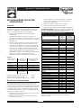
• Generator / Générateur
• Wheel kit / Ensemble de roulettes
• Locking 30 Amp plug / Prise de verrouillage 30 Ampères
• Engine oil / d'huile moteur
• Two packets of fuel stabilizer / Deux paquets de stabilisateur
d'essence
• Owner's manual / Manuel de l'utilisateur
• Engine manual / Manuel du moteur
*If any parts are missing or damaged, call 1-800-270-1408.
*Si certaines pièces sont manquantes ou endommagées, appelez le
1-800-270-1408.
Parts Included* / Pièces Incluses*
Table of Contents / Table des Matières

2
WheelHouse™ 5500 Watt Generator
EQUIPMENT
DESCRIPTION
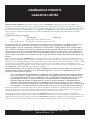
This generator is an engine–driven, revolving field,
alternating current (AC) generator. It was designed to
supply electrical power for operating compatible electrical
lighting, appliances, tools and motor loads.
This manual contains information for a generator that
operates 120 and/or 240 Volt, single phase, 60 Hz devices
that require up to 5,500 watts (5.5 kW) of power that pull
up to 45.8 Amps at 120 Volts or 22.9 Amps at 240 Volts.
CAUTION! Do Not exceed the generator’s
wattage/amperage capacity.Add up the rated watts of all
devices you are connecting to generator receptacles at one
time.This total should not be greater than 5,500 watts. See
“Don’t Overload the Generator” on page 9.
The generator’s revolving field is driven at about 3,600 rpm
by a single-cylinder engine.
Every effort has been made to ensure that information in
this manual is accurate and current. However, Generac
reserves the right to change, alter or otherwise improve the
product and this document at any time without prior
notice.
CAUTION! Do Not tamper with engine
governed speed. High operating speeds are
dangerous and increase risk of personal injury or
damage to equipment.The generator supplies
correct rated frequency and voltage only when
running at proper governed speed. Incorrect
frequency and/or voltage can damage some
connected electrical loads. Operating at excessively
low speeds imposes a heavy load.When adequate
engine power is not available engine life may be
shortened.
The Emission Control System for this generator is
warranted for standards set by the Environmental
Protection Agency. For warranty information refer to the
engine owner’s manual.
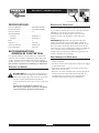
SAFETY RULES
This generator set was designed and manufactured for
specific applications. Do Not attempt to modify the unit or
use it for any application it was not designed for. If you have
any questions about your generator’s application, ask your
dealer or consult the factory.
The manufacturer could not possibly anticipate every
circumstance that might involve a hazard. For that reason
warnings in the manual and warnings on tags or decals
affixed to the unit are not all–inclusive. If you intend to
handle, operate or service the unit by a procedure or
method not specifically recommended by the manufacturer,
first make sure that such a procedure or method will not
render this equipment unsafe or pose a threat to you and
others.
Read this manual carefully and become familiar
with your generator set. Know its applications, its
limitations and any hazards involved.
WARNING! You must isolate the generator
from the electric utility using approved transfer
equipment if this unit is used for backup power.
Failure to isolate the generator from the
power utility may result in injury or death to
electric utility workers and damage to the
generator due to a backfeed of electrical energy.
Whenever the unit is providing backup power, the
electric utility must be notified.
DANGER! Generator exhaust gases contain
DEADLY carbon monoxide gas. If breathed in
sufficient concentrations, carbon monoxide
can cause unconsciousness or death. Operate
this equipment outdoors where adequate ventilation
is available.
The engine exhaust from this product contains
chemicals known to the State of California
to cause cancer, birth defects,
or other reproductive harm.
WARNING:
This is the safety alert symbol. It is used to alert you to potential personal injury hazards.
Obey all safety messages that follow this symbol to avoid possible injury or death.

WheelHouse™ 5500 Watt Generator
3
• The generator produces a very powerful voltage that can
cause serious injury or death by electrocution. Never
touch bare wires or receptacles. Never permit a child or
any unqualified person to operate the generator.
• Never handle any kind of electrical cord or device while
standing in water, while barefoot or while hands or feet
are wet. Death or serious injury from electrocution may
result.
• Use a ground fault circuit interrupter (GFCI) in any damp
or highly conductive area (such as metal decking or steel
work).
• Never use worn, bare, frayed or otherwise damaged
electrical cords with the generator. Death, serious injury
and property damage from electrical shock may result.
• Gasoline is highly FLAMMABLE and its vapors are
EXPLOSIVE. Never allow smoking, open flames,
sparks or heat in the vicinity while handling
gasoline. Avoid spilling gasoline on a hot engine. Comply
with all laws regulating storage and handling of gasoline.
• Do Not overfill the fuel tank.Always allow room for fuel
expansion. If tank is overfilled, fuel can overflow
onto a hot engine and cause a FIRE or an
EXPLOSION.
• Never store a generator with fuel in the tank where
gasoline vapors might reach an open flame, spark or pilot
light (as on a furnace, water heater, clothes dryer). FIRE
or an EXPLOSION may result.
• The unit requires an adequate flow of cooling air for its
continued proper operation. Never operate the unit
inside any room or enclosure where the free flow of
cooling air into and out of the unit might be obstructed.
Allow at least 2 feet of clearance on all sides of generator,
even while operating unit outdoors, or you could damage
the unit.
• Never start or stop the unit with electrical loads
connected to receptacles with the connected devices
turned ON. Start the engine and let it stabilize before
connecting any electrical loads. Disconnect all electrical
loads before shutting down the generator.
• Do Not insert any object through cooling slots of the
engine.You could damage the unit or injure yourself.
• Never operate the generator:
in rain; in any enclosed compartment; when connected
electrical devices overheat; if electrical output is lost; if
engine or generator sparks; if flame or smoke is observed
while unit is running; if unit vibrates excessively.
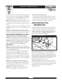
GROUNDING THE
GENERATOR
The National Electrical Code requires that the frame and
external electrically conductive parts of this generator be
properly connected to an approved earth ground. Local
electrical codes may also require proper grounding of the
unit. For that purpose, a GROUNDING WING NUT is
provided on the generator end (Figure 1).
Generally, connecting a No. 12 AWG (American Wire
Gauge) stranded copper wire to the grounding wing nut
and to an earth–driven copper or brass grounding rod
(electrode) provides adequate protection against electrical
shock. Be careful to keep the grounding wire attached after
connecting the stranded copper wire. However, local codes
may vary widely. Consult with a local electrician for
grounding requirements in your area.
Properly grounding the generator helps prevent electrical
shock if a ground fault condition exists in the generator or
in connected electrical devices. Proper grounding also helps
dissipate static electricity, which often builds up in
ungrounded devices.
Figure 1 — Grounding Wing Nut
Grounding
Wing Nut

4
WheelHouse™ 5500 Watt Generator
Your generator requires some assembly and is ready for
use after it has been properly serviced with the
recommended oil and fuel. If you have any problems with
the assembly of your generator, please call the generator
helpline at 1-800-270-1408.
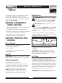
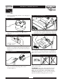
REMOVE GENERATOR
FROM CARTON
• Set the carton on a rigid flat surface with “This Side Up”
arrows pointing upward.
• Carefully open the top flaps of the shipping carton.
• Cut carton corners from top to bottom at end of carton
near wheels. Lay that side of carton down flat.
• Remove all packing material, carton fillers, etc.
• Roll the generator out of the shipping carton.
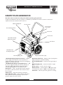
BEFORE STARTING THE
ENGINE
Secure Handle
Secure the handle using the following steps:
• Loosen knobs of the handle.
• Raise the handle.
• Insert handle pins, if equipped (P/N B4135).
• Hand tighten knobs.
Add Oil
CAUTION! Any attempt to crank or start the engine
before it has been properly filled with the recommended
oil may result in an engine failure.
To fill your engine with oil:
• Place generator on a level surface.
• Use a long neck funnel OR remove the fuel tank as
described in “Fuel Tank”, when adding or changing oil.
• Follow the oil grade recommendations and oil fill
instructions given in the engine owner’s manual.
NOTE: The generator’s revolving field rides on a
prelubricated and sealed ball bearing that requires no
additional lubrication for the life of the bearing.
Add Gasoline
WARNING! Never fill fuel tank indoors. Never
fill fuel tank when engine is running or hot.Allow unit
to cool for two minutes before refueling. Do Not
light a cigarette or smoke when filling the fuel tank.
WARNING! Do Not overfill the fuel tank. See
decal on tank.
• Use fresh, clean regular UNLEADED gasoline. Do Not
use premium gasoline. Do Not mix oil with gasoline.
Never use engine or carburetor cleaner products in the
fuel tank.
• Clean area around fuel fill and remove fuel cap/gauge.
• Slowly add gasoline to fuel tank.Allow about 1.5" of tank
space for fuel expansion (Figure 2).
• Install fuel cap and permit any spilled gasoline to
evaporate.
IMPORTANT: It is important to prevent gum deposits
from forming in essential fuel system parts, such as the
carburetor, fuel filter, fuel hose or tank during storage. Be
sure to review “Storage” on page 11.
Fuel Tank
As is common with all plastic fuel containers, the
removable fuel tank supplied with this generator may swell
or expand due to build-up of fuel vapors when the vent
knob is closed.This tank is designed and has been tested to
safely withstand pressure-buildup.The 'ballooning' condition
is relieved by turning the vent knob fully counterclockwise
or loosening and retightening the fuel cap/gauge.When
installing the tank on your generator, relieve tank pressure
before tightening the four large plastic wing nuts.
IMPORTANT: The vent knob should be closed whenever
you move the generator or transport the fuel tank.
Figure 2 — Typical Fuel Expansion Space
Fuel
Tank
1.5” Air Space

WheelHouse™ 5500 Watt Generator
5
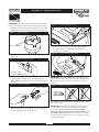
1. Turn the vent knob fully clockwise on the fuel gauge to
close it (Figure 3).
2. Turn the fuel shut off valve to the “Off” position
(Figure 4).
3. Disconnect the quick connect on the fuel line by
pushing on the metal tab and twisting apart (Figure 5).
Release the metal tab. Some fuel that is left in the line
will spill out.
4. Remove the four large plastic wing nuts holding the
tank onto the frame by turning them counter-
clockwise (Figure 6).
5. Lift off the fuel tank by grasping the handle (provided
on the tank) with one hand and putting the other hand
in the finger pocket (Figure 7). Lift the tank straight up.
IMPORTANT: The fuel tank MUST be filled with it lying
flat, not slanted or standing upright (Figure 8). Do Not let
the fuel valve and quick connect come in contact with any
dirt.
To place the fuel tank back on the unit, follow these same
steps in reverse order.
IMPORTANT: Remove any dirt found inside the quick
connect before putting the fuel tank back on the unit.
Make sure the vent knob is turned fully counter-
clockwise to open it. If you don’t open it, fuel will not
flow into the fuel line causing the unit to not start.
Figure 3 — Vent Knob
Vent Knob
Figure 4 — Fuel Shut-off Valve
Fuel Valve is shown in
the “Off” position
Figure 5 — Quick Connect
Figure 6 — Plastic Tank Wing Nuts
Figure 7 — Lifting Off Fuel Tank
Figure 8 — Fuel Tank
Fuel Tank

6
WheelHouse™ 5500 Watt Generator
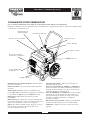
KNOW YOUR GENERATOR
Read this owner’s manual and safety rules before operating your generator.
Compare the illustrations with your generator, to familiarize yourself with the locations of various controls and
adjustments. Save this manual for future reference.
120 Volt AC, 20 Amp
Duplex Receptacle
Removable Fuel Tank
Choke Lever
Recoil Starter
(not shown)
Rocker Switch
Circuit Breakers (AC)
120/240 Volt AC,
30 Amp Receptacle
Air Cleaner
Grounding Wing Nut
Oil Fill Cap/Dipstick
120 Volt AC, 20 Amp, Duplex Receptacle — May be
used to supply electrical power for the operation of
120 Volt AC, 20 Amp, single phase, 60 Hz electrical lighting,
appliance, tool and motor loads.
120/240 Volt AC, 30 Amp Locking Receptacle — May
be used to supply electrical power for the operation of
120 and/or 240 Volt AC, 30 Amp, single phase, 60 Hz
electrical lighting, appliance, tool and motor loads.
Air Cleaner — Uses a dry type filter element and foam
pre–cleaner to limit the amount of dirt and dust sucked
into the engine.
Choke Lever — Used when starting a cold engine.
Circuit Breakers (AC) — Each receptacle is provided
with a "push to reset" circuit breaker to protect the
generator against electrical overload.
Removable Fuel Tank — Capacity of five (5) U.S. gallons.
Easily removed for convenient refueling.
Grounding Wing Nut — Used for proper grounding of
unit.
Oil Fill Cap/Dipstick — Check and add oil to engine
here.
Recoil starter — Used to start the engine.
Rocker Switch — Set this switch to "On" before using
recoil starter. Set switch to "Off" to switch OFF engine.
Vent Knob — Must be open when generator is running.
Vent Knob

WheelHouse™ 5500 Watt Generator
7
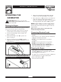
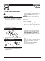
OPERATING THE
GENERATOR
CAUTION! Never start or stop unit with
electrical loads connected AND with the connected
devices turned ON.
Starting the Engine
Disconnect all electrical loads from the generator. Follow
these start instruction steps in numerical order:
1. Make sure the fuel line quick connect is hooked up
and that all four tank hold-downs are firmly tight.
2. Turn the vent knob fully counter-clockwise. See
Figure 3 on page 5.
3. Rotate the fuel valve to the “On” position. See
Figure 4 on page 5.
4. Move the choke lever to the “Choke” position
(Figure 9).Your unit may appear slightly different from
that shown here.
5. Set the rocker switch to “On” position (Figure 10).
6. Grasp the recoil handle and pull slowly until slight
resistance is felt.Then pull rapidly to start engine.
7. Move choke lever to “Run” position a short distance at
a time over several seconds in warm weather or
minutes in cold weather. Let engine run smoothly before
each change. Operate with choke in “Run” position.
NOTE: If engine still fails to start after 3 pulls, check for
proper oil level in crankcase.This unit is equipped with a
low oil device that will not allow the engine to start. See
engine manual.
Refer to the engine owner’s manual for more
detailed starting instructions.
Connecting Electrical Loads
• Let engine stabilize and warm up for a few minutes after
starting.
• Plug in and turn on the desired 120 and/or 240 Volt AC,
single phase, 60 Hz electrical loads.
• Do Not connect 240 Volt loads to the 120 Volt
receptacles.
• Do Not connect 3–phase loads to the generator.
• Do Not connect 50 Hz loads to the generator.
• DO NOT OVERLOAD THE GENERATOR. See
“Don’t Overload the Generator” on page 9.
Stopping the Engine
• Unplug all electrical loads from generator panel
receptacles. Never start or stop engine with electrical
devices plugged in and turned on.
• Let engine run at no–load for 30 seconds to stabilize the
internal temperatures of engine and alternator.
• Move rocker switch to “Off”.
• Close the fuel shut–off valve.
Figure 9 — Choke Lever
Figure 10 — Rocker Switch

8
WheelHouse™ 5500 Watt Generator
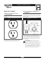
RECEPTACLES
The control panel is equipped with a flip-up panel to keep
the outlets clean and protected.
120 Volt AC, 20 Amp, Duplex
Receptacle
Each receptacle (Figure 11) is protected against overload
by a push–to–reset circuit breaker.
Use each receptacle to operate 120 Volt AC, single–phase,
60 Hz electrical loads requiring up to 2,400 watts (2.4 kW)
at 20 Amps of current. Use cord sets that are rated for
125 Volt AC loads at 20 Amps (or greater).
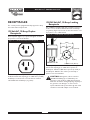
120/240 Volt AC, 30 Amp, Locking
Receptacle
Use a NEMA L14–30 plug with this receptacle. Connect a
4–wire cord set rated for 250 Volt AC loads at 30 Amps
(or greater) (Figure 12).You can use the same 4–wire cord
if you plan to run a 120 Volt load.
This receptacle powers 120/240 Volt AC, 60 Hz, single
phase loads requiring up to 3,600 watts of power at
30 Amps for 120 Volts; 5,500 watts of power (5.5 kW) at
22.9 Amps for 240 Volts.The outlet is protected by a
push–to–reset circuit breaker.
CAUTION! Although this outlet is rated for
120/240 Volt 30 Amp (up to 7,200 watts), the
generator is only rated for 5,500 watts. Powering
loads that exceed the wattage/amperage capacity of
the generator can damage it or cause serious
injuries. 240 Volt loads powered through this outlet
should not exceed 22.9 Amps of current draw.
Figure 11 — 120 Volt AC, 20 Amp Duplex Receptacle
Figure 12 — 120/240 Volt AC, 30 Amp Receptacle
4-Wire Cord Set
240V
120V
120V
W (Neutral)
X (Hot)
Y (Hot)
NEMA L14-30
Ground (Green)

WheelHouse™ 5500 Watt Generator
9
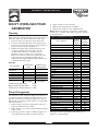
DON'T OVERLOAD YOUR
GENERATOR
Capacity
You must make sure your generator can supply enough
rated (running) and surge (starting) watts for the items you
will power at the same time. Follow these simple steps:
1. Select the items you will power at the same time.
2. Total the rated (running) watts of these items.This is
the amount of power your generator must produce to
keep your items running. See Figure 13.
3. Estimate how many surge (starting) watts you will
need. Surge wattage is the short burst of power
needed to start electric motor-driven tools or
appliances such as a circular saw or refrigerator.
Because not all motors start at the same time, total
surge watts can be estimated by adding only the
item(s) with the highest additional surge watts to the
total rated watts from step 2.
Example:
Total Rated (Running) Watts = 3075
Highest Additional Surge Watts = 1800
Total Generator Output Required = 4875
Power Management
To prolong the life of your generator and attached devices,
it is important to take care when adding electrical loads to
your generator.There should be nothing connected to the
generator outlets before starting it's engine.The correct
and safe way to manage generator power is to sequentially
add loads as follows:
1. With nothing connected to the generator, start the
engine as described in this manual.
2. Plug in and turn on the first load, preferably the largest
load you have.
3. Permit the generator output to stabilize (engine runs
smoothly and attached device operates properly.
4. Plug in and turn on the next load.
5. Again, permit the generator to stabilize.
6. Repeat steps 4 and 5 for each additional load.
Never add more loads than the generator capacity.Take
special care to consider surge loads in generator capacity,
as described above.
*Wattages listed are approximate only. Check tool or
appliance for actual wattage.
Tool or Appliance
Rated (Running)
Watts
Additional Surge
(Starting) Watts
Window Air
Conditioner
1200 1800
Refrigerator 800 1600
Deep Freezer 500 500
Television 500 -
Light (75 Watts) 75 -
3075 Total
Running Watts
1800 Highest
Surge Watts
Tool or Appliance
Rated*
(Running)
Watts
Additional
Surge
(Starting)
Watts
Essentials
Light Bulb - 75 watt 75 -
Deep Freezer 500 500
Sump Pump 800 1200
Refrigerator/Freezer - 18 Cu. Ft. 800 1600
Water Well Pump - 1/3 HP 1000 2000
Heating/Cooling
Window AC - 10,000 BTU 1200 1800
Window Fan 300 600
Furnace Fan Blower - 1/2 HP 800 1300
Kitchen
Microwave Oven - 1000 Watt 1000 -
Coffee Maker 1500 -
Electric Stove - Single Element 1500 -
Hot Plate 2500 -
Family Room
DVD/CD Player 100 -
VCR 100 -
Stereo Receiver 450 -
Color Television - 27” 500 -
Personal Computer w/17” monitor 800 -
Other
Security System 180 -
AM/FM Clock Radio 300 -
Garage Door Opener - 1/2 HP 480 520
Electric Water Heater - 40 Gallon 4000 -
DIY/Job Site
Quartz Halogen Work Light 1000
Airless Sprayer - 1/3 HP 600 1200
Reciprocating Saw 960 960
Electric Drill - 1/2 HP 1000 1000
Circular Saw - 7 1/4” 1500 1500
Miter Saw - 10” 1800 1800
Table Planer - 6” 1800 1800
Table Saw/Radial Arm Saw - 10” 2000 2000
Air Compressor - 1-1/2 HP 2500 2500
Figure 13 - Wattage Reference Chart

10
WheelHouse™ 5500 Watt Generator
SPECIFICATIONS
Maximum Surge Watts . . . . . . . . . . . . . . . . .8,500 watts
Continuous Wattage Capacity . . . . . . . . . . .5,500 watts
Power Factor . . . . . . . . . . . . . . . . . . . . . . . . . . . . . .1.0
Rated Maximum Continuous AC Load Current:
At 120 Volts . . . . . . . . . . . . . . . . . . . . . . .45.8 Amps
At 240 Volts . . . . . . . . . . . . . . . . . . . . . . .22.9 Amps
Phase . . . . . . . . . . . . . . . . . . . . . . . . . . . . . . . . .1–phase
Rated Frequency . . . . . . . . . . . . . . . . . . . . . . .60 Hertz
Fuel Tank Capacity. . . . . . . . . . . . . . . . . . . 5 U.S. gallons
Shipping Weight . . . . . . . . . . . . . . . . . . . . . . . . . 153 lbs.
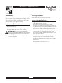
GENERAL MAINTENANCE
RECOMMENDATIONS
The Owner/Operator is responsible for making sure that
all periodic maintenance tasks are completed on a timely
basis; that all discrepancies are corrected; and that the unit
is kept clean and properly stored. Never operate a
damaged or defective generator.
Engine Maintenance
See engine owner’s manual for instructions.
CAUTION! Avoid prolonged or repeated skin
contact with used motor oil. Used motor oil has
been shown to cause skin cancer in certain
laboratory animals.Thoroughly wash exposed areas
with soap and water.
KEEP OUT OF REACH OF CHILDREN. DON'T
POLLUTE. CONSERVE RESOURCES. RETURN
USED OIL TO COLLECTION CENTERS.
Generator Maintenance
Generator maintenance consists of keeping the unit clean
and dry. Operate and store the unit in a clean dry
environment where it will not be exposed to excessive
dust, dirt, moisture or any corrosive vapors. Cooling air
slots in the generator must not become clogged with
snow, leaves or any other foreign material.
NOTE: Do Not use a garden hose to clean generator.
Water can enter engine fuel system and cause problems. In
addition, if water enters generator through cooling air
slots, some of the water will be retained in voids and
cracks of the rotor and stator winding insulation.Water
and dirt buildup on the generator internal windings will
eventually decrease the insulation resistance of these
windings.
To Clean the Generator
• Use a damp cloth to wipe exterior surfaces clean.
• A soft bristle brush may be used to loosen caked on dirt
or oil.
• A vacuum cleaner may be used to pick up loose dirt and
debris.
• Low pressure air (not to exceed 25 psi) may be used to
blow away dirt. Inspect cooling air slots and opening on
generator.These openings must be kept clean and
unobstructed.

WheelHouse™ 5500 Watt Generator
11
STORAGE
The generator should be started at least once every seven
days and allowed to run at least 30 minutes. If this cannot
be done and you must store the unit for more than
30 days, use the following guidelines to prepare it for
storage.
Generator Storage
• Clean the generator as outlined in “To Clean the
Generator.”
• Check that cooling air slots and openings on generator
are open and unobstructed.
CAUTION! Storage covers can be flammable.
Do Not place a storage cover over a hot
generator. Let the unit cool for a sufficient time
before placing the cover on the unit.
Engine Storage
See engine owner’s manual for instructions.
Other Storage Tips
• Always store unit with fuel shut off valve in the “Off”
position (Figure 4, earlier).
• To prevent gum from forming in fuel system or on
essential carburetor parts, empty entire contents of both
supplied fuel stabilizer containers into fuel tank and fill
with fresh gasoline. Run the unit for several minutes to
circulate the additive through the carburetor.The unit
and fuel can then be stored for up to 24 months.
Additional fuel stabilizer can be purchased locally.
• Fuel tank may swell in storage if vent is closed.When
storing generator with fuel in the tank, make sure the
vent knob is turned fully counter-clockwise.
• Store unit in clean and dry area.

12
WheelHouse™ 5500 Watt Generator
NOTES

WheelHouse™ 5500 Watt Generator
13
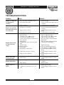
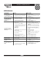
TROUBLESHOOTING
Problem Cause Solution
Engine is running, but
no AC output is
available.
1.
Circuit breaker is open.
2.
Poor connection or defective cord set.
3.
Connected device is bad.
4.
Fault in generator.
1.
Reset circuit breaker.
2.
Check and repair.
3.
Connect another device that is in good
condition.
4.
Contact Generac service facility.
Engine runs good but
bogs down when loads
are connected.
1.
Short circuit in a connected load.
2.
Generator is overloaded.
3.
Engine speed is too slow.
4.
Shorted generator circuit.
1.
Disconnect shorted electrical load.
2.
See “Don’t Overload the Generator”
on page 9.
3.
Contact Briggs and Stratton service
facility.
4.
Contact Generac service facility.
Engine will not start;
or starts and runs
rough.
1.
Rocker switch set to “Stop”.
2.
Dirty air cleaner.
3.
Fuel valve is in the “Off” position.
4.
Vent knob in fuel gauge is closed.
5.
Quick connect in fuel line is disconnected.
6.
Out of gasoline.
7.
Stale gasoline.
8.
Spark plug wire not connected to spark
plug.
9.
Bad spark plug.
10.
Water in gasoline.
11.
Overchoking.
12.
Excessively rich fuel mixture.
13.
Intake valve stuck open or closed.
14.
Engine has lost compression.
1.
Set switch to “Run”.
2.
Clean or replace air cleaner.
3.
Turn fuel valve to the “On” position.
4.
Open vent knob in fuel gauge.
5.
Reconnect quick connect in fuel line.
6.
Fill fuel tank.
7.
Drain gas tank and fill with fresh fuel.
8.
Connect wire to spark plug.
9.
Replace spark plug.
10.
Drain gas tank; fill with fresh fuel.
11.
Put choke lever to “Run” position.
12.
Contact Briggs and Stratton service
facility.
13.
Contact Briggs and Stratton service
facility.
14.
Contact Briggs and Stratton service
facility.
Engine shuts down
during operation.
1.
Out of gasoline.
2.
Fault in engine.
1.
Fill fuel tank.
2.
Contact Briggs and Stratton service
facility.
Engine lacks power.
1.
Load is too high.
2.
Dirty air filter.
1.
See “Don’t Overload the Generator”
on page 9.
2.
Replace air filter.
Engine “hunts” or
falters.
1.
Choke is opened too soon.
2.
Carburetor is running too rich or too
lean.
1.
Move choke to halfway position till
engine runs smoothly.
2.
Contact Briggs and Stratton service
facility.

14
WheelHouse™ 5500 Watt Generator
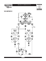
SCHEMATIC

WheelHouse™ 5500 Watt Generator
15
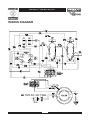
WIRING DIAGRAM

16
WheelHouse™ 5500 Watt Generator
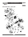
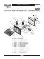
EXPLODED VIEW – MAIN UNIT

WheelHouse™ 5500 Watt Generator
17
PARTS LIST – MAIN UNIT
Item Part # Qty Description
1 A189457GS 1 FRAME
2 70642GS 2 MOUNT,Vibration 45°
3 84346GS 2 PPHMS, M8 - 1.25 x 35
4 66365GGS 1 HOUSING, Engine Adapter
5 187746GS 1 ASSEMBLY, Rotor (Inclds Item 7)
6 187745GS 1 ASSEMBLY, Stator
7 65791GS 1 BEARING
8 96796GS 1 WASHER, M8 Flat
9 189920GS 1 DECAL, Cover Air Cleaner
10 86307GS 4 SCREW, 5/16-24 x 3/4 SEMS
11 99383GS 1 SCREW, 5/16-24 x 7-3/8
12 76222GS 1 PPHMS, M8 - 1.25 x 40
13 189127GS 1 GROMMET, Rubber
14 189009GS 1 BRACKET, Muffler
15 188551GS 1 GASKET, Exhaust
16 66476GS 2 SCREW, M6-1 x 12 w/Lock
Washer
17 189008GS 1 MUFFLER
18 60706GS 2 SCREW, 5/16 - 18 x 3/4"
19 83083GS 1 SCREEN, Spark Arrest
20 81917GS 1 PIN, 4mm x 10 Roll
21 67989GS 9 NUT, Flange Serrated
22 85652GS 2 MOUNT,Vibration
23 67022GS 1 GROMMET, Rubber
24 J189011AGS 1 SHIELD, Heat
25 SRV66825DGS 1 CARRIER, Rear Bearing
26 74908GS 5 TAPTITE, M5-0.8 x 10
27 86308AGS 4 BOLT, M6-1 x 145mm Stator
28 84409GS 1 SLEEVING, Flexo, HW 1/2" X 15"
29 22695GS 1 FASTEN, On Tab Housing 6P
30 84242GS 1 GROMMET, Plastic
31 188333GS 1 DECAL, Fuel Tank
32 91825GS 1 ASSEMBLY, Brush Holder
33 66849GS 2 TAPTITE, M5-0.8 x 16
34 B4871GS 1 COVER, Bearing Carrier
35 23762GS 2 WASHER, #10 Ext. Shakeproof
36 86494GS 1 SCREW, M6-1.0 x 16 Wing
37 B2153GS 5 SCREW, #10 Self Drilling
38 188194GS 2 BLIND RIVET
39 71693GS 2 WASHER, Flat
40 27007GS 2 MOUNT, Rubber Foot
41 80270GS 1 VALVE,Tank
42 78299GS 1 BUSHING, Plastic Tank
Item Part # Qty Description
43 189420GS 1 CAP, Fuel Gauge
44 189397GS 1 TANK, Fuel, 5 Gallon (Includes
Items 41 & 42)
45 94480GS 1 DECAL, Start Instructions
46 22097GS 4 WASHER, Lock
47 22127GS 4 NUT, 1/4-20
48 14353621GS 1 WIRE, Ground
49 26850GS 2 WASHER, M6 Shakeproof
50 B4986GS 1 DECAL, Ground, Green
51 94479GS 1 DECAL, Danger
52 189098GS 2 WHEEL, 14 x 1.75, 1/2" Hub
53 75402GS 2 PUSHNUT, 1/2"
54 BB3061GS 1 BOTTLE, Oil, 28 oz
55 187330GS 1 HOOD, Rocker Arm Cover
56 A188205GS 1 HANDLE
57 189456GS 1 KIT, Handle Fastening
58 189157GS 1 ASSEMBLY, Control Panel
59 189164GS 4 NUT, Palnut 3/16"
60 189117GS 1 QUICK CONNECT, Fuel, 1/4
Barb
61 189115GS 1 QUICK CONNECT, Fuel, 1/4
Barb
62 189919GS 1 DECAL, Logo
63 189114GS 4 KNOB, Fuel Tank Hold Down
64 77816GS 2 DECAL, Hot Muffler
65 189332GS 2 CAP PLUG, 1 - 1/4" O.D.
66 73054GS 1 DECAL, Shut-Off, Fuel
67 20566GS 1 DECAL, 1-800 #
68 189867AGS 1 HOSE, 1/4" x 51mm
69 48031CGS 4 CLAMP
70 189922GS 1 MANUAL, Owners
71 188637GS 1 MANUAL, Engine
72 43438GS 1 PLUG, 250V, 30A
73 189208GS 2 STABILIZER, 1oz Tube
74 189867BGS 1 HOSE, 1/4" x 159mm
75 49808GS 2 WASHER, M12 Flat
76 189521AGS 1 WIRE, Ground Panel
77 B4135GS 2 PIN, with Lanyard
78 189332AGS 2 CAP PLUG, 1-1/4" O.D.
79 74728GS 1 DECAL, Neutral Ground
80 94479GS 1 DECAL, Neutral Ground, French
900 NSP 1 ENGINE

18
WheelHouse™ 5500 Watt Generator
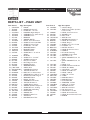
EXPLODED VIEW AND PARTS LIST – CONTROL PANEL
Item Part # Qty Description
1 188914GS 1 COVER, Lid, Control Panel
2 188889GS 1 CONTROL PANEL, Compact
3 189167GS 2 CLIP, Hinge Pin Retainer
4 189182GS 2 SPRING, Hinge, Pin
5 189166GS 2 PIN, Hinge, Cover, Compact
6 68759GS 2 OUTLET, 120V, 20Amp, Duplex
7 189165GS 4 NUT, Palnut, Pushnut, 5/32
8 84198GS 2 CAP, Circuit Breaker
9 75207GS 2 CIRCUIT BREAKER
10 43437GS 1 OUTLET, 120/240 Locking, 30A
11 189164GS 2 NUT, Palnut, Pushnut, 3/16
12 84543CGS 2 SCREW, Phillips, Head 3.5 x 18
13 93857GS 1 BAR, Retaining
14 188890GS 1 COVER, Back, Control Panel
15 82308GS 6 SCREW, Self Tapping, STC 3x
16 22694GS 1 HOUSING, Receptacle

WheelHouse™ 5500 Watt Generator
19
NOTES

WheelHouse™ 5500 Watt Générateur
20
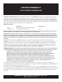
DESCRIPTION DE L ÉQUIPEMENT
Ce générateur est un générateur entraîné par un moteur à champ
magnétique rotatif produisant du courant alternatif (c.a.). Il a été
conçu pour fournir du courant électrique pour faire marcher des
charges compatibles d'éclairage, d'appareils ménagers, d'outil et de
moteur.
Ce manuel contient des informations sur un générateur qui fait
marcher des appareils de 120 et/ou 240 Volts, monophasés,
60 Hertz nécessitant jusqu'à 5,500 watts (5,5 kW) de puissance
qui tirent jusqu'à 45,8 Ampères à 120 Volts ou 22,9 Ampères à
240 Volts.
ATTENTION! Ne Pas dépasser la capacité en watts ou en
ampères du générateur.Ajoutez les watts de tous les appareils que
vous branchez aux prises du générateur en même temps. Ce total
ne doit pas être supérieur à 5,500 watts pour ce générateur.Voir
"Ne Pas Surcharger le Générateur" sur la page 27 pour
l'information spécifique.
Le champ tournant du générateur est entraîné à 3600 T/M par un
moteur monocylindrique.
Tout a été mis en oeuvre pour que les informations contenues
dans ce manuel soient exactes et à jour. Cependant, Generac se
réserve le droit de changer, d'altérer ou d'améliorer le produit à
n'importe quel moment sans avis préalable.
ATTENTION! Ne Pas toucher à la vitesse préréglée
du moteur. Des vitesses élevées d'opération sont
dangereuses et augmentent le risque de blessures
personnelles ou d'endommagement de l'équipement. Le
générateur ne fournit une fréquence et un voltage
corrects que lorsque le moteur tourne à la vitesse
préréglée correcte. Une fréquence et/ou un voltage
incorrect peut endommager certaines charges électriques
branchées. Le fait de faire marcher l'appareil à des vitesses
plus lentes que celle qui est prévue impose une lourde
charge au moteur, lorsque la puissance adéquate du
moteur n'est pas disponible et cela peut raccourcir la
durée de vie du moteur.
Le Système de contrôle de l'émission du générateur est garanti
pour des normes établies par L'Agence de protection de
l'environnement. Pour des informations sur la garantie, se reporter
au manuel du moteur.
RÈGLES DE SÉCURITÉ
Ce générateur a été conçu et fabriqué pour des applications
particulières. Ne Pas essayer de modifier l'appareil ni de l'utiliser
pour une application pour laquelle il n'a pas été conçu. Si vous
avez des questions au sujet de l'application de votre générateur,
posez-les à votre Concessionnaire/ Distributeur ou consultez
l'usine.
Le fabricant n'a pas pu prévoir toutes les circonstances qui
peuvent provoquer un danger. Pour cette raison les
avertissements qui se trouvent dans le manuel et ceux qui sont
collés sur la machine ne sont pas exhaustifs. Si vous avez
l'intention de manipuler, de faire marcher ou de réparer cet
appareil selon des procédures ou des méthodes qui ne sont pas
spécialement recommandées par le fabricant, il faut vous assurer
d'abord que ces procédures et ces méthodes ne risquent pas de
rendre l'appareil dangereux ou posent un danger à vous ou aux
autres.
Lisez avec soin ce manuel et familiarisez-vous avec votre
générateur. Connaissez ses applications, ses limitations et
les dangers qu'il implique.
AVERTISSEMENT! Vous devez isoler le générateur
de l'installation électrique avec un équipement de transfert
homologué, au cas où vous utiliseriez cette unité pour une
alimentation de secours. Le manquement à isoler le
générateur de l'installation électrique, risque de
provoquer des blessures ou même d'être fatal pour
les ouvriers et de causer des dommages au
générateur dus à un backfeed d'énergie électrique. Les
services publics d'électricité doivent être avisés si l'unité
produit de l'énergie de secours.
DANGER! Le générateur épuise des gaz
contiennent le gaz de monoxide de carbone
MORTEL. Si a aspiré suffisant concentrations,
carbone peut causer unconsciousness ou mort.
Ceci opérer l'équipement extérieur où ventilation suffisant
est disponible.
L’échappement du moteur de ce produit contient des produits
chimiques que l’État de Californie considère comme causant le
cancer, des déformations à la naissance ou d’autres dangers
concernant la reproduction.
AVERTISSEMENT
Ceci est la sûreté le symbole vif. Il est utilisé à l'alerte vous aux dangers de blessure personnels potentiels.
Obéir tous messages de sûreté qui suivent ce symbole à évite la blessure ou la mort possibles.
La page charge ...
La page charge ...
La page charge ...
La page charge ...
La page charge ...
La page charge ...
La page charge ...
La page charge ...
La page charge ...
La page charge ...
La page charge ...
La page charge ...
-
 1
1
-
 2
2
-
 3
3
-
 4
4
-
 5
5
-
 6
6
-
 7
7
-
 8
8
-
 9
9
-
 10
10
-
 11
11
-
 12
12
-
 13
13
-
 14
14
-
 15
15
-
 16
16
-
 17
17
-
 18
18
-
 19
19
-
 20
20
-
 21
21
-
 22
22
-
 23
23
-
 24
24
-
 25
25
-
 26
26
-
 27
27
-
 28
28
-
 29
29
-
 30
30
-
 31
31
-
 32
32


Simplicity 01655-0 Manuel utilisateur
- Catégorie
- Groupes électrogènes
- Taper
- Manuel utilisateur
dans d''autres langues
- English: Simplicity 01655-0 User manual