La page est en cours de chargement...

- Do not store or use gasoline or other flammable
vapors and liquids in the vicinity of this or any
other appliance.
- WHAT TO DO IF YOU SMELL GAS
• Do not try to light any appliance.
• Do not touch any electrical switch; do not use
any phone in your building.
• Leave the building immediately.
• Immediately call your gas supplier from a neigh-
bor’s phone. Follow the gas supplier’s instruc-
tions.
• If you cannot reach your gas supplier, call the
fire department.
- Installation and service must be performed by
a qualified installer, service agency or the gas
supplier.
WARNING:
FIRE OR EXPLOSION HAZARD
Failure to follow safety warnings exactly could
result in serious injury, death, or property damage.
AVERTISSEMENT:
RISQUED’INDENDIE OU D’EXPLOSION
Le non-respect Des avertissements de sécurité
pourrait d’entraîner des blessures graves, la mort
ou des dommages matériels.
- Ne pas entreposer ni utilizer d’essence ni d’autres
vapeurs ou liquides inflammables dans le voisinage
de cet appareil ou de tout autre appareil.
- QUE FAIRE SI VOUS SENTEZ UNE ODEUR DE GAZ:
• Ne pas tenter d’allumer d’appareil.
• Ne touchez à aucan interrupteur. Ne pas vous servir
des téléphones se trouvant dans le bâtiment où
vous trouvez.
• Sortez immédiatement de bâtiment.
• Appelez immédiatement votre fournisseur de
gaz depuis un voisin. Suivez les instructions du
fournisseur.
• Si vous ne pouvez rejoindre le fournisseur de gaz,
appelez le service des incindies.
- L’installation et l’entretien doivent être assurés par
un installateur ou un service d’entretien qualifié
ou par le fournisseur de gaz.
INSTALLER: Leave this manual with the appliance.
CONSUMER: Retain this manual for future
reference.
Installateur : Laissez cette notice avec l’appareil.
Consommateur : Conservez cette notice pour
consultation ultérieure.
Decorative Product: Not for use as a heating
appliance.
NOTICE: Fireplace is not to be operated by a
thermostat.
Installation and Operation Instructions
Models
PFS
®
USC
Report No. F14-172
Ce manuel est disponible en francais, simplement
en faire la demande. Numéro de la pièce 900301-02.
P/N 900301-00 REV. F 08/2018
BRT40ST B-Vent Gas Fireplaces
BRT40STTMN
P900301-00

2
General Information
900301-00 08/2018
Innovative Hearth Products
BRT40ST See-Through B-Vent Gas Fireplaces
DANGER
HOT GLASS WILL
CAUSE BURNS.
DO NOT TOUCH GLASS
UNTIL COOLED.
NEVER ALLOW CHILDREN
TO TOUCH GLASS.
A barrier designed to reduce the risk of burns from the hot viewing glass is pro-
vided with this appliance and shall be installed for the protection of children and
other at-risk individuals.
DANGER
PELIGRO
VITRE CHAUDE
RISQUE DE BRÛLURES.
NE TOUCHEZ PAS UNE VITRE
NON REFROIDIE.
NE LAISSEZ JAMAIS UN ENFANT
DE TOUCHER LA VITRE.
EL VIDRIO CALIENTE
CAUSARÁ QUEMADURAS.
USTED DEBE NUNCA
TOCAR EL VIDRIO CALIENTE.
LOS NIÑOS DEBEN NUNCA
TOCAR EL VIDRIO.
L’écran pare-étincelles fourni avec ce foyer réduit le risque de brûlure en cas de
contact accidentel avec la vitre chaude et doit être installé pour la protection Des
enfants et Des personnes à risques.
Una barrera diseñada para reducir el riesgo de quemaduras desde la mirilla (vidrio)
caliente es proveida con este aparato y deberá instalarse para la protección de los
niños y otros individuos en riesgo.
Vea el volante adjunto para la representación de color adecuado
See attached color flyer for proper color representation
Voir ci-joint tract pour une bonne représentation de la couleur
SAFETY AND YOUR FIREPLACE

3
Afin d’éviter les brûlures
graves ou les blessures,
ne pas retirer l’écran de
protection de la foyer qui
empêche tout contact
direct avec la vitre.
Suivez les instructions de sécurité
ci-dessous et veillez à ce que tous
les membres de votre famille soient
conscients du danger de brûlure
encouru :
• Les surfaces de votre foyer deviennent
EXTRÊMEMENT CHAUDES !
• La vitre située à l'avant du foyer atteint
des températures EXTRÊMEMENT
ÉLEVÉES et peut causer de graves
blessures en cas de contact.
• Tenez les enfants à l'écart du foyer
lorsqu'il fonctionne. Surveillez
attentivement les enfants dans les
pièces où un foyer est utilisé afin
d'éviter qu'ils ne soient en contact avec
la vitre.
• Tenez tous les vêtements, les meubles,
l'essence et tout autre liquide
inflammable à l'écart du foyer.
• Même après fermeture du gaz, les
surfaces du foyer restent extrêmement
chaudes.
Veillez à coller les Étiquettes de mise
en garde relatives à la sécurité
d'utilisation à l'endroit où vous
utilisez le foyer, pour rappeler à tous
les utilisateurs les dangers liés aux
températures élevées
(Page 24)
.
Lisez L’information de sûreté
importante (Page 28)
.
Para evitar quemaduras y lesiones
graves, no quite el protector de malla
o guardia de seguridad que evita el
contacto directo con el vidrio.
Siga las instrucciones de seguridad
a continuación y asegúrese de que
todos en su hogar sepan acerca de este
peligro de quemadura:
• ¡Las superficies de la chimenea se
ponen MUY CALIENTES!
• El vidrio delante de la
chimenea alcanza temperaturas
EXTREMADAMENTE ALTAS y puede
causar quemaduras graves si se toca.
• Mantenga a los niños alejados de
la chimenea en funcionamiento.
Supervise en forma cercana a los niños
en cualquier cuarto donde haya una
chimenea funcionando para impedir el
contacto con el vidrio.
• Mantenga la ropa, mobiliario, gasolina
y otros líquidos inflamables alejados
de la chimenea.
• Aún después de haber apagado el
gas, las superficies de la chimenea
permanecen extremadamente
calientes.
Asegúrese de colocar las Etiquetas de
advertencia de seguridad de operación
en el lugar donde enciende la chimenea,
para que todos recuerden los peligros
asociados con las altas temperaturas
(Página 28)
.
Lea Información importante de
seguridad (Página 28).
Seguridad y su
chimenea
La sécurité et
votre foyer
[FRENCH][ENGLISH]
[SPANISH]
Safety and Your
Fireplace
To prevent severe burns
and injuries, do Not
remove the barrier on the
appliance which prevents
direct contact with the
glass.
Follow the safety instructions below
and be sure everyone in your household
understands this burn hazard:
• The surfaces on your fireplace get
EXTREMELY HOT!
• The glass on the front of the
fireplace reaches EXTREMELY HIGH
temperatures and can cause severe
burns if touched.
• Keep children away from an operating
fireplace. Closely supervise children
in any room where a fireplace is
operating to prevent contact with glass.
• Keep clothing, furniture, gasoline, and
other flammable liquids away from the
fireplace.
• Even after the gas is turned off,
fireplace surfaces remain extremely
hot.
Be sure to attach the enclosed Safety-
in-Operation Warnings where you
turn on your fireplace, to help remind
everyone of the dangers associated with
high temperatures
(Page 24)
.
Read Important Safety Information
(Page 28)
.
All parts of your
IHP fireplace get
EXTREMELY HOT!
Toutes les parties de votre
foyer IHP deviennent
EXTRÊMEMENT CHAUDES !
¡Todas las partes de la
chimenea IHP se ponen
MUY CALIENTES!

4
NOTE: DIAGRAMS & ILLUSTRATIONS ARE NOT TO SCALE.
General Information
900301-00 08/2018
Innovative Hearth Products
BRT40ST See-Through B-Vent Gas Fireplaces
TABLE OF CONTENTS
Safety and Your Fireplace ..................Page 2
Packaging .........................................Page 4
Introduction ......................................Page 4
General Information ..........................Page 4
Requirements for the
Commonwealth of Massachusetts .Page 6
Cold Climate Insulation .....................Page 7
Location ............................................Page 7
Vent Termination Clearances ............ Page 8
Appliance and Vent Clearances .........Page 9
Pre-Installation Steps ........................ Page 10
Typical Installation Sequence ...........Page 10
Step 1. Framing .................................Page 11
Fireplace Specifications .....................Page 12
Step 2. Routing Gas Line ..................Page 13
Step 3. Install The Venting System ...Page 13
Step 4. Field Wiring ......................... Page 14
Step 5. Connecting Gas Line ...........Page 15
Step 6. Outside Air Kit .....................Page 16
Step 7. Verifying Appliance Operation Page 17
Step 8. Installing Logs ...................Page 18
Step 9. Remove/Install Glass Door .Page 21
Step 10. Burner Adjustments ............Page 21
Step 11. Hood Installation ................. Page 22
Finishing Requirements ....................Page 22
Step 12. Spillage Test/Safety Switch .Page 23
Step 13. Installer - Attaching Safety-
in-Operation Warnings .............. Page 24
Gas Conversion Kits .................. Page 25
Operation/Care of Your Appliance .....Page 27
Gas Controls Access .........................Page 27
Important Safety Information ....... Page 28
Homeowner- Attaching Safety-
in-Operation Warnings .............. Page 29
Maintenance ......................................Page 34
Front Glass Enclosure Panel,
Removal and Installation ............... Page 35
Install Vermiculite, Embers and Logs ...Page 36
Burner Flame Appearance/Sooting ... Page 39
Burner Flame Adjustments ............... Page 40
Millivolt Appliance Checkout .............Page 40
Wiring Diagrams ...............................Page 41
Accessory Components ....................Page 42
Maintenance Schedule ......................Page 44
Lighting Instructions – Millivolt ........Page 45
Troubleshooting Guide – Millivolt......Page 47
Replacement Parts List .....................Page 48
Warranty ...........................................Page 51
Please read and understand these
instructions before beginning your
installation.
PACKAGING
The assembled vented gas fireplace is pack-
aged with:
1 - One log set located within the firebox.
2 - One plastic bag containing the literature
package, which consists of Installation and
Operations manual (this manual), Safety
Flyer, Glass and Barrier Flyer and Safety-in-
Operation Warning Labels, 8 nailing flanges;
plastic bag is located on top of the fireplace.
3 - Two hoods (installed).
4 - One plastic bag of glowing embers, one
plastic bag of decorative volcanic stone
and one bag of vermiculite is located in the
bottom compartment.
5 - Barrier
6 - Front Face Assembly
NOTE:
• If the barrier becomes dam-
aged, the barrier shall be re-
placed with the manufacturer’s
barrier for this appliance.
• For use with barrier(s) Part
No(s). J7420.
INTRODUCTION
The Millivolt appliances have a millivolt gas
control valve with piezo ignition system. If any
optional accessories that will require electrical
power are to be installed, the electrical power
must be provided at the time of appliance
installation.
Children and adults should be alerted to the
hazards of high surface temperature and
should stay away to avoid burns or clothing
ignition.
Les enfants et les adultes devraient être infor-
més des dangers que posent les températures
de surface élevées et se tenir à distance afin
d’éviter des brûlures ou que leurs vêtements
ne s’enflamment.
DO NOT ATTEMPT TO ALTER OR MODIFY
THE CONSTRUCTION OF THE APPLIANCE OR
ITS COMPONENTS. ANY MODIFICATION OR
ALTERATION MAY VOID THE WARRANTY, CER-
TIFICATION AND LISTINGS OF THIS UNIT.
WARNING
Young children should be care-
fully supervised when they are
in the same room as the appli-
ance. Toddlers, young children
and others may be susceptible
to accidental contact burns. A
physical barrier is recommended
if there are at risk individuals in
the house. To restrict access to
a fireplace or stove, install an
adjustable safety gate to keep
toddlers, young children and
other at risk individuals out of
the room and away from hot
surfaces.
AVERTISSEMENT
Les jeunes enfants devraient être
surveillés étroitement lorsqu’ils
se trouvent dans la même pièce
que l’appareil. Les tout petits,
les jeunes enfants ou les adultes
peuvent subir des brûlures s’ils
viennent en contact avec la sur-
face chaude. Il est recommandé
d’installer une barrière physique
si des personnes à risques habi-
tent la maison. Pour empêcher
l’accès à un foyer ou à un poêle,
installez une barrière de sécu-
rité; cette mesure empêchera les
tout petits, les jeunes enfants et
toute autre personne à risque
d’avoir accès à la pièce et aux
surfaces chaudes.
GENERAL INFORMATION
These vented gas fireplaces are designed for
residential applications. They must be installed
with approved type-B, 6" double wall vent pipe
systems routed to the outside atmosphere.
WARNING
B-Vent appliances are not
designed to operate in negatively
pressured environments (pres-
sure within the home is less than
pressures outside). Significant
negatively pressured environ-
ments caused by weather, home
design, or other devices may
impact the operation of these
appliances. Negative pres-
sures may result in poor flame
appearance, sooting, damage to
property and/or severe personal
injury. Do not operate these
appliances in negatively pres-
sured environments.

5
NOTE: DIAGRAMS & ILLUSTRATIONS ARE NOT TO SCALE.
General Information
900301-00 08/2018
Innovative Hearth Products
BRT40ST See-Through B-Vent Gas Fireplaces
WARNING
Failure to position the parts in
accordance with these diagrams
or failure to use only parts
specifically approved with this
appliance may result in property
damage or personal injury.
AVERTISSEMENT
Risque de dommages ou de
blessures si les pièces ne sont
pas installées conformément à
ces schémas et ou si des pièces
autres que celles spécifiquement
approuvées avec cet appareil
sont utilisées.
Only trim kit(s) supplied by the manufacturer
shall be used in the installation of this ap-
pliance.
Seules les trousses de garniture fournies
par le fabricant doivent être utilisées pour
l’installation de cet appareil.
These appliances comply with National Safety
Standards and are tested and listed by PFS
(Report No. F14-172) to ANSI Z21.50 (in Canada,
CSA-2.22), and CAN/CGA-2.17-M91 in both USA
and Canada, as vented gas fireplaces.
These appliances may be used in bedrooms
(USA only) when the room is an "unconfined
space" as defined by the National Fuel Gas
Code. Use in bedrooms may not be allowed
by your local building codes. You should ob-
tain prior approval from the Authority having
jurisdiction prior to installation.
Misc. Codes / Standards -
The Installation must conform to local codes
or, in the absence of local codes, with the
National Fuel Gas Code, ANSI Z223.1/NFPA
54 - latest edition (In Canada, the current CAN/
CGA-B149.1 installation code).
These appliances comply with CSA P.4.1-2015
“Testing Method for Measuring Annual Fireplace
Efficiency. P4 (EnerGuide) is a measurement
of the Canadian Office of Energy Efficiency.
WARNING
Improper installation, adjust-
ment, alteration, service or
maintenance can cause injury
or property damage. Refer to
this manual. For assistance or
additional information consult
a qualified installer, service
agency or the gas supplier.
WARNING
Failure to comply with these
installation instructions will
result in an improperly installed
and operating appliance, voiding
its warranty. Any change to this
appliance and/or its operating
controls is dangerous.
WARNING
Clothing or other flammable
material should not be placed
on or near the appliance.
AVERTISSEMENT
On ne devrait pas placer de
vêtements ni d’autres matières
inflammables sur l’appareil ni à
proximité.
WARNING
THIS APPLIANCE MAY ONLY BE FITTED
WITH DOORS CERTIFIED FOR USE
WITH THE APPLIANCE.
AVERTISSEMENT
Tout écran ou protecteur retiré
pour permettre l’entretien de
l’appareil doit être remis en
place avant de mettre l’appareil
en marche.
WARNING
Any safety screen, guard, or
barrier removed for servicing
an appliance must be replaced
prior to operating the appliance.
Based on CSA P. 4.1-2015
Installation and repair should be done by
a qualified service person. The appliance
should be inspected before use and at least
annually by a professional service person.
More frequent cleaning may be required due
to excessive lint from carpeting, bedding
material, etcetera. It is imperative that control
compartments, burners and circulating air
passageways of the appliance be kept clean.
L’installation et la réparation devrait être
confiées à un technicien qualifié. L’appareil
devrait faire l’objet d’une inspection par
un technicien professionnel avant d’être
utilisé et au moins une fois l’an par la suite.
Des nettoyages plus fréquents peuvent être
nécessaires si les tapis, la literie, et cetera
produisent une quantité importante de pous-
sière. Il est essentiel que les compartiments
abritant les commandes, les brûleurs et les
conduits de circulation d’air de l’appareil
soient tenus propres.
Do not use this appliance if any part has
been under water. Immediately call a
qualified service technician to inspect the
appliance and to replace any part of the
control system and any gas control which
has been under water.
Ne pas utiliser cet appareil s’il a été plongé,
même partiellement, dans l’eau. Ap-
peler un technicien qualifié pour inspecter
l’appareil et remplacer toute partie du
système de commande et toute commande
qui a été plongée dans l’eau.
WARNING
This product can expose you to
chemicals including Carbon Black,
which is known to the State of
California to cause cancer, and
Carbon Monoxide, which is known
to the State of California to cause
birth defects or other reproductive
harm. For more information go to
www.P65Warnings.ca.gov
AVERTISSEMENT
Ce produit peut vous exposer
à des produits chimiques, y
compris du carbone noir qui est
reconnu par l'État de Californie
comme un produit cancérigène,
et du monoxyde de carbone, qui
est reconnu par l'État de Califor-
nie comme pouvant causer des
déformations fœtales ou per-
turber la fonction reproductive.
Pour plus d’information, aller
sur www.P65Warnings.ca.gov

6
NOTE: DIAGRAMS & ILLUSTRATIONS ARE NOT TO SCALE.
General Information
900301-00 08/2018
Innovative Hearth Products
BRT40ST See-Through B-Vent Gas Fireplaces
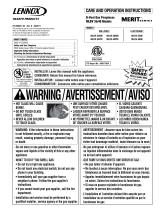
Test gauge connections are provided on the
front of the millivolt gas control valve (identi-
fied IN for the inlet and OUT for the manifold
side). The control valves have a 3/8" (10mm)
NPT thread inlet and outlet side of the valve
(refer to Figure 1).
Propane tanks are at pressures that will cause
damage to valve components. Verify that the
tanks have step down regulators to reduce the
pressure to safe levels.
Gas Valve Diagrams
See Figure 1 for Millivolt models.
Manifold Gas Supply Pressure
Fuel # Low High
Natural
Gas
2.2" WC
(0.55 kPa)
3.5" WC
(0.87 kPa)
Propane*
6.3" WC
(1.57 kPa)
10.0" WC
(2.49 kPa)
Table 3
*if field converted
Orifice Sizes - Sea Level to High Altitude
(All Models)
These appliances are tested and approved for
installation at elevations of 0-4500 feet (0-1372
meters) above sea level using the standard burner
orifice sizes (marked with an "*" in Table 4). For
elevations above 4500 feet, contact your gas
supplier or qualified service technician.
Deration - At higher elevations, the amount
of BTU fuel value delivered must be reduced
by either:
• Using gas that has been derated by the gas
company.
• By changing the burner orifice to a smaller
size as regulated by the local authorities
having jurisdiction and by the (USA) National
Fuel Gas Code NFPA 54/ANSI Z223.1 - latest
edition or, in Canada, the CAN/CGA-B149.1
codes - latest edition.
Install the appliance according to the regulations
of the local authorities having jurisdiction and,
in the USA, the National Fuel Gas Code NFPA
54 / ANSI Z223.1 - latest edition or, in Canada,
the CAN/CGA-B149.1 - latest edition.
Flame breadth, height and width will diminish
4% for every 1,000 feet of altitude.
In Canada - CAN/CGA-2.17-M91 (R2009) (high
altitude): THE CONVERSION SHALL BE CAR-
RIED OUT BY A MANUFACTURER’S AUTHO-
RIZED REPRESENTATIVE, IN ACCORDANCE
WITH THE REQUIREMENTS OF THE MANU-
FACTURER, PROVINCIAL OR TERRITORIAL
AUTHORITIES HAVING JURISDICTION AND
IN ACCORDANCE WITH THE REQUIREMENTS
OF THE CAN/CGA-B149.1 OR CAN/CGA-B149.2
INSTALLATION CODES.
REQUIREMENTS FOR THE COMMON-
WEALTH OF MASSACHUSETTS
These appliances are approved for installation in
the US state of Massachusetts if the following
additional requirements are met:
• Install this appliance in accordance with
Massachusetts Rules and Regulations 248
C.M.R. Sections 4.00 through 8.00.
• Installation and repair must be done by a
plumber or gas fitter licensed in the Com-
monwealth of Massachusetts.
• The flexible gas line connector used shall
not exceed 36 inches (92 centimeters) in
length.
• The individual manual shut-off must be a
T-handle type valve.
Inlet Gas Supply Pressure
Fuel # Minimum Maximum
Natural Gas
4.5" WC
(1.12 kPa)
10.5" WC
(2.62 kPa)
Propane*
11.0" WC
(2.74 kPa)
13.0" WC
(3.24 kPa)
Table 2
*if field converted
Gas Pressure - All Models
Tables 2 and 3 show the appliances' inlet and
manifold gas pressure requirements:
The appliance and its appliance main gas
valve must be disconnected from the gas
supply piping system during any pressure
testing of that system at test pressures in
excess of 1/2 psi (3.5 kPa).
The appliance must be isolated from the
gas supply piping system by closing its
equipment shutoff valve during any pressure
testing of the gas supply piping system at
test pressures equal to or less than 1/2 psi
(3.5 kPa).
H
I
L
O
W
HTPTHTPT
P
I
L
O
T
P
I
L
O
T
O
N
it
O
F
F
IN
OUT
HI/LO Variable
Flame Height
Adjustment
Figure 1 - SIT Millivolt Gas Valve
Manifold Pressure Tap
Inlet Pressure Tap
Pilot Adjustment
Screw
Main Gas Control Knob
OFF/PILOT/ON
Burner Orifice Sizes (all models)
Elevation
Feet (meters)
Natural
Gas
drill size (inches)
Propane
Gas**
drill size (inches)
0-4500
(0-1372)
#32 (0.116")
*
37L82 •
1.65mm (.065")
**
74L88 •
Table 4
* Standard size installed at factory
**If field converted.
• Part /Cat. Number
Input (BTU) Gas Valves (all models)
All Models Fuel Type Input Rate (BTU / HR)
Millivolt Natural 37,500 high - 30,000 low
Millivolt Propane 34,000 high - 27,000 low
Table 1
Millivolt Models - The millivolt appliances are
manually controlled and feature a spark igniter
(piezo) that allows the appliance's pilot gas to
be lit without the use of matches or batteries.
This system provides continued service in the
event of a power outage. A manually-modulated
gas valve is standard. Flame appearance and heat
output can be controlled at the gas valve. The BTU
Input for these appliances is shown in Table 1.
The appliance, when installed, must be electri-
cally grounded and wired in accordance with
local codes or, in the absence of local codes,
with the National Electrical Code, ANSI/NFPA
70 - latest edition, or the Canadian Electrical
Code, CSA C22.1 - latest edition.
Provide adequate clearances around air open-
ings and adequate accessibility clearance for
service and proper operation. Never obstruct
the front or back openings of the appliance.
These appliances are designed to operate
on natural gas only. The use of other fuels or
combination of fuels will degrade the perfor-
mance of this system and may be dangerous.
These fireplaces are designed as decorative appli-
ances and are not intended for use as area heaters.
They must Not be equipped with wall thermostats
or remote controls with thermostat functions.
These appliances must not be connected to a
chimney or flue serving a separate solid fuel
burning appliance.
The appliance area be kept clear and free from
combustible materials, gasoline and other
flammable vapors and liquids.

7
NOTE: DIAGRAMS & ILLUSTRATIONS ARE NOT TO SCALE.
General Information
900301-00 08/2018
Innovative Hearth Products
BRT40ST See-Through B-Vent Gas Fireplaces
COLD CLIMATE INSULATION
For cold climate installations, seal all cracks
around your appliance with noncombustible
material and wherever cold air could enter
the room. It is especially important to insulate
outside chase cavity between studs and under
floor on which appliance rests, if floor is above
ground level. Gas line holes and other open-
ings should be caulked or stuffed with unfaced
fiberglass insulation.
If the fireplace is being installed on a cement
slab in cold climates, a sheet of plywood or
other raised platform can be placed underneath
to prevent cold transfer to the fireplace and into
the room. It also helps to sheetrock inside
surfaces and tape for maximum air tightness
and caulk firestops.
MANUFACTURED HOUSING
B-Vent Fireplaces are not approved for use in
OEM or aftermarket manufactured housing built
to HUD standards.
LOCATION
In selecting the location, the aesthetic and
functional use of the appliance are primary
concerns. However, vent system routing to
the exterior and access to the fuel supply are
also important.
Due to high temperatures, the appliance
should be located out of traffic and away from
furniture and draperies (Figure 2).
En raison des températures élevées,
l’appareil devrait être installé dans un endroit
où il y a peu de circulation et loin du mobilier
et des tentures (Figure 2).
The location should also be free of electrical,
plumbing or other heating/air conditioning
ducting.
Be aware that this is a heat producing ap-
pliance. Objects placed above the unit are
exposed to elevated temperatures.
Do not insulate the space between the appli-
ance and the area above it.
The appliance must be mounted on a fully sup-
ported base extending the full width and depth of
the unit. The appliance may be located on or near
conventional construction materials. However,
if installed on combustible materials, such as
carpeting, vinyl tile or other combustible material
other than wood flooring, the appliance shall be
installed on a metal or wood panel extending the
full width and depth of the appliance.
Figure 2 - Typical Locations
Offset Venting
** When the see-through
fireplace is installed in the
middle of a room, do not
extend side walls beyond
either viewing side of the
fireplace.
* When the see-through
fireplace is installed with one
side flush with a wall, the op-
posite wall must not extend
beyond either viewing side of
the fireplace.
**See-Through
* See-Through
side flush with
a wall
Vertical Venting

8
NOTE: DIAGRAMS & ILLUSTRATIONS ARE NOT TO SCALE.
General Information
900301-00 08/2018
Innovative Hearth Products
BRT40ST See-Through B-Vent Gas Fireplaces
Figure 4
Figure 3
Vertical Vent Termination Clearances
VENT TERMINATION CLEARANCES
These instructions should be used as a
guideline and do not supersede local codes
in any way. Install venting according to local
codes, these instructions, the current National
Fuel Gas Code (ANSI-Z223.1) in the USA or
the current standards of CAN/CGA-B149.1
in Canada.
Vertical Vent Termination Clearances
Gas Vent Rule - Gas vent caps are not permitted
within 8 ft. (2.4 m) of a vertical wall or similar
obstruction. Gas vent caps that are located 8
ft. or more from a portion of a building which
extends at an angle greater than 45° upward
from the horizontal may terminate in accordance
with Figure 4 , provided that in no case shall
any discharge opening on the cap be less than
2 ft. (.6 m) horizontally from the roof surface
(National Fuel Gas Code ANSI Z223.1 (NFPA
54) (CAN/CGA B149.1).
Multiple Terminations
These appliances may vent adjacent to and at
the same level with any other gas appliances
(including direct-vent appliances) provided that
there is at least 2 ft. (0.6m) between the proximal
edges of the vent caps. These appliances may
be vented adjacent to a chimney vent servicing
a solid fuel fireplace provided the B-vent cap
is at least 2 ft. (0.6m) away from the nearest
point of the chimney opening.
Termination Heights For Vents
Above Flat Or Sloped Roofs
Ref. NFPA 54 / ANSI Z223.1
Roof Pitch * Feet * Meters
Flat to 6/12 1.0 0.3
6/12 to 7/12 1.25 0.38
7/12 to 8/12 1.5 0.46
8/12 to 9/12 2.0 0.61
9/12 to 10/12 2.5 0.76
10/12 to 11/12 3.25 0.99
11/12 to 12/12 4.0 1.22
12/12 to 14/12 5.0 1.52
14/12 to 16/12 6.0 1.83
16/12 to 18/12 7.0 2.13
18/12 to 20/12 7.5 2.29
20/12 to 21/12 8.0 2.44
The vent / air intake termination clearances
above the high side of an angled roof is as
shown in the following chart:
Roof Pitch is X/12
12
X
Minimum Height from Roof
to Lowest Discharge Opening
Multiple Terminations
2 ft.
(0.6m)
Minimum

9
NOTE: DIAGRAMS & ILLUSTRATIONS ARE NOT TO SCALE.
General Information
900301-00 08/2018
Innovative Hearth Products
BRT40ST See-Through B-Vent Gas Fireplaces
*NOTE: 3" (77 mm) above any inclined vent component.
**NOTE: See Page 11, Step 1 and Figure 8 for clearance requirements
to the nailing flange located at each side of the unit and any screw
heads adjacent to it.
Hearth Extension - A hearth extension is not required with this appliance.
If a hearth extension is used, do not block the lower control compartment
door. Any hearth extension used is for appearance only and does not
have to conform to standard hearth extension installation requirements.
Wall Finishes / Surrounds / Mantels
NOTE: Combustible wall finish materials and/or surround materials must
not be allowed to encroach the area defined by the appliance front face
(black sheet metal). Never allow combustible materials to be positioned
in front of or overlapping the appliance face (see Figure 6 on Page 9
and Figure 27 on Page 22).
Non-combustible materials, such as surrounds and other appliance trim,
may be installed on the appliance face with these exceptions: they must not
cover any portion of the removable glass panel or control compartment.
Vertical installation clearances to combustible mantels vary according
to the depth of the mantel. See Figure 5. Mantels constructed of non-
combustible materials may be installed at any height above the appliance
opening; however, do not allow anything to hang below the fireplace hood.
Minimum clearance requirements include any projections such as shelves,
window sills, mantels, etc. above the appliance.
NOTE: To avoid heat-related finish damage, we recommend the use of high
temperature paint (rated 175° F or higher) on the underside of the mantel.
MINIMUM CLEARANCES TO COMBUSTIBLES
Appliance And Vent Clearances
The appliance is approved with zero clearance to combustible materials
on all sides (as detailed in Table 5), with the following exception: When
the unit is installed with one side flush with a wall, the wall on the
other side of the unit must not extend beyond the front edge of the
unit (see Figure 2).
MINIMUM CLEARANCES* Inches (millimeters)
Back and Sides 1/2" (13)
0 (0) from Spacers Or Dimples **
Top Spacers 0 (0)
Floor 0 (0)
From Bottom of Unit To Ceiling 64 (1626)
Vent 3 (77) Top* / 1 (26) Sides & Bottom
SERVICE CLEARANCES Feet (meters)
Front, Back, Sides
3 feet (0.9 meters)
Table 5
Figure 6 - Minimum Distance to Unprotected Side Wall
4 (102)
2
(51)
4
(102)
6
(152)
8
(203)
10
(254)
12
(305)
6 (152)
10 (254)
14 (356)
12 (305)
8 (203)
inches (millimeters)
Top of
Appliance
Figure 5 - Minimum Mantel Clearances
Mantel Depth
Front or Rear Face
of Appliance
Min. Distance To
Protected Side Wall
Side
Wall
Side
Wall
Min. Distance To
Unprotected Side Wall
5"
14"
8-1/4"
45°
17"
12"
Combustible Materials Allowed
In Shaded Area Safe Zone
Top View of
Fireplace

10
NOTE: DIAGRAMS & ILLUSTRATIONS ARE NOT TO SCALE.
Installation
900301-00 08/2018
Innovative Hearth Products
BRT40ST See-Through B-Vent Gas Fireplaces
The appliance is shipped with all gas controls
and components installed and pre-wired.
1. Remove the shipping carton.
2. Remove hood buy pulling away from unit
(see Figure 7).
3. Remove front face assembly and barrier by
lifting approimately 1/2" and pulling away
from unit (see Figure 7).
4. Remove the modesty panel by pulling the
bottom right corner of the modesty panel
out slightly to disengage the snap-fit fea-
ture; lift the modesty panel by the tab on
the panel's right end, pull the right end of
the panel away from the cabinet and then
pull the panel diagonally out of the left side
cabinet panel slots. Remove the modesty
panel carefully, so that none of the wires
become loose or disconnected.
5. Open the latch (located under the firebox
floor) securing the glass enclosure panel.
Remove the panel by tilting it outward at
the bottom and lifting it up. Set the door
aside protecting it from inadvertent damage.
See Figure 24 on Page 21.
6. Remove log set box from firebox. Next,
remove embers, vermiculite and volcanic
stone from control compartment. Handle
logs carefully to prevent breakage.
Control Compartment Access Panel
Figure 7 - Unit Parts Identification
Front face assembly
Barrier
Control Compartment (behind assembly)
Hood
Figure 8 - Nailing Flanges
TYPICAL INSTALLATION SEQUENCE
The typical sequence of installation is outlined
below. However, each installation is unique and
may result in variations to the steps described.
See the page numbers references in the follow-
ing steps for detailed procedures.
Step 1. (Page 11) Construct the appliance
framing. Position the appliance within the
framing and secure with nailing brackets and
floor anchor tabs.
Step 2. (Page 13) Route gas supply line to
appliance location.
Step 3. (Page 13) Install the vent system and
exterior termination.
Step 4. (Page 14) Field Wiring
a. Millivolt Appliances - The operating control
switch is factory installed.
Step 5. (Page 15) Make connection to gas
supply.
Turn tabs down and secure to the floor with
8d nails or other appropriate fasteners
on all sides of the unit which do not have
viewing glass panels.
EDVST SHOWN
(EDVPF - NO NAILING FLANGES
ON END WITH GLASS PANEL)
EDVCL SHOWN
(FOR EDVCR VIEW, INTERCHANGE SIDES)
Remove these two screws and
use them when installing
the nailing flanges.
Nailing Flanges
Note: The nailing flanges, combustible members and screw heads located in areas directly adjacent to the nailing
flanges, are EXEMPT from the 1/2” clearance to combustible requirements for the firebox outer wrapper
.
Combustible framing may be in
direct contact with the nailing flanges and may be located closer than 1/2” from
screw heads and the firebox wrapper in areas adjacent to the nailing flanges. Frame the opening to the exact
dimensions specified in the framing details of this manual.
Turn tabs down and secure to the floor w
ith
8d nails or other appropriate fasteners on all sides
of the unit which do not have viewing glass panels.
Remove these two screws and
use them when installing
the nailing flanges.
Nailing
Flanges
PRE-INSTALLATION STEPS
Step 6. (Page 16) Install and verify outside
air kit operation.
Step 7. (Page 17) Checkout appliance opera-
tion.
Step 8. (Page 18) Install the log set, vermicu-
lite, volcanic stone and glowing embers.
Step 9. (Page 21) Removing and Installing
glass enclosure panels.
Step 10. (Page 21) Adjust burner primary air
shutter to achieve proper flame appearance.
Step 11. (Page 22) Install front face assembly
with barrier and hoods.
Step 12. (Page 23) Conduct limit switch
spillage test.
Step 13. (Page 24) Attach safety in operation
warnings.
NOTE: Front Face Assembly with
barrier installed must be rein-
stalled prior to operation.

11
NOTE: DIAGRAMS & ILLUSTRATIONS ARE NOT TO SCALE.
Installation
900301-00 08/2018
Innovative Hearth Products
BRT40ST See-Through B-Vent Gas Fireplaces
Gas Line
Center of gas line
is 3” (76 mm)
up from floor.
*41-1/2
(1054)
41-1/2
(1054)
22-3/4**
(578)
(See-Through)
inches (millimeters)
6-7/8
(175)
Minimum Framing
Stud size is 2 x 4
Figure 9 - Fireplace Framing Specifications
Step 1. FRAMING
Frame this appliance as illustrated in Figure 9.
All framing details must allow for a minimum
clearance to combustible framing members as
shown inTable 5 on Page 9. If the appliance is to
be elevated above floor level, a solid continuous
platform must be constructed. Headers may be
in direct contact with the appliance top spacers
but must not be supported by them or notched
to fit around them. All construction above the
appliance must be self supporting, DO NOT use
the appliance for structural support.
Side Nailing Flanges
The fireplace should be secured to the framing
at the side(s) and/or rear of the unit using the
factory-provided nailing flanges. Install the 8
nailing flanges as shown in Figure 8 using the
existing screws.
Position the fireplace within the framing. When
required, the flanges may be bent 90 degrees by
hand or with the assistance of a hammer. Use
wood screws to secure the nailing flanges to
the framing. See Table 5 on Page 9 for clear-
ances of framing members to cabinet parts in
the nailing flange area. The nailing flange itself
is exempt from these clearances.
Floor Nailing Tabs
Secure the fireplace to the floor as shown in
Figure 8.
*This dimension can be reduced to 41" (1041 mm). This results in 0" (0mm) clear-
ance between framing and unit framing spacers (The 41-1/2" dimension permits
easier fireplace installation, if unit is installed after framing is erected).
** Based on 5/8” drywall. Use 23" for 1/2" drywall.

12
NOTE: DIAGRAMS & ILLUSTRATIONS ARE NOT TO SCALE.
Installation
900301-00 08/2018
Innovative Hearth Products
BRT40ST See-Through B-Vent Gas Fireplaces
Inches (millimeters)
FIREPLACE SPECIFICATIONS
Figure 10
(See-Through)
48 (1219)
48-1/4 (1200)
37-3/4 (959)
40-1/4 (1022)
41
(1041)
37
(940)
34-1/8
(867)
23-1/2
(597)
27-3/4 (705)
23-7/8 (607)
41
(1041)
2 (51)
FRAMING
SPACERS
(Top and
both sides)
FINISHED WALL BRACKET
(Front and back edge of unit top)
Stepped to accept drywall
on all four corners
1/2
(13)
DETAIL OF
FINISHED
WALL BRACKET
GAS INLET
CONTROL
COMPARTMENT
ACCESS PANEL
TOP VIEW
FRONT VIEW SIDE VIEW
ELECTRICAL
INLETS
4-9/16
(116)
OUTSIDE AIR
SHUTTER
Hood
(both sides)

13
NOTE: DIAGRAMS & ILLUSTRATIONS ARE NOT TO SCALE.
Installation
900301-00 08/2018
Innovative Hearth Products
BRT40ST See-Through B-Vent Gas Fireplaces
Schedule 40
Black Iron Pipe
Inside Diameter (Inches)
Schedule 40 Pipe
Length (feet)
Natural
Gas
Propane
Gas
0-10 1/2 3/8
10-40 1/2 1/2
40-100 1/2 1/2
100-150 3/4 1/2
150-200 3/4 1/2
Table 6
Proper Sizing of Gas Line
Properly size and route the gas supply line
from the supply regulator to the area where the
appliance is to be installed per requirements
outlined in the National Fuel Gas Code, NFPA
54 - latest edition (USA) or CAN/CGA-B149.1
- latest edition (Canada).
Never use galvanized or plastic pipe. Refer to
Table 6 for proper sizing of the gas supply line,
if black iron pipe is being used. Gas lines must
be routed, constructed and made of materials
that are in strict accordance with local codes
and regulations. We recommend that a qualified
individual such as a plumber or gas fitter be
hired to correctly size and route the gas supply
line to the appliance.
Installing a gas supply line from the fuel supply to
the appliance involves numerous considerations
of materials, protection, sizing, locations, con-
trols, pressure, sediment, and more. Certainly no
one unfamiliar and unqualified should attempt
sizing or installing gas piping.
Step 2. ROUTING GAS LINE
Route a 1/2" (13 mm) gas line to the left side
of the appliance as shown in Figure 11. Gas
lines must be routed, constructed and made
of materials that are in strict accordance with
local codes and regulations. All appliances
are factory-equipped with a flexible gas line
connector and 1/2" shutoff valve. (See Step
5 on Page 14).
NOTES:
• All appliances are factory-equipped with a
flexible gas line connector and 1/2" shutoff
valve.
• See Massachusetts Requirements on Page 6
for additional requirements for installations
in the state of Massachusetts in the USA.
• The gas supply line should Not be connected
to the appliance until Step 5 (Page 15).
• A pipe joint compound rated for gas should be
used on the threaded joints. Ensure propane
resistant compounds are used in propane
applications. Be very careful that the pipe
compound does not get inside the pipe.
• It is recommended to install a sediment
trap in the supply line as close as possible
to the appliance. Appliances using Propane
should have a sediment trap at the base of
the tank.
• Check with local building official for local
code requirements (i.e. are below grade
penetrations of the gas line allowed?, etc).
IMPORTANT: If propane is used, be aware that
if tank size is too small (i.e. under 100-lbs, if
this is the only gas appliance in the dwelling.
Ref. NPFA 58), there may be loss of pressure,
resulting in insufficient fuel delivery (which
can result in sooting, severe delayed ignition
or other malfunctions). Any damage resulting
from an improper installation, such as this, is
not covered under the limited warranty.
Also see Figures 9 through 11
Figure 11 - Route Gas Line
5-5/8"
(143 mm)
3-1/8"
(79 mm)
6-7/8"
(175)
3"
(77)
Step 3. INSTALL THE VENT SYSTEM
General Information
These instructions should be used as a
guideline and do not supersede local codes
in any way. Install venting according to local
codes, these instructions, the current National
Fuel Gas Code (ANSI-Z223.1) in the USA or
the current standards of CAN/CGA-B149.1
in Canada.
Ensure clearances are in accordance with
local installation codes and the requirements
of the gas supplier.
Dégagement conforme aux codes d'installation
locaux et aux exigences du foumisseunde gaz.
These fireplaces must be vented directly
to the outside.
The vent system may not service multiple
appliances, and must never be connected to a
flue serving a solid fuel burning appliance. The
vent pipe is tested to be run inside an enclosed
wall (such as a chase). There is no requirement
for inspection openings in the enclosing wall at
any of the joints in the vent pipe.
In the United States, vent installation must
conform with local building codes. In the ab-
sence of local codes, vents must be installed
in accordance with the current edition of the
National Fuel Gas Code (ANSI-Z223.1).
In Canada, vent installation must conform with
local building codes. In the absence of local
codes, vents must be installed in accordance
with the current edition of the National Stan-
dard of Canada CAN/CGA-B149.1 or B149.2
Installation Code.
This gas fireplace must be vertically vented
using listed 6" type-B, double-walled vent
pipe and a listed vent termination.

14
NOTE: DIAGRAMS & ILLUSTRATIONS ARE NOT TO SCALE.
Installation
900301-00 08/2018
Innovative Hearth Products
BRT40ST See-Through B-Vent Gas Fireplaces
10 ft.
Minimum
12 ft.
Minimum
60 degrees
max.
Slip the first 6" (152 mm) section of B-Vent over
the fireplace flue outlet and secure with four
sheet-metal screws (# 8 or larger), and install
the remainder of the B-Vent to the outside.
Minimum overall height of the vent system and
appliance must be 10' (2.54 m) vertical - no
offset (see Figure 12); or 12' (3.7 m) when
an offset up to 60 degrees from the vertical is
used - this offset may start at the fireplace flue
collar (see Figure 13). The maximum overall
height of the vent system and appliance should
not exceed 40 feet.
Install the B-vent system in accordance with
the vent manufacturer's instructions.
CAUTION: THIS APPLIANCE CANNOT BE
VENTED HORIZONTALLY.
NOTE: Refer to the vent manufacturers instal-
lation instructions for variations of venting
techniques. If common venting of several units
is contemplated, it should be discussed with an
architect and the local Building Department.
Do not place insulation materials within 1" of
the gas vent system.
Figure 12
Figure 13
Step 4. FIELD WIRING
Figure 14 - Millivolt Wiring Diagram
Refer to Section A for millivolt appliances. The
gas valve is set in place and pre-wired at the
factory on both models.
A. Millivolt Wiring (See Figure 14)
Install Optional Control Switch (OFF/ON wall
switch or remote control receiver). Install snap
bushing (on brown wall switch wire) into control
switch knock-out in side panel (see Figure 10).
Wire the optional control switch within the mil-
livolt control circuit (as shown in Figure 14)
using the 15 feet of brown 2-conductor wire
supplied (route wires through the snap bush-
ing to the optional control switch). Mount the
optional control switch in a convenient location
on a wall near the fireplace.
CAUTION: Label all wires prior to disconnec-
tion when servicing controls. Wiring errors can
cause improper and dangerous operation.
ATTENTION: Au moment de l'entretien des
commandes, étiquetez tous les fils avant de
les débrancher. Des erreurs de cáblage peu-
vent entraîner un fonctionnement inadéquat
et dangereux.
Verify proper operation after servicing.
S'assurer que l'appareil fonctionne adé-
quatement une fois l'entretien terminé.
CAUTION
Do not connect optional control
switch to 120 VAC power supply.
* Control Switches: Wall On/Off Switch or Timer, Unit
Mounted On/Off Switch, or Remote Control Switch. If an
optional control switch is installed, turn the appliance-
mounted ON/OFF burner control switch to the OFF position.
VERIFY PROPER OPERATION AFTER
SERVICING.
If any of the original wire as supplied must be
replace, it must be replaced with type AWM
105° C - 18 gage wire.
HIGH LIMIT SWITCH
CONTROL SWITCH*
GAS CONTROL VALVE
TERMINALS
THERMOPILE
H
I
L
O
W
P
I
L
O
T
P
I
L
O
T
O
N
ti
O
F
F
IN
OUT
TH
TP HTP
T
Schematic Representation Only

15
NOTE: DIAGRAMS & ILLUSTRATIONS ARE NOT TO SCALE.
Installation
900301-00 08/2018
Innovative Hearth Products
BRT40ST See-Through B-Vent Gas Fireplaces
Figure 15 - GAS CONNECTION
Make gas line connections. All codes require a
shut-off valve mounted in the supply line. Figure
15 illustrates two methods for connecting the
gas supply. The flex-line method is acceptable
in the U.S., however, Canadian requirements
vary depending on locality. Installation must
be in compliance with local codes.
A sediment trap is recommended in the gas
piping within the home to prevent moisture
and debris in the line from damaging the valve.
These appliances are equipped with a gas flex
line for use (where permitted) in connecting the
unit to the gas line. A gas flex line is provided to
aid in attaching the appliance to the gas supply.
The gas flex line can only be used where local
codes permit.
The flex line is rated for both natural and propane
gas. A manual shut off valve is also provided with
the flex line. The gas control valve is located in
the lower control compartment.
To access the valve open the lower control
compartment door (see Figure 17 ) by pushing
in the right top corner of the door. (The door
is hinged at the bottom). Remove the bottom
compartment door by sliding the hinge pin,
located at the door’s left side, to the right until
it disengages from the left corner post hole.
Pull the door diagonally to the left, away from
the fireplace.
The lower control compartment door on the
side opposite the valve lifts on and off.
The millivolt control valve has a 3/8"
(10 mm) NPT thread inlet port.
Secure all joints tightly using appropriate
tools and sealing compounds (ensure propane
resistant compounds are used in propane
applications).
All codes require a shut-off valve mounted in
the supply line. The orientation of the shut-off
valve should face the front. Figure 15 illustrates
two methods for connecting the gas supply.
A sediment Trap is recommended to prevent
moisture and debris in the gas line for damag-
ing the valve.
NOTE: Using a soapy water solution is an
effective leak test solution but it is not recom-
mended, because the soap residue that is left
on the pipes/fittings can result in corrosion
over time.
WARNING
Never use an open flame to
check for leaks.
TEST ALL CONNECTIONS FOR GAS LEAKS
(FACTORY AND FIELD):
STEP 5. CONNECTING GAS LINE
Turn on gas supply and test for gas leaks, us-
ing a gas leak test solution (also referred to as
bubble leak solution).
A. Light the appliance (refer to the lighting
instructions label in the control compart-
ment or in the Installation and Operation
Instructions manual).
B. Brush all joints and connections with the gas
leak test solution to check for leaks. If bubbles
are formed, or gas odor is detected, turn the
gas control knob (off/pilot/on) to the “OFF”
position. Either tighten or refasten the leaking
connection, then retest as described above.
C. When the gas lines are tested and leak free,
be sure to rinse off the leak testing solution.

16
NOTE: DIAGRAMS & ILLUSTRATIONS ARE NOT TO SCALE.
Installation
900301-00 08/2018
Innovative Hearth Products
BRT40ST See-Through B-Vent Gas Fireplaces
Outside Air Control Lever
and Securing Screw Location
Outside Air Control Lever with Stop Behind
Securing Screw
Outside Air Shutter in the
Closed Position
Control Compartment Access Panel
Figure 16
Step 6. OUTSIDE AIR KITS
Optional outside make-up air kits, Model FOAK-4
or FAOK-4LD, may be used with these appli-
ances. Refer to the installation instructions
packaged with the air kits for specific installation
information. If used, the outside air kit must
be installed before the fireplace is framed and
enclosed in the finished wall.
Outside air drawn into the fireplace supplies air
to the fire for combustion. Only one outside air
duct is necessary, if installed. See the Figure 11
for the location of the units outside air inlet.
If additional length of duct is necessary, pur-
chase locally available U.L. Class 0 or Class 1
metallic ducting. The duct may extend up to 50'
(15.24 m) in any direction.
NOTE: When installing the air duct vertically,
DO NOT terminate the duct closer than 3' below
the chimney top.
Outside combustion air ducting may be run
upwards or vertically through framing and ceil-
ing joists, with the hood installed through an
outside wall and 3' (1 m) below the termination.
Ducting may also be run downward through
floor Joists and under the home to a ventilated
crawlspace not considered part of the living
area of the home.
NOTE: Do not terminate outside air kit in attic
space under any circumstances.
CAUTION: NEVER LOCATE INLET WHERE IT
CAN BE BLOCKED BY SHRUBS, SNOW DRIFTS,
ETC. NEVER LOCATE INLET IN GARAGE OR
ANY AREA WHERE THERE IS ANOTHER FUEL
BURNING APPLIANCE OR PRODUCTS EMIT-
TING COMBUSTIBLE GASES SUCH AS PAINT,
GASOLINE, ETC. IN COLD CLIMATES, IT IS
RECOMMENDED THE COMBUSTION AIR DUCT
BE INSULATED.
After completing the installation of the optional
outside air vent system, the outside air control
lever must be put in service and tested to ensure
proper operation before completing any enclo-
sure around the firebox. Failure to do so may
result in extensive and costly rework.
Before the operation of the vent system can
be tested, the lever securing screw must be
removed. See Figure 16.
The hand operated outside air control lever
is located on the right side of the fireplace
opening. See Figure 16.
To open the outside air shutter, open the bottom
control access panel, reach into the gap between
the firebox bottom and the modesty panel, and
pull the outside air control lever all the way out.
The outside air shutter should be fully open when
the fireplace is in use and completely closed
when the fireplace is not being used. Closing
it when not in use will prevent outside cold air
from entering the dwelling.
Operate the actuator through several cycles
including the closed position. Ensuring proper
operation and freedom of movement. Return
the actuator arm to the closed position.

17
NOTE: DIAGRAMS & ILLUSTRATIONS ARE NOT TO SCALE.
Installation
900301-00 08/2018
Innovative Hearth Products
BRT40ST See-Through B-Vent Gas Fireplaces
Millivolt Appliance Checkout
The pilot flame should be steady, not lifting
or floating. Flame should be blue in color with
traces of orange at the outer edge.
The top 3/8" (10 mm) at the pilot generator
(thermopile) and the top 1/8" minimum (tip)
of the quick drop out thermocouple should be
engulfed in the pilot flame.
The flame should project 1" (26 mm) beyond
the hood at all three ports (see Figure 18).
Replace logs if removed for pilot inspection.
To light the burner; turn “ON” the remote wall
switch and rotate the gas valve control knob
counterclockwise to the “ON” position (“ON”
will be at the top side of the valve).
Figure 17
Piezo Igniter
Gas Valve
Modesty Panel
Control
Compartment
Access panel
ON/OFF
Switch
Hinge Pin
MILLIVOLT
Thermocouple
Hood Igniter Rod
3/8" Min
(9 mm)
Thermopile
Pilot
Nozzels
Figure 18
Step 7. VERIFYING APPLIANCE OPERA-
TION
Turn on burner and observe the individual
tongues of flame on the burner. Make sure
all ports are open and producing flame evenly
across the burner. If any ports are blocked, or
partially blocked, clean out the ports.
With gas line installed run initial system
checkout before closing up the front of the
unit. Follow the pilot lighting instructions
provided in the Installation and Operation
Instructions manual. For piezo igniter loca-
tion see Figure 17 (millivolt appliances only).
NOTE: Lighting Instructions are also found on
the literature tag tied to the gas piping next
to the gas valve. To access the tag, open the
lower control compartment door (Figure 17) by
pushing in simultaneously the left and right top
corners of the door. (The door is hinged at the
bottom). Remove the bottom compartment door
by sliding the hinge pin, located at the door’s
left side, to the right until it disengages from
the left corner post hole. Remove the modesty
panel. To remove the modesty panel, slide the
panel forward until it contacts the cabinet bot-
tom panel, then lift straight up and tilt forward.
Remove the modesty panel carefully, so that
none of the wires become loose or disconnected.
When first lighting the appliance, it will take a
few minutes for the line to purge itself of air.
Once purging is complete, the pilot and burner
will light and operate as indicated in the instruc-
tion manual.
Subsequent lighting of the appliance will not
require such purging. Inspect the pilot flame (re-
move logs, if necessary, handling carefully).

18
NOTE: DIAGRAMS & ILLUSTRATIONS ARE NOT TO SCALE.
Installation
900301-00 08/2018
Innovative Hearth Products
BRT40ST See-Through B-Vent Gas Fireplaces
Figure 19
Step 8. INSTALL VERMICULITE, GLOWING EMBERS AND LOGS
NOTE: It is important to ensure proper log placement per the manual
when installing these units. Verify pilot flame is not obstructed. See
Verifying Appliance Operation on Page 17.
NOTE: Turn off all electricity to the appliance before you install vermiculite,
embers and logs. DO NOT attempt to install the logs until the appliance
installation has been completed, the gas line connected and tested for
leaks and the initial burner operation has been checked out.
INSTALLATION STEPS:
READ WARNINGS ON THIS PAGE BEFORE PROCEEDING. FOLLOW THE
LOG PLACEMENT INSTRUCTIONS EXACTLY
1. Remove the front glass enclosure panel (see Glass Enclosure Panel
Removal and Installation Instructions, Page 21).
2. Remove the following from firebox; log set, bag of embers and bag
of vermiculite. Handle logs carefully to prevent breakage.
3. Ensure the Grate is properly installed in the firebox with the 4 legs
of the grate fitting into the 4 dimples on the firebox floor.
4. Placement of Glowing Embers -
Separate the Embers (rockwool) into pieces about the size of a quarter
(see Figure 19). Keep the pieces fluffed up, not matted. Distribute
these pieces over the surface of the burner, as shown in Figure 20.
Do not use more than is necessary. Ensure that the main burner ports
remain uncovered by the ember material.
5. Place Volcanic Stone - Spread volcanic stone evenly over firebox
floor.
6. Install Vermiculite - Place some vermiculite on the firebox floor around
the grate (the entire bag of vermiculite will NOT be used). DO NOT PLACE
ANY VERMICULITE ON THE BURNER.
NOTE: This appliance is provided with enough Glowing Embers for
several applications, do not use all that is in a new bag at one time. For
best glowing effect, replace the ember material annually. Replacement
Glowing Embers are available (order Catalog Number 88L53).
WARNING
• DO NOT attempt to install the logs until the appli-
ance installation has been completed, the gas
line connected and tested for leaks and the initial
burner operation has been checked out.
•
The size and position of the log set was engineered
to give the appliance a safe, reliable and attrac-
tive flame pattern. Any attempt to use a different
log set in the fireplace will void the warranty and
will result in incomplete combustion, sooting,
and poor flame quality.
•
Logs get very hot and will remain hot up to one
hour after gas supply is turned off. Handle only
when logs are cool. Turn off all electricity to the
appliance before you install grate, volcanic stone,
vermiculite, embers and logs.
•
This appliance is not designed to burn wood. Any
attempt to do so could cause irreparable damage
to the appliance and prove hazardous to your
safety.
•
If logs are not installed according to the log
installation instructions, flame impingement
and improper combustion could occur and result
in soot and/or excessive production of carbon
monoxide (CO), a colorless, odorless, toxic gas.
Glowing Embers
Figure 20
REFERENCE
Firebox Accessories / Parts
Cat. No. Model No. Description
88L53 FGE Bag of Glowing Embers
80L42 FDVS Bag of Decorative Volcanic Stone
H6319 ---- Bag of Vermiculite

19
NOTE: DIAGRAMS & ILLUSTRATIONS ARE NOT TO SCALE.
Installation
900301-00 08/2018
Innovative Hearth Products
BRT40ST See-Through B-Vent Gas Fireplaces
Log
Number
Description
1 Log, Corner
2 Log, Rear/Left
3 Log, Front/Left
4 Log, Rear/Right
5 Log, Front/Center
6 Log, Center/Top
BRT40ST LOG PLACEMENT
Figure 21
Catalog Number for the entire log set: 55M04
6
5
4
1
3
Position Groove At The
Bottom Of Log (1) Over
The Burner Log Support
Bracket
Position The Groove At The
Bottom Of Log (1) Over The
Grate And Slide It Forward
Against The Grate Here
Position Log (2) Over The Grate
Bar And Slide It Against The Back
Of The Grate Here
Position Groove At The Bottom Of Log (2)
Over The Grate Here And Slide It Against
The Back Of The Grate
Place Bottom Hole Of Log (3) On Pin In Log (2). Position
Grooves At The Bottom Of Log (3) Over The Grate.
1
Position And Slide Log (4)
Against The Back Of The Grate
2
Log (3) Lays Over Logs
1 And 2
STEP 1
STEP 2
STEP 3
STEP 4
3
4
1
Place Log (4) Over
The Flat Spot On
Log (1) Here
2

20
NOTE: DIAGRAMS & ILLUSTRATIONS ARE NOT TO SCALE.
Installation
900301-00 08/2018
Innovative Hearth Products
BRT40ST See-Through B-Vent Gas Fireplaces
Log
Number
Description
1 Log, Corner
2 Log, Rear/Left
3 Log, Front/Left
4 Log, Rear/Right
5 Log, Front/Center
6 Log, Center/Top
Figure 22
BRT40ST LOG PLACEMENT (CONTINUED)
Catalog Number for the entire log set: 55M04
2
6
5
4
1
3
3
Grate
Assembly
5
Position Small End Of Log (6)
On The Notch Of Log (3) Here
6
4
Position The Round End Of Log (6)
Against The Notch Of Log (4) Here.
Two Charred Spots Face The Front
Position The Groove In The Back
Of Log (3) Against The Grate
Rest Log (5) Against
The Grate Here
Log (5) Sits In Front
Of The Grate
STEP 5
NOTICE: BRT40ST model fireplaces
include barriers to reduce the risk of
burns from hot viewing glass. The
barriers in the fireplace are screens
shown right.
J7420 (40" Models)
WARNING
Any safety screen, guard, or
barrier removed for servicing
an appliance must be replaced
prior to operating the appliance.
NOTE:
• If the barrier becomes dam-
aged, the barrier shall be re-
placed with the manufacturer’s
barrier for this appliance.
• For use with barrier(s) Part
No(s). J7420.
Figure 23
1/52