Nilfisk-Advance BR 1100 Instructions For Use Manual
- Catégorie
- Machine à plancher
- Taper
- Instructions For Use Manual
Ce manuel convient également à

4/04 revised 6/05 Form Number 56041587
English
Hydro-Retriever
™
3800
Instructions For Use
BR 1100, 1100C, 1100C-XL
Hydro-Retriever
™
2042
Advance MODELS 56410000(disc), 56410350(cyl.), 56410001(2042)
Nilfi sk MODEL 56410002(disc), 56410351(cyl.), 56410425 (1100C-XL)
56307200(Haram BR 1100)


FORM NO. 56041587 - Hydro-Retriever
™
3800, 2042 / BR 1100, 1100C, 1100C-XL - 3
ENGLISH / 3
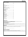
TABLE OF CONTENTS
page
Introduction ............................................................................................... 3
Cautions and Warnings ............................................................................4
Consignes de prudence et de sécurité .....................................................5
Know Your Machine ..................................................................................6
Control Panel ............................................................................................7
Functional Description of Control Buttons ................................................8
Description of Indicators on the Control Panel .........................................9
Prepare the Machine for Use
Install the Batteries .................................................................................10
Install the Brushes ..................................................................................11
Install the Squeegee ...............................................................................12
Fill the Solution Tank ..............................................................................12
Operating the Machine ...........................................................................13
Scrubbing ...............................................................................................13
Wet Vacuuming ......................................................................................14
After Use .................................................................................................14
Maintenance Schedule ...........................................................................14
Lubricating the Machine .........................................................................14
Charging the Batteries ............................................................................15
Check the Battery Electrolyte Level ........................................................15
Squeegee Maintenance ..........................................................................16
Squeegee Adjustment ............................................................................16
Side Skirt Maintenance ......................................................................17-18
Troubleshooting ...................................................................................... 19
Controller Error Codes .......................................................................20-21
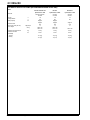
Technical Specifi cations .........................................................................22
INTRODUCTION
This manual will help you get the most from your Nilfi sk-Advance Rider Scrubber. Read it thoroughly before operating the machine.
Note: Bold numbers in parentheses indicate an item illustrated on pages 6-7.
This product is intended for commercial use only.
PARTS AND SERVICE
Repairs, when required, should be performed by your Authorized Nilfi sk-Advance Service Center, who employs factory trained service personnel, and main-
tains an inventory of Nilfi sk-Advance original replacement parts and accessories.
Call the NILFISK-ADVANCE DEALER named below for repair parts or service. Please specify the Model and Serial Number when discussing your machine.
NAME PLATE
The Model Number and Serial Number of your machine are shown on the Nameplate on the machine. This information is needed when ordering repair parts
for the machine. Use the space below to note the Model Number and Serial Number of your machine for future reference.
MODEL NUMBER _____________________________________________
SERIAL NUMBER _____________________________________________
UNCRATE THE MACHINE
When the machine is delivered, carefully inspect the shipping carton and the machine for damage. If damage is evident, save the shipping carton so that it
can be inspected. Contact the Nilfi sk-Advance Customer Service Department immediately to fi le a freight damage claim.
After removing the carton, cut the plastic straps and remove the wooden blocks next to the wheels. Use a ramp to roll the machine from the pallet to the fl oor.

4 - FORM NO. 56041587 - Hydro-Retriever
™
3800, 2042 / BR 1100, 1100C, 1100C-XL
4 / ENGLISH
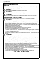
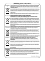
CAUTIONS AND WARNINGS
SYMBOLS
Nilfi sk-Advance uses the symbols below to signal potentially dangerous conditions. Always read this information carefully and
take the necessary steps to protect personnel and property.
DANGER !
Is used to warn of immediate hazards that will cause severe personal injury or death.
WARNING !
Is used to call attention to a situation that could cause severe personal injury.
CAUTION !
Is used to call attention to a situation that could cause minor personal injury or damage to the machine or other property.
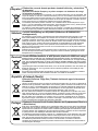
GENERAL SAFETY INSTRUCTIONS
Specifi c Cautions and Warnings are included to warn you of potential danger of machine damage or bodily harm.
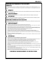
WARNING !
* This machine shall be used only by properly trained and authorized persons.
* While on ramps or inclines, avoid sudden stops when loaded. Avoid abrupt sharp turns. Use low speed down hills. Clean
only while ascending (driving up) the ramp.
* Keep sparks, fl ame and smoking materials away from batteries. Explosive gases are vented during normal operation.
* Charging the batteries produces highly explosive hydrogen gas. Charge batteries only in well-ventilated areas, away from
open fl ame. Do not smoke while charging the batteries.
* Remove all jewelry when working near electrical components.
* Turn the key switch off (O) and disconnect the batteries before servicing electrical components.
* Never work under a machine without safety blocks or stands to support the machine.
* Do not dispense fl ammable cleaning agents, operate the machine on or near these agents, or operate in areas where
fl ammable liquids exist.
* Do not clean this machine with a pressure washer.
* Only use the brushes provided with the appliance or those specifi ed in the instruction manual. The use of other brushes may
impair safety.
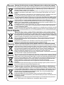
CAUTION !
* This machine is not approved for use on public paths or roads.
* This machine is not suitable for picking up hazardous dust.
* Do not use scarifi er discs and grinding stones. Nilfi sk-Advance will not be held responsible for any damage to fl oor surfaces
caused by scarifi ers or grinding stones (can also cause damage to the brush drive system).
* When operating this machine, ensure that third parties, particularly children, are not endangered.
* Before performing any service function, carefully read all instructions pertaining to that function.
* Do not leave the machine unattended without fi rst turning the key switch off (O), removing the key and applying the parking
brake.
* Turn the key switch off (O) and remove the key, before changing the brushes, and before opening any access panels.
* Take precautions to prevent hair, jewelry, or loose clothing from becoming caught in moving parts.
* Use caution when moving this machine in below freezing temperature conditions. Any water in the solution or recovery tanks
or in the hose lines could freeze, causing damage to valves and fi ttings. Flush with windshield washer fl uid.
* The batteries must be removed from the machine before the machine is scrapped. The disposal of the batteries should be
safely done in accordance with your local environmental regulations.
* Do not use on surfaces having a gradient exceeding that marked on the machine.
* All doors and covers are to be positioned as indicated in the instruction manual before using the machine.
SAVE THESE INSTRUCTIONS

FORM NO. 56041587 - Hydro-Retriever
™
3800, 2042 / BR 1100, 1100C, 1100C-XL - 5
ENGLISH / 5
CONSIGNES DE PRUDENCE ET DE SÉCURITÉ
SYMBOLES
Les symboles reproduits ci-dessous sont utilisés pour attirer l’attention de l’opérateur sur des situations dangereuses. Il est
donc conseillé de lire attentivement ces indications et de prendre les mesures adéquates en vue de protéger le personnel et le
matériel.
DANGER !
Ce symbole est utilisé pour mettre l’opérateur en garde contre les risques immédiats pouvant provoquer des dommages corpo-
rels graves, voire entraîner la mort.
AVERTISSEMENT !
Ce symbole est utilisé pour attirer l’attention sur une situation susceptible d’entraîner des dommages corporels graves.
ATTENTION !
Ce symbole est utilisé pour attirer l’attention de l’opérateur sur une situation qui pourrait entraîner des dommages corporels
minimes ou des dommages à la machine ou à d’autres équipements.
CONSIGNES GENERALES DE SECURITE
Les consignes spécifi ques de prudence et de sécurité mentionnées ici ont pour but de vous informer de la survenance de tout
risque de dommages matériels ou corporels.
AVERTISSEMENT !
* Cette machine ne pourra être utilisée que par du personnel parfaitement entraîné et dûment autorisé.
* Evitez les arrêts subits lorsque la machine est chargée et se trouve sur des rampes ou des plans inclinés. Evitez les virages serrés. Adoptez une
vitesse réduite lorsque la machine est en descente. Ne nettoyez que lorsque la machine monte la pente.
* Eloignez les batteries de toutes fl ammes, étincelles ou substance fumigène. Les gaz explosifs sont ventilés pendant le fonctionnement normal.
* De plus, du gaz hydrogène explosif s’échappe des batteries lorsqu‘elles sont en charge. Ne procédez au chargement des batteries que dans une
zone bien ventilée, loin de toute fl amme. Ne fumez pas à proximité des batteries lorsqu‘elles sont en charge.
* Otez tous vos bijoux lorsque vous travaillez à proximité de composants électriques.
* Positionnez la clé de contact sur off (O) et déconnectez les batteries avant de procéder à l‘entretien des composants électriques.
* Ne travaillez jamais sous une machine sans y avoir placé, au préalable, des blocs de sécurité ou des étais destinés à soutenir la machine
* Ne déversez pas d‘agents nettoyants infl ammables, ne faites pas fonctionner la machine à proximité de ces agents ou d‘autres liquides infl ammab-
les.
* Ne nettoyez pas cette machine avec un nettoyeur à pression.
* Utilisez uniquement les brosses fournies avec l’appareil ou celles spécifi ées dans le manuel d’instructions. L’utilisation d’autres brosses peut mettre
la sécurité en péril.
ATTENTION !
* Cette machine n’est pas conçue pour une utilisation sur les chemins ou voies publics.
* Cette machine n‘est pas conçue pour le ramassage des poussières dangereuses.
* N‘utilisez pas de disques de scarifi cateur ni de meules. Nilfi sk-Advance ne pourra en aucun cas être tenue pour responsable des dommages occasi-
onnés à vos sols par ce type d‘équipement (vous risquez également d‘endommager le système d‘entraînement des brosses).
* Lors de l‘utilisation de cette machine, assurez-vous que des tiers, et notamment des enfants, ne courent pas le moindre risque.
* Avant de procéder à toute opération d‘entretien, veuillez lire attentivement toutes les instructions qui s‘y rapportent.
* Ne laissez pas la machine sans surveillance sans avoir, au préalable, coupé le contact, enlevé la clé de contact (O) et tiré le frein à main.
* Positionnez la clé de contact sur off (O) avant de remplacer les brosses ou d’ouvrir tout panneau d’accès.
* Prenez toutes les mesures nécessaires pour éviter que les cheveux, les bijoux ou les vêtements amples ne soient entraînés dans les parties mobiles
de la machine.
* Faites attention lorsque vous déplacez cette machine dans un endroit où la température peut descendre sous 0°. Car l‘eau contenue dans les réser-
voirs de solution ou de récupération ou dans les conduites risquerait de geler et par là même d‘endommager les valves et raccords de la machine.
Rincez avec un liquide de lave-glace.
* Prenez soin d‘enlever les batteries de la machine avant de mettre cette dernière au rebut. Pour ce qui est de l‘élimination des batteries, conformez-
vous aux réglementations locales en matière d‘environnement.
* N’utilisez pas sur des surfaces dont la pente dépasse celle mentionnée sur la machine.
* Toutes les portes et couvercles doivent être dans la position mentionnée dans le manuel d’instruction avant de mettre la machine en service.
CONSERVEZ SOIGNEUSEMENT CES INSTRUCTIONS

6 - FORM NO. 56041587 - Hydro-Retriever
™
3800, 2042 / BR 1100, 1100C, 1100C-XL
6 / ENGLISH
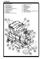
KNOW YOUR MACHINE
1 Recovery Tank Covers
2 Solution Tank Fill Cover
3 Operator Seat w/Safety Switch
4 Solution Tank Drain Hose
5 Steering Wheel Adj. Tilt Knob
6 Brake Pedal & Parking Brake Set/Release Lever
7 Solution Flow Control Lever
8 Drive Pedal Directional/Speed
9 Charger Plug
10 Drive and Steer Wheel
11 Circuit Breakers
12 Emergency Stop Switch / Battery Disconnect
13 Scrub Brush Deck And Side Skirts
14 Rear Wheel
15 Battery Compartment
16 Recovery Tank Shutoff Float
17 Vacuum Motor Filter Housing
18 Squeegee Assembly
19 Squeegee Casters
20 Solution Filter
21 Recovery Tank Drain Hose
44 Side Broom Wear Adjustment Lever (2042 / BR 1100C-XL only)
45 Operator Seat Adjustment Lever
1
2
3
5
6
7
8
9
10
11
12
13
14
15
16
17
18
19
21
20
4
44
45

FORM NO. 56041587 - Hydro-Retriever
™
3800, 2042 / BR 1100, 1100C, 1100C-XL - 7
ENGLISH / 7
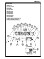
CONTROL PANEL
22 Horn Button
23 Main Power Indicator
24 Solution System Fault Indicator
25 Scrub Off Button
26 Normal Scrub Button
27 Heavy Scrub Button
28 Solution System Indicator
29 Vacuum Button
30 Solution Button
31 Battery Condition Indicator
32 Hourmeter/Status Display
33 Master On/Off Key Switch
34 Scrub Mode Off Indicator
35 Normal Scrub Mode Indicator
36 Heavy Scrub Mode Indicator
37 Vacuum System Indicator
38 Vacuum System Fault Indicator
39 Presweep Dust Control Button (3800 / BR 1100 only - opt)
40 Presweep Dust Control Indicator (3800 / BR 1100 only - opt)
41 Presweep Power Indicator (3800 / BR 1100 only - opt)
42 Sweep System Power Indicator (2042 / BR 1100C-XL only)
43 Sweep System Control Button (2042 / BR 1100C-XL only)
kg
lb
kg
lb
1/10
31
32
33
23
41
39
40
22
24
30
28
38
29
37
27
36
26
35
25
34
2042
42
43
1100C-XL

8 - FORM NO. 56041587 - Hydro-Retriever
™
3800, 2042 / BR 1100, 1100C, 1100C-XL
8 / ENGLISH
FUNCTIONAL DESCRIPTION OF CONTROL BUTTONS:
The controls were designed with one touch operation in mind. For single pass scrubbing the user can simply depress one button and all systems on the
machine will be ready to go.
For most single-pass scrubbing operations, the operator should only need to use the fi rst three buttons on the control panel. These are the Scrub Off (25),
Normal Scrub (26), and Heavy Scrub (27) buttons. For this reason these buttons are outlined in bright white on the control panel while the other buttons are
outlined in a darker color.
Horn Button (22) - Pressing this button will activate the horn.
Scrub Off Button (25) - Pressing this button when the unit is in a scrub mode will cause the following to occur:
• The scrub brushes will turn off
• The scrub deck will raise to the UP position
• The solution fl ow will be stopped
• The fi rst time that this button is pressed, the vacuum/squeegee system will NOT be turned off. This is so that any remaining water may be picked up
without having to turn the vacuum back on. If this button is pressed a second time (pressed after the scrub mode has been turned off) the squeegee will
raise and the vacuum will shut off after a 6 second delay.
Normal Scrub Button (26) - Pressing the normal scrub button will enable the scrub system and set the scrub pressure to the last selected value for the nor-
mal scrub mode. The status display will momentarily display the scrub pressure setting. This is indicated by “PA” followed by a number. Subsequent presses
of the normal scrub button will step the pad pressure setting through the allowable range up to the maximum value programmed for the normal scrub mode.
Once the maximum value is reached the pressure setting will step back to 1. The factory default maximum for the normal scrub mode is 4. The following will
occur when this button is pressed:
• The scrub deck will be lowered
• The vacuum and solution systems will be enabled (vacuum and solution modes = AUTO)
• As soon as a direction is commanded by the throttle (forward or reverse) the brushes will start turning and the vacuum will turn on. If the direction is
forward, the squeegee will lower and the solution fl ow will start. If the direction is reverse, the squeegee will go to the up position and the solution fl ow will
be stopped.
Heavy Scrub Button (27) - Pressing the heavy scrub button will enable the scrub system and set the scrub pressure to the last selected value for the heavy
scrub mode. The status display will momentarily display the scrub pressure setting. This is indicated by “PA” followed by a number. Subsequent presses
of the heavy scrub button will step the pad pressure setting through the allowable range up to the maximum value programmed for the heavy scrub mode.
Once the maximum value is reached the pressure setting will step back to (normal scrub limit + 1). The factory default maximum for the heavy scrub mode is
7 (cylindrical) or 9 (disc). The following will occur when this button is pressed:
• The scrub deck will be lowered
• The vacuum and solution systems will be enabled (vacuum and solution modes = AUTO)
• As soon as a direction is commanded by the throttle (forward or reverse) the brushes will start turning and the vacuum will turn on. If the direction is
forward, the squeegee will lower and the solution fl ow will start. If the direction is reverse, the squeegee will go to the up position and the solution fl ow will
be stopped.
Vacuum Button (29) - This button is used to select the mode of operation for the vacuum/squeegee system. There are 3 modes of operation for this system.
These modes are OFF, AUTO, ON. Following is a description of each mode and how they are selected.
OFF MODE: In this mode the vacuum is off and the squeegee is in the up position. As mentioned above, when a scrub mode is selected, the vacuum
system will be placed in the AUTO mode. If it is desired to double-scrub (scrub without recovering the solution) the vacuum system can be turned off by
pressing this button.
AUTO MODE: This mode is automatically selected when a scrub mode is selected. In this mode the squeegee will be in the down position unless the re-
verse direction is selected via the throttle. The vacuum will turn on if either direction is selected. While in this mode the vacuum will remain on for 10 seconds
after the throttle returns to the neutral position. This is so that the solution in the squeegee and hose can be drawn into the tank. This mode can be selected
independently of the scrub mode by pressing and releasing the vacuum button.
ON MODE: In this mode the squeegee will remain in the UP position and the vacuum will be on regardless of the throttle position. This mode is selected
by pressing and holding the vacuum button for approximately 1.5 seconds. The vacuum mode must fi rst be OFF before entering this mode. This mode is
included in the event an external wand is to be used with this machine or if the operator wants to clean the squeegee using the vacuum hose.
Solution Button (30)
- This button is used to select the mode of operation for the solution system. There are 3 modes of operation for this system. The
modes are OFF, AUTO, MOMENTARY ON. Following is a description of each mode and how they are selected.
OFF MODE: In this mode the solution fl ow is turned off. As mentioned above, when a scrub mode is selected, the solution system will be placed in the
AUTO mode. If it is desired to scrub without dispensing solution, the solution can be turned off by pressing this button.
AUTO MODE: This mode is automatically selected when a scrub mode is selected. In this mode the solution fl ow will be turned on whenever the forward
direction is selected via the throttle. The solution fl ow will be turned off otherwise.
MOMENTARY ON MODE: This mode can only be selected when the scrub mode is OFF. Solution can be dispensed by pressing and holding the solution
button. Solution will be dispensed for as long as the button is held. This is for pre-wetting the fl oor prior to scrubbing.
Presweep Dust Control Button (opt / 39) - Use this button in conjunction with the optional presweep kit. The dust control feature will only work when the
brooms are running on the presweep unit.
Sweep System Control Button (2042 / BR 1100C-XL only) (43) - Use this button to turn the sweep system ON or OFF. The side brooms will only run when
the scrub system is ON and the machine is in motion (not in neutral). If the scrub system is turned OFF while the sweep system is still ON, the side brooms
will automatically lower and run the next time the scrub system is turned ON.
Side Broom Wear Adjustment Lever (2042 / BR 1100C-XL only) (44) - Use this adjustment lever to periodically re-adjust the down limit of the side brooms
as they wear. Loosening the lever, sliding it to the left and re-tightening it will cause the side brooms to drop closer to the fl oor.
Operator Seat Adjustment Lever (45) – Use this lever to slide the operator’s seat forward or backward.

FORM NO. 56041587 - Hydro-Retriever
™
3800, 2042 / BR 1100, 1100C, 1100C-XL - 9
ENGLISH / 9
DESCRIPTION OF INDICATORS ON THE CONTROL PANEL:
In general, the following guidelines apply to the control panel indicators:
A steady red indicator means that the function is inhibited for some reason. For example, if the scrub system is off and the operator is not on the seat, the
scrub system indicator will be red indicating that the system cannot be turned on until the operator is on the seat.
A fl ashing red indicator means that a fault has occurred in the particular system. An example of this would be an over-current fault.
A yellow indicator means that the particular function has been enabled but is not currently on. For example, if a scrub mode is selected and the throttle is in
neutral, the scrub system, vacuum, and solution indicators will all be yellow indicating that the systems are enabled and ready to turn on when the throttle is
moved to forward or reverse.
A green indicator means that the particular system is on.
A fl ashing green indicator means that the particular system is in a delayed-off condition. An example of this is when a scrub mode is selected and the throttle
goes from forward or reverse to neutral. When this happens the vacuum indicator will fl ash green indicating that the vacuum is still on but that it will be turn-
ing off after the delay period.
Scrub Mode Off Indicator (34):
• This indicator will be RED if the scrub system is inhibited for any reason. Possible reasons are:
• Seat switch is open
• The scrub deck has not returned to the UP position.
• A system fault
• Low voltage condition
• This indicator will be GREEN if the system is ready to be placed in either the normal or heavy scrub modes.
• This indicator will be OFF if either the normal or heavy scrub modes have been selected.
• This indicator will fl ash RED if there is a fault in one of the scrub system components. This will be accompanied by an error indication on the Hour Meter / Status Display
(32).
Normal Scrub Mode Indicator (35):
• This indicator will be YELLOW if the normal scrub mode has been selected but the scrub motor is off. This will be the case if the throttle is in the neutral position. The scrub
motor will stay on for approximately 3 seconds after the throttle returns to the neutral position.
• This indicator will be GREEN if the normal scrub mode has been selected and the scrub motor is on.
• This indicator will be OFF if the scrub mode is off or if the heavy scrub mode has been selected.
Heavy Scrub Mode Indicator (36):
• This indicator will be YELLOW if the heavy scrub mode has been selected but the scrub motor is off. This will be the case if the throttle is in the neutral position. The scrub
motor will stay on for approximately 3 seconds after the throttle returns to the neutral position.
• This indicator will be GREEN if the heavy scrub mode has been selected and the scrub motor is on.
• This indicator will be OFF if the scrub mode is off or if the normal scrub mode has been selected.
Vacuum System Indicator (37):
• This indicator will be YELLOW if the vacuum/squeegee system is in the AUTO mode and the throttle is in the neutral position. This indicates that the vacuum system is
enabled but the vacuum is currently off.
• This indicator will be GREEN if the vacuum is currently on. This indicates that the system is in the AUTO mode and the throttle is not in neutral or that the vacuum system is
in the ON mode.
• This indicator will FLASH GREEN if the shutoff delay is keeping the vacuum on. This occurs if the vacuum system is in the AUTO mode and the throttle goes to the neutral
position. This will also occur if the vacuum system is turned off while it was in either the AUTO or ON modes. The shutoff delay will turn the vacuum off after the delay
period.
• This indicator will be OFF if the vacuum/squeegee system if in the OFF mode.
Vacuum System Fault Indicator (38):
• This indicator will fl ash red if there is a fault in the vacuum or squeegee systems. This will be accompanied by an error indication on the Hour Meter / Status Display (32).
• This indicator will be RED and the Hour Meter / Status Display (32) will show “FULL” if the recovery tank fl oat valve has closed. If this indication occurs and the tank is not
full, see the Troubleshooting section.
Solution System Indicator (28):
• This indicator will be YELLOW if the solution system is in the AUTO mode and the throttle is in the neutral or reverse positions. This indicates that the solution system is
enabled but the solution fl ow is currently off.
• This indicator will be GREEN if the solution system is in the AUTO mode and the throttle is in the forward position. It will also be GREEN if the solution system is in the
MOMENTARY ON mode. This indicates that the solution fl ow is currently on.
• This indicator will be OFF if the solution system is in the OFF mode.
Solution System Fault Indicator (24):
• This indicator will fl ash red if there is a fault in the solution system. This will be accompanied by an error indication on the Hour Meter / Status Display (32).
Main Power Indicator (23):
• This indicator will be GREEN when the key switch is ON.
• This indicator will fl ash RED if there is a system fault that requires turning the Master ON/OFF Key Switch (33) off to reset.
• This indicator will fl ash fault codes from the Curtis Speed Control if a fault exists. This will be accompanied by an “Err03” indication on the Hourmeter/Status Display (32).
Presweep Dust Control Indicator (40):
• This indicator will be GREEN when the dust control feature is ON.
• This indicator will be YELLOW when the dust control feature is enabled but not ON.
• This indicator will be OFF if the dust control feature is not enabled or unit has the optional side broom kit installed.
Presweep Power Indicator (41):
• This indicator will be GREEN when either the optional presweep or side broom kits are installed and turned ON.
• This indicator will be YELLOW when either the optional presweep or side broom kits are installed and enabled, but not ON (machine in neutral).
• This indicator will be fl ashing YELLOW when the optional side broom kit is installed, selected and turned ON, but the scrub system is OFF.
• This indicator will be OFF if the foot pedal on the optional presweep or side broom kits is UP.
Sweep System Power Indicator (2042 / BR 1100C-XL only) (42):
• This indicator will be GREEN when the sweep system is turned ON.
• This indicator will be YELLOW when the sweep system is enabled, but not ON (machine in neutral).
• This indicator will be OFF if the sweep system is turned OFF.

10 - FORM NO. 56041587 - Hydro-Retriever
™
3800, 2042 / BR 1100, 1100C, 1100C-XL
10 / ENGLISH
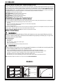
DESCRIPTION OF THE BATTERY CONDITION INDICATORS
The battery condition indicators will give an indication of the state of charge of the batteries. The battery condition monitor will retain the state-of-charge even
if the key has been turned off. The state-of-charge indication is reset to full charge when the batteries have been recharged. It is also possible to choose be-
tween two different low voltage thresholds depending on whether maintenance free or standard batteries are being used (have qualifi ed service engineer
perform this selection). NOTE: The following percentages are based on useable battery capacity not total battery capacity. Therefore, 100% discharge =
80% of total battery capacity for standard wet cell batteries or 70% of total battery capacity for maintenance free batteries.
Green Indicator = full charge down to 50% discharge
Green & Yellow Indicator = 50% discharge down to 75% discharge
Yellow Indicator = 75% discharge down to 90% discharge
Yellow & Red Indicator = 90% discharge down to 95% discharge
Red Indicator = 95% discharge down to 99% discharge
Flashing Red Indicator = 100% discharge - scrub system will automatically shut down
DESCRIPTION OF HOURMETER / STATUS DISPLAY
The 5 character display in the middle of the bottom row of the control panel is primarily used as a display for the hourmeter function. This display is also
used to display the following information depending upon which mode the control is in:
• Error codes*
• Brush pressure adjustment settings for normal and heavy scrub mode (fi xed and adjustable)*
• Display of control system default parameters*
• Recovery tank FULL indicator*
* NOTE: Have a qualifi ed service engineer reference the Service Manual for explanations about the error code descriptions and scrub system control default
parameter changes. A brief description of error codes can be found at the back of this manual.
Emergency Stop Switch / Battery Disconnect (12): This will remove all power from the machine.
INSTALL THE BATTERIES
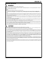
WARNING !
Use extreme caution when working with batteries. Sulfuric acid in batteries can cause severe injury if allowed to contact the
skin or eyes. Explosive hydrogen gas is vented from inside the batteries through openings in the battery caps. This gas can be
ignited by any electrical arc, spark or fl ame.
When Servicing Batteries...
* Remove all jewelry.
* Do not smoke.
* Wear safety glasses, a rubber apron and rubber gloves.
* Work in a well-ventilated area.
* Do not allow tools to touch more than one battery terminal at a time.
CAUTION !
Electrical components in this machine can be severely damaged if the batteries are not installed and connected properly. Batter-
ies should be installed by Nilfi sk-Advance or by a qualifi ed electrician.
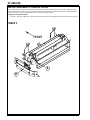
1 Turn the Key Switch (33) off (O) and remove the key. Tip back the recovery tank to expose the battery compartment.
2 Using (2) people and an appropriate lifting strap, carefully lift the batteries into the battery compartment and arrange as shown.
3 See Figure 1. Insert spacers as shown. Install battery cables as shown and tighten the nuts on the battery terminals.
4 Install the battery boots and secure tightly to the battery cables with the supplied tie straps.
5 Install the battery cover and connect the battery pack connector to the machine connector, tip the recovery tank back forward.
NOTE! If total battery weight exceeds 920lbs / 417.31 kg, order and install Isolator Kit PN 56409721.
56409498
12V
12V
12V
56409499
+
+
+
56409498
6V
6V
6V
6V
6V
6V
56409499
56409499
+
+
+
+
+
+
56409499
36V
+
FIGURE 1

FORM NO. 56041587 - Hydro-Retriever
™
3800, 2042 / BR 1100, 1100C, 1100C-XL - 11
ENGLISH / 11
INSTALL THE BRUSHES (DISC SYSTEM)
CAUTION !
Turn the key switch off (O) and remove the key, before changing the brushes, and before opening any access panels.
1 Make sure the Key Switch (33) is off (O). To access the brush mounting plates, remove both the left and right outer side skirt assemblies from the Scrub Brush Deck (13).
Note: The skirts are held in place by two black knobs on each skirt, to separate, loosen knob(s) and pull skirt straight out.
2 To mount the brushes (or pad holders) align the lugs on the brush with the holes on the mounting plate and turn to lock in place (turn outside edge of brush towards
front of machine).
56505791 - Magna Grit 46
56505792 - Dyna Grit 80
56505793 - AgLite Grit 500
56505794 – Prolene
56505795 - ProLite
56505796 - Union Mix
56505797 - MidGrit 240
56505798 - MidLite Grit 180
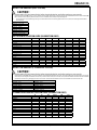
DISC BRUSH APPLICATION GUIDE (SUGGESTION ONLY)
46 80 180 240 500 Union
Application
Grit Grit Grit Grit Grit Prolene Prolite Mix
Stripping:
Concrete
XX
Terrazo
XX
Ceramic/Quarry tile
X
Vinyl tile
X
General Scrubbing:
Concrete
XXXX X
Terrazo
XXXX
Ceramic/Quarry tile
XXXX
Marble
XX
Vinyl tile
XXX
Raised-rubber tile
XX
Polishing:
Raised Disc Tile
X
Marble
X
Vinyl tile
X
INSTALL THE BRUSHES (CYLINDRICAL SYSTEM)
CAUTION !
Turn the key switch off (O) and remove the key, before changing the brushes, and before opening any access panels.
1 Make sure the Key Switch (33) is off (O). To access the brushes, swing both side skirt assemblies open. Note: The skirts are held in place by a large cotter pin on each side,
remove the pins and swing the skirt assemblies out of the way. Loosen the black knobs (one on each side) on top of the idler assemblies and remove the idler assemblies.
Slide the brush into the housing, lift slightly, push and turn until it seats. Re-install the idler assemblies, close the skirt assemblies and secure with cotter pins.
3800C / BR 1100C 2042 / BR 1100C-XL
56410298 - 46 Grit 56409944 - 46 Grit
56410297 - 80 Grit 56409943 - 80 Grit
56410296 - 180 Grit 56409942 - 180 Grit
56410293 – Polypropylene 56409924 – Polypropylene
56410295 - Stiff Nylon 56409941 - Stiff Nylon
56410294 - Soft Nylon 56409940 - Soft Nylon
CYLINDRICAL BRUSH APPLICATION GUIDE (SUGGESTION ONLY)
46 80 180 Polypro- Stiff Soft
Application Grit Grit Grit pylene Nylon Nylon
Stripping:
Concrete X X
Terrazo X X
Ceramic/Quarry tile X
Vinyl tile X
General Scrubbing:
Concrete XXXXX
Terrazo XXXX
Ceramic/Quarry tile XXXX
Marble X X X
Vinyl tile XXXX
Raised-rubber tile X X

12 - FORM NO. 56041587 - Hydro-Retriever
™
3800, 2042 / BR 1100, 1100C, 1100C-XL
12 / ENGLISH
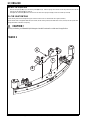
FIGURE 2
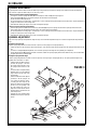
INSTALL THE SQUEEGEE
1 Make sure the Squeegee (18) is up (O) and the Key Switch (33) is off (O). Hold the squeegee tool so that the curved ends point forward, then slide the
squeegee tool onto the Mount (A) (See Figure 2).
2 Hand tighten the Thumb Nuts (B) and then connect the vacuum hose to the Squeegee Tube (C) (vacuum hose should loop to the left).
FILL THE SOLUTION TANK
Read the cleaning chemical label and fi gure the proper amount of chemical to mix for a tank that holds 53 US gallons (200 liters).
Open the Solution Tank Cover (2), then fi ll the tank 1/3 full of water, add the cleaning chemical, then fi ll the tank to 7.62cm (3 inches) from the top of the tank
opening (fi ll to bottom of the wall in tank opening).
CAUTION !
Use only low-foaming, non-fl ammable liquid detergents intended for automatic scrubber machine applications.
A
B
C

FORM NO. 56041587 - Hydro-Retriever
™
3800, 2042 / BR 1100, 1100C, 1100C-XL - 13
ENGLISH / 13
OPERATING THE MACHINE
WARNING !
Be sure you understand the operator controls and their functions.
While on ramps or inclines, avoid sudden stops when loaded. Avoid abrupt sharp turns. Use low speed down hills. Clean only
while ascending (driving up) the ramp.
To Scrub...
Follow the instructions in preparing the machine for use section of this manual.
1 While seated on the machine, adjust the seat and steering wheel to a comfortable operating position using the adjustment controls (45) and (5).
2 Turn the Master Key Switch (33) ON (I). This will display the control panel indicator lights, reference the Battery Condition Indicator (31) and Hour Meter
(32).
3 Release the Parking Brake (6) by fl ipping the set/release lever to the rear while pushing on the Brake Pedal (6). To transport the machine to the work area,
apply even pressure with your foot on the front of the FWD/REV Drive Pedal (8) to go forward or the rear of the pedal for reverse. Vary the pressure on
the foot pedal to obtain the desired speed.
4 Adjust the Solution Flow Control Valve Lever (7) to about 1/4 to 1/3 open position. Note the adjustment can be changed to allow variable solution fl ow
for different types of fl oors to be scrubbed. Example: A rough or absorbent fl oor surface, such as unfi nished concrete, well require more solution than a
smooth fi nished fl oor.
5 Press the Solution Control ON/OFF Touch Pad (30) and hold for 5 seconds. This is done to pre-wet the fl oor. Note: This will help prevent scarring of the
fl oor surface when starting to scrub with dry brushes.
6 Press the Normal Scrub Button (26) for moderate scrub deck pressure or the Heavy Scrub Button (27) for the highest pressure mode. Note refer to the
machine control description section to the have more detailed explanation of this and other control panel functions.
7 When either the Normal Scrub Button (26) or Heavy Scrub Button (27) are selected, the brushes and squeegee automatically are lowered to the fl oor. The
machine’s scrub brushes rotation and solution system fl ow starts when the FWD/REV Drive Pedal (8) is activated. Note: When operating the machine in
reverse, only the brushes will rotate, the solution is automatically shut off to conserve the solution usage.
8 Begin scrubbing by driving the machine forward in a straight line at a normal walking speed and overlap each path by 2-3 inches (50-75 mm). Adjust when
necessary the machine speed and solution fl ow according to the condition of the fl oor.
CAUTION !
To avoid damaging the fl oor, keep the machine moving while the brushes are turning.
9 When scrubbing, check behind the machine occasionally to see that all of the waste water is being picked up. If there is water trailing the machine, you
may be dispensing too much solution, the recovery tank may be full, or the squeegee tool may require adjustment.
10 For extremely dirty fl oors, a one-pass scrubbing operation may not be satisfactory and a “double-scrub” operation may be required. This operation is the
same as a one-pass scrubbing except on the fi rst pass the squeegee is in the up position (press the Vacuum Button (29) to raise the pick up squeegee).
This allows the cleaning solution to remain on the fl oor to work longer. The fi nal pass is made over the same area, with the squeegee lowered to pick up
the accumulated solution.
11 The recovery tank has an automatic fl oat shut-off to prevent solution from entering the vacuum system when the recovery tank is full. When the fl oat
shut-off is activated, the control system will shut down the scrub, vacuum and solution systems. The Vacuum System Fault Indicator (38) will be lit and
the Hour Meter / Status Display (32) will display “FULL”. To clear the display, press the Scrub OFF Button (25). When the fl oat closes, the recovery tank
must be emptied. The machine will not pick up water with the fl oat closed. NOTE: If the control repeatedly gives a full indication when the tank is not full,
the automatic shut-off feature can be disabled, have a qualifi ed service technician perform this function.
12 When the operator wants to stop scrubbing or the recovery tank is full, press the Scrub OFF Button (25) once. This will automatically stop the scrub
brushes and solution fl ow and the scrub deck will raise UP. NOTE: the vacuum/squeegee system will not be turned off when the button is only pressed
once, this is to allow any remaining water to be picked up without turning the vacuum back on. Press the button a second time and the squeegee will raise
and the vacuum will stop after a 10 second delay.
13 Drive the machine to a designated waste water “DISPOSAL SITE” and empty the recovery tank. To empty, pull the Drain Hose (21) from it’s rear storage
area, then remove the plug (hold the end of the hose above the water level in the tank to avoid sudden, uncontrolled fl ow of waste water). Refi ll the solution
tank and continue scrubbing.

14 - FORM NO. 56041587 - Hydro-Retriever
™
3800, 2042 / BR 1100, 1100C, 1100C-XL
14 / ENGLISH
WET VACUUMING
Steps to follow in fi tting the machine with optional attachments for wet vacuuming.
1 Disconnect the recovery hose connection at the recovery tank inlet. Then fi t a 1-1/2 inch (38 mm) Dia. vacuum hose to the recovery inlet.
2 Attach suitable wet pick-up tools to the hose. (An optional Wand Caddy Kit is available from Nilfi sk-Advance).
3 Turn the Master Key Switch (33) ON, next press and hold the Vacuum Button (29) until the indicator light turns green. The vacuum motor will run
continuously until the button is pressed again to turn it OFF. NOTE: If the control repeatedly gives a full indication when the tank is not full, the automatic
shut-off feature can be disabled, have a qualifi ed service technician perform this function.
AFTER USE
1 When fi nished scrubbing, depress the Scrub Off Button (25) twice, this will automatically raise, retract and stop all the machine systems (brush, squeegee,
vacuum & solution). Then drive the machine to a service area for daily maintenance and review of other needed service up keep.
2 To empty the solution tank, remove the Solution Drain Hose (24) from it’s storage clamp. Direct the hose to a designated “DISPOSAL SITE” and remove
the plug. Rinse the tank with clean water.
3 To empty the recovery tank, pull the Recovery Tank Drain Hose (21) from it’s storage area. Direct the hose to a designated “DISPOSAL SITE” and remove
the plug (hold the end of the hose above the water level in the tank to avoid sudden, uncontrolled fl ow of waste water). Rinse the tank with clean water.
4 Remove the brushes or pad holders. Rinse the brushes or pads in warm water and hang up to dry.
5 Remove the squeegee, rinse it with warm water and re-install on mount.
6 Remove the hopper on cylindrical systems and clean thoroughly. Remove from left side of machine by opening skirt and tilting hopper up and away from
housing, then pull out.
7 Check the maintenance schedule below and perform any required maintenance before storage
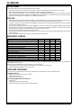
MAINTENANCE SCHEDULE
MAINTENANCE ITEM Daily Weekly Monthly Yearly
Charge Batteries •
Check/Clean Tanks & Hoses •
Check/Clean/Rotate the Brushes/Pads •
Check/Clean the Squeegee •
Check/Clean Vacuum Shut-Off Float •
Check/Clean the vacuum motor foam fi lter •
Clean Hopper on Cylindrical System •
Check Each Battery Cell(s) Water Level •
Inspect Scrub Housing Skirts •
Inspect and clean Solution Filter •
Check Foot/ Parking Brake For Wear & Adjustment •
Clean Solution Trough on Cylindrical System •
Lubrication - Grease Fittings •
* Check Carbon Brushes •
* Have Nilfi sk-Advance check the vacuum motor carbon motor brushes once a year or after 300 operating hours. The brush and drive motor carbon brushes
check every 500 hours or once a year.
NOTE: Refer to the Service Manual for more detail on maintenance and service repairs.
8 Store the machine indoors in a clean dry place. Keep from freezing. Leave the tanks open to air them out.
9 Turn the Master Key Switch (33) OFF (O) and remove the key.
LUBRICATING THE MACHINE
Once a month, pump a small amount of grease into each grease fi tting on the machine until grease seeps out around the bearings.
Grease fi tting locations are:
• Squeegee Caster Wheel Axle & Swivel (2) per Assembly
• Steering Chain Idler Sprocket
• Steering Wheel Shaft Universal joint
Once a month, apply light machine oil to lubricate the:
• Steering Chain
• Squeegee Height Adjustment Caster Hardware
• General Pivot Points For the Squeegee, Brush Linkage and Side Skirts

FORM NO. 56041587 - Hydro-Retriever
™
3800, 2042 / BR 1100, 1100C, 1100C-XL - 15
ENGLISH / 15
CHARGING THE BATTERIES
Charge the batteries each time the machine is used, or whenever the Battery Condition Meter (31) is showing a yellow , red or fl ashing red indicator light(s).
To Charge the Batteries...
1 Drain and tip back the recovery tank to provide proper ventilation.
2 Push the connector from the charger into the Battery Charger Plug (9).
3 Follow the instructions on the battery charger.
4 Check the fl uid level in all battery cells after charging the batteries. Add distilled water, if necessary, to bring the fl uid level up to the bottom of the fi ller
tubes.
WARNING !
Do not fi ll the batteries before charging.
Only charge batteries in a well-ventilated area.
Do not smoke while servicing the batteries.
CAUTION !
To avoid damage to fl oor surfaces, always wipe water and acid from the top of the batteries after charging.
CHECKING THE BATTERY ELECTROLYTE LEVEL
Check the electrolyte level of the batteries at least once a week.
After charging the batteries, remove the vent caps and check the electrolyte level in each battery cell. Use distilled water to fi ll the batteries to the bottom of
the fi ller tube.
Do not over-fi ll the batteries!
CAUTION !
Acid can spill onto the fl oor if the batteries are overfi lled.
Tighten the vent caps. If there is acid on the batteries, wash the tops of the batteries with a solution of baking soda and water (2 tablespoons of baking soda
to 1 quart of water).

16 - FORM NO. 56041587 - Hydro-Retriever
™
3800, 2042 / BR 1100, 1100C, 1100C-XL
16 / ENGLISH
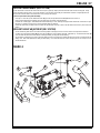
SQUEEGEE MAINTENANCE
If the squeegee leaves narrow streaks or water, the blades may be dirty or damaged. Remove the squeegee, rinse it under warm water and inspect the
blades. Reverse or replace the blades if they are cut, torn, wavy or worn.
To Reverse or Replace the Rear Squeegee Wiping Blade...
1 See Figure 3. Raise the squeegee tool off the fl oor, then unsnap the Center Latch (A) on the squeegee tool.
2 Remove the Wing Nut (B) from each end of the squeegee, then remove the Tension Straps (C).
3 Slip the rear blade off the alignment pins.
4 The squeegee blade has 4 working edges. Turn the blade so a clean, undamaged edge points toward the front of the machine. Replace the blade if all
4 edges are nicked, torn or worn to a large radius.
5 Install the blade, following the steps in reverse order and adjust the squeegee.
To Reverse or Replace the Front Squeegee Blade...
1 Raise the squeegee tool off the fl oor, then loosen the (2) Thumb Nuts (D) on top of the squeegee and remove the squueegee tool from the mount.
2 Remove all the wing nuts that hold the front blade in place, then remove tension strap and blade.
3 The squeegee blade has 4 working edges. Turn the blade so a clean, undamaged edge points toward the front of the machine. Replace the blade if all
4 edges are nicked, torn or worn to a large radius.
4 Install the blade, following the steps in reverse order and adjust the squeegee.
SQUEEGEE ADJUSTMENT
There are two major squeegee tool adjustments, height and angle. The recommended adjustment steps are to set the tool angle fi rst, then adjust the blade
height.
Adjusting the Squeegee Angle
Adjust the squeegee angle whenever a blade is reversed or replaced, or if the squeegee is not wiping the fl oor dry.
1 Park the machine on a fl at, even surface and lower the squeegee. Then drive the machine forward enough to have the squeegee blades fold over to the
rear.
2 Loosen the Lock Wing Nut (G) (hand tightened). This secures the squeegee mount angle from easily vibrating out of adjustment.
3 Turn the Adjustment Knob (H) to tilt the tool forward or backwards, until the rear squeegee wiping blade touches the fl oor evenly across its entire width.
4 Re-tighten by hand the Lock Wing Nut (G).
Adjusting the Squeegee Blade Height
Adjust the squeegee height whenever a blade is reversed or replaced, or if the squeegee is not wiping the fl oor dry. The squeegee blade height is easily
adjustable at the caster wheels. To adjust...
1 Park the machine on a fl at even surface
and lower the squeegee. Then drive
the machine forward enough to have
the squeegee blades fold over to the
rear.
2 Loosen both the lock adjustment Wing
Nuts (E) (need to be hand tightened
only) located on the top of the caster
mount bracket.
3 Rotate the Adjustment Knobs (F) CW
(clockwise) to lift the squeegee and
CCW (counter clockwise) to lower it.
A starting point when replacing the
blades is to adjust the caster mounting
bracket so it is level (parallel) to the
top of the squeegee tool. Note: The
Right and Left caster wheels must be
adjusted equally to maintain level and
even blade pressure.
4 Re-tighten the lock adjustment Wing
Nuts (E) and test for proper squeegee
pick-up.
A
B
C
B
C
D
D
E
E
F
F
G
H
FIGURE 3

FORM NO. 56041587 - Hydro-Retriever
™
3800, 2042 / BR 1100, 1100C, 1100C-XL - 17
ENGLISH / 17
SIDE SKIRT MAINTENANCE (DISC SYSTEM)
The side skirts function is to channel the waste water to the rear pick-up squeegee, helping contain the water with in the machines cleaning path. During
normal use the blades will wear in time. The operator will notice a small amount of water leaking out underneath the side skirts. A height adjustment can
easily be made to lower the blades so that all the water can be pick-up by the squeegee.
To reverse or replace the scrub system side skirt(s) ...
1 See Figure 4. Loosen the (2) side skirt Retainer Knobs (A) (2 per side) and pull the Skirt Assemblies (B) off from the scrub deck.
2 Remove all the hardware that holds both the (short and long) blades and retainers to the skirt housing.
3 Each blade has 4 working edges. Reinstall the blades to the skirt housing so a clean, undamaged edge points inside towards the scrub brushes. Replace
the blades as a set if they are nicked, torn or worn beyond their ability to be adjusted.
4 Reinstall the skirt housing assemblies onto the machine and adjust the blade for proper contact to the fl oor when the brush deck is placed in the scrub
position.
SIDE SKIRT HEIGHT ADJUSTMENT (DISC SYSTEM)
1 The side skirt housing knob retainer screw studs have leveling Adjuster Collars (C), that are to be raised or lowered to compensate for blade wear.
2 To adjust, remove the Skirt Assemblies (B) from the Scrub Deck (D) to access the Adjuster Collars (C). Adjustment Tip: The skirts Retainer Knobs (A)
can be loosened with skirts left on and the Adjuster Collars (C) rotated by reaching under the skirt housing.
3 Turn the Adjuster Collars (C) (Up or Down) to where the blades just fold over enough when scrubbing that all the waste water is contained inside the
skirting. Note: Make small adjustments to obtain good blade wiping. Do not lower the blades too much to where they fold over excessively and cause
unneeded blade wear.
FIGURE 4
A
A
A
A
B
B
C
C
D

18 - FORM NO. 56041587 - Hydro-Retriever
™
3800, 2042 / BR 1100, 1100C, 1100C-XL
18 / ENGLISH
FIGURE 5
SIDE SKIRT MAINTENANCE (CYLINDRICAL SYSTEM)
The side skirts function is to channel the waste water to the rear pick-up squeegee, helping contain the water with in the machines cleaning path. During
normal use the blades will wear in time. The operator will notice a small amount of water leaking out underneath the side skirts. Skirt height adjustment is
automatic on this system. The skirt assemblies should move up and down freely for proper operation.
To replace the scrub system side skirt(s) ...
1 See Figure 5. Remove the (2) (A) Cotter Pins and swing the Skirt Assemblies open. Remove the (B) Screws and Nuts, remove the Skirts and replace.
FRONT
A
B

FORM NO. 56041587 - Hydro-Retriever
™
3800, 2042 / BR 1100, 1100C, 1100C-XL - 19
ENGLISH / 19
GENERAL MACHINE TROUBLESHOOTING
Problem Possible Cause Remedy
Poor water pick-up Worn or torn squeegee blades Reverse or replace
Squeegee out of adjustment Adjust so blades touch fl oor evenly across entire width
Recovery tank full Empty recovery tank
Recovery tank drain hose leak Secure drain hose cap or replace
Recovery tank cover gasket leak Replace gasket / Seat cover properly
Debris caught in squeegee Clean squeegee tool
Vacuum hose clogged Remove debris
Using too much solution Adjust solution control valves
Foam fi lter cover not seated Seat cover properly
Poor scrubbing performance Worn brush or pad Rotate or replace brushes
Wrong brush or pad type Consult Nilfi sk-Advance
Wrong cleaning chemical Consult Nilfi sk-Advance
Moving machine too fast Slow down
Not using enough solution Adjust solution control valves
Inadequate solution fl ow or no solution Solution tank empty Fill solution tank
Solution lines, valves, fi lter or trough clogged Flush lines, trough and clean solution fi lter
Solution control valves not open Adjust solution control valves
Solution solenoid valve Clean or replace valve
Machine does not run Emergency stop switch Rotate the stop switch knob to release
Battery charger port interlock Check for open circuit and replace
Operator seat safety switch Check for open circuit and replace
Main system controller
Check error fault codes (see service manual)
Tripped 10 Amp circuit breaker Check for electrical short circuit & reset
No FWD/REV wheel drive Drive system speed contoller
Check error fault codes (see service manual)
Tripped 80 Amp circuit breaker
Check for drive motor overload
Emergency stop switch tripped Reconnect battery connectors
Vacuum shuts off and display shows
“FULL” when recovery tank is not full
Plugged squeegee hose Clear debris
Vacuuming large amounts of water
at a high travel speed
Slow down or disable auto shut-off feature
(see service manual)
Poor Sweeping Performance
(Cylindrical System)
Hopper Full Empty and clean hopper
Brushes worn Replace brushes
Bristles have taken a set Rotate brushes

20 - FORM NO. 56041587 - Hydro-Retriever
™
3800, 2042 / BR 1100, 1100C, 1100C-XL
20 / ENGLISH
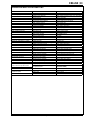
CONTROLLER ERROR CODES
For all error codes: Turn key switch off & then back on. If error persists consult chart below and/or service manual.
Error
Code
Description Possible Cause Corrective Action
1 Control fault Control failure Turn key switch off & back on. If problem persists consult service manual.
2 Critical control fault Control failure Turn key switch off & back on. If problem persists consult service manual.
3 Drive system fault Tripped wheel drive circuit breaker Reset circuit breaker
Throttle not in neutral (HPD fault) Verify that throttle is in neutral before turning key on. Adjust throttle mecha-
nism.
Wheel drive system problem Consult service manual.
4 Scrub deck lift actuator overload Scrub deck obstruction / binding Remove obstruction. Lubricate mechanism.
Defective actuator motor Consult service manual.
5 Scrub deck lift actuator severe overload See error code 4
6 Scrub deck lift actuator circuit open / output fault Bad electrical connection Check all conections to actuator motor.
Defective actuator motor Consult service manual.
Control failure Consult service manual.
7 Scrub motor overload Scrub motor obstruction Remove obstruction. Check to see that motors rotate freely.
Defective scrub motor Consult service manual.
8 Scrub motor severe overload See error code 7
9 Scrub motor circuit open Bad electrical connection Check all conections to scrub motors.
Defective scrub motor(s) Consult service manual.
Control failure Consult service manual.
10 Scrub motor contactor contacts shorted Contactor failure Consult service manual.
11 Not used
12 Scrub motor contactor coil overload Contactor failure Consult service manual.
Coil suppression diode failure Consult service manual.
13 Scrub motor contactor coil severe overload See error code 12
14 Scrub motor contactor coil circuit open / output fault Bad electrical connection Check all connections to scrub motor contactor.
Contactor failure Consult service manual.
Control failure Consult service manual.
15 Not used
16 Not used
17 Scrub motor cable thermistor fault Machine temperature out of range This error will occur if the machine temperature is below 32*F or above 185*F.
This error will not prevent operation of the machine. Scrub pressure may be
affected.
Thermistor failure Consult service manual.
18 Squeegee lift actuator overload Squeegee obstruction / binding Remove obstruction. Lubricate mechanism.
Defective actuator motor Consult service manual.
19 Squeegee lift actuator severe overload See error code 18
20 Squeegee lift actuator circuit open / output fault Bad electrical connection Check all conections to actuator motor.
Defective actuator motor Consult service manual.
Control failure Consult service manual.
21 Not used
22 Not used
23 Not used
La page est en cours de chargement...
La page est en cours de chargement...
La page est en cours de chargement...
La page est en cours de chargement...
La page est en cours de chargement...
La page est en cours de chargement...
La page est en cours de chargement...
La page est en cours de chargement...
La page est en cours de chargement...
La page est en cours de chargement...
La page est en cours de chargement...
La page est en cours de chargement...
-
 1
1
-
 2
2
-
 3
3
-
 4
4
-
 5
5
-
 6
6
-
 7
7
-
 8
8
-
 9
9
-
 10
10
-
 11
11
-
 12
12
-
 13
13
-
 14
14
-
 15
15
-
 16
16
-
 17
17
-
 18
18
-
 19
19
-
 20
20
-
 21
21
-
 22
22
-
 23
23
-
 24
24
-
 25
25
-
 26
26
-
 27
27
-
 28
28
-
 29
29
-
 30
30
-
 31
31
-
 32
32


Nilfisk-Advance BR 1100 Instructions For Use Manual
- Catégorie
- Machine à plancher
- Taper
- Instructions For Use Manual
- Ce manuel convient également à
dans d''autres langues
- italiano: Nilfisk-Advance BR 1100
- English: Nilfisk-Advance BR 1100
- eesti: Nilfisk-Advance BR 1100
Documents connexes
Autres documents
-
Nilfisk ES4000 Le manuel du propriétaire
-
Dolmar MWCS Le manuel du propriétaire
-
Clarke FOCUS II Micro Rider Mode d'emploi
-
Nobles V-WD-16B Mode d'emploi
-
Windsor Chariot 3 CV 86/1 RS Bp Le manuel du propriétaire
-
-
-
-
Windsor Chariot 2 iScrub 20 Deluxe Le manuel du propriétaire
-