Contec FXA3000 Le manuel du propriétaire
- Taper
- Le manuel du propriétaire

IEEE802.11n/a/b/g Wireless LAN
(Access point / Station)
FXA3000-US Setup Guide
CONTEC CO., LTD.
The FXA3000-US is an access point that conforms to IEEE 802.11n/a/b/g wireless networking standards and that
supports a wide range of input power (5 to 30 VDC) and PoE.
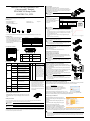
Packing List
-
Main unit (FXA3000-US)...1
-
Setup Guide (English)...1
- Connector cover (Installed in unit)...1
-
Tapping screws...2
- Magnet...2
-
Serial Number Label...1
* You are free to download the manual of this product from the CONTEC’s website (https://www.contec.com/).
Default setting
This product is set up via a network using a Web
browser. Connect this product to the PC with a
LAN cable using the wired LAN connection and
then access the default IP address in a web
browser. This product's default settings are shown
in the table to the right.
Setting Item
Default setting
IP Address
192.168.0.1
Subnet Mask
255.255.255.0
ESSID
LocalGroup
Security
(No input)
User name
admin
Password
pass
Component Locations
(1) Security slot (2) INIT Switch
(3) LAN port (4) DC JACK
(5) Power connector (6)
Power disconnection
prevention hook
LED display INIT Switch
LED name
Status
Indicator
No.
Name
Operation / function
POWER
ON
Indicates that the device is operating.
1 INIT
Used to initialize this product
(reset to factory default
settings). When this switch is
pressed, the POWER,
WLAN, and LAN LEDs
start to flash. If this switch is
released during the period
from when the LEDs start to
flash and until they turn on
(approximately 3 seconds), all
of the access point's settings
will be reset to the factory
default when next started.
Flashing
Indicates that the device is being
started (This device turned on)
OFF
Indicates that the device is power off.
LAN
ON
Indicates that a wired LAN has been
connected.
Flashing
Indicates that the product is
transmitting/receiving data to/from the
connected terminal through wired
LAN.
OFF
Indicates that a wired LAN not logged-
in.
WLAN
ON
Indicates that the device has been
connected.
Flashing
Indicates data is being transmitted to
or received from the device connected
through wireless LAN.
* When initializing the product by turning the INIT
signal on and off, the LEDs will continue flashing
for a short time after the signal is turned off. This
indicates the internal memory files are being
deleted. If the power is turned off while the LEDs
are flashing, the internal memory files may be
damaged and the pro duct may no longer be able to
start properly. Always restart the product after the
LEDs stop flashing.
OFF
Indicates that the device has been no
connected.
POWER/ LAN/
WLAN
Flashing
(simultaneously)
Indicates that firmware has been
reprogrammed. *1
POWER/LAN
Blinking twice /
On
DHCP error
*1 Not include LogFile
Removing the connector cover
While lightly pushing vertically on the center of the connector cover [(1) in the
diagram], slide the entire cover [(2) in the diagram], and remove the connector
cover.
Safety Information
This document provides safety information using the following symbols to prevent accidents resulting in injury or death and the destruction of
equipment and resources. Understand the meanings of these labels to operate the equipment safely.
DANGER indicates an imminently hazardous situation which, if not avoided, will result in death or serious injury.
CAUTION indicates a potentially hazardous situation which, if not avoided, may result in minor or moderate injury or in property damage.
About the speed mark
The link speed shown for the transmission rate in this manual, the setup screens, and elsewhere is the theoretical maximum value based on the wireless
LAN standard and does not represent the actual data transfer rate.
Power Supply
When using the AC adapter (FX-AC053)
Pass the DC plug through the connector cover opening and connect the AC
adapter's DC plug to the product's DC jack. You can prevent the DC plug from
being pulled out by hooking the cord on the power disconnection prevention
hook located on the connector section.
When supplying power via PoE, do not use the power supplied from the power connector or
the AC adapter.
When supplying power from the power
connector
Power can be externally supplied using
the power connector. Use the
components indicated to the right for the
power cable or use equivalent
components.
Function
Power connector: MC1,5/3-ST-3,5(PHOENIX CONTACT),
Cable: AWG28-16(on the condition that the cable length satisfies the power
specifications)
Pin No.
Signal name
Meaning
1 Vi+
Power supply
(5 to 30 VDC ±5%)
2
Vi-
Power supply (GND)
3
FG
Frame ground
-
Carefully manufacture the power cable taking care not to mistake the wiring. In particular, if
the power cable is used with mistaken housing pin numbers, there is a risk of malfunction or
accidents.
-
Input voltage range: 5 to 30 VDC ± 5%. Use a power supp
ly that rises to 4.75 VDC or higher
in the input voltage range within 10 ms. There is a risk of damage to the device or accident if a
power supply outside this range is used.
-
When supplying power with the AC adapter, do not use power supplied from the power
connector.
-
For PoE wire route only in the same building
LAN Port
Connect a LAN cable to this product's LAN port.
-
Ensure that the cable length between this product and a PC or hub is 100 m or shorter.
-
When supplying power via PoE or when using 100BASE-TX, use a Category 5 or better
cable. When using 10BASE-T, use a Category 3 or better cable.
Attaching the security wire
A commercially available security wire can be attached to the security slot
located on the connector section.
Recommended security wires:
-
KOKUYO EAS-L41, Buffalo BSL4DS, SANWA SUPPLY SL-31S
Attaching the connector cover
Attach the connector cover to the product.
Using magnets for installation
Attach the included magnets to the two magnet attachment
locations on the
back of the access point. To attach the magnets, push them in the direction of
the arrow to insert them entirely into the attachment holes.
-
Do not place the magnets near items that are susceptible to magnetic fields.
-
If the produ ct is moved while attached to a steel desk or other object, it may damage the
painted surface.
Using the included screws for installation
Referring to the diagram to the right, drive the two included screws into a
sturdy, vertical wall surface while
leaving around 3 mm of the screws sticking
out from the wall surface.
Hook the attachment holes on the back of the access point to the heads of the
screws to attach it.
Due to the characteristics of wireless networks, the signal will spread in a wider
area
when the access point is installed in a highly-visible location, so we
recommend you install it in a location as high as possible.
Note that the placing the product near metal or concrete walls (including steel
beams) may cause the signal quality to degra
de.
-
The access point cannot be installed on the ceiling using the screws due to the danger of falling.
If a ceiling installation is required, use the optional installation bracket.
-
Caution: If the product's ventilation holes are blocked, the product may malfunction due to a
rise in internal temperature.
Connecting to This Product Using Web Browser
Start up a Web browser and enter the IP address of this product after “http: //” in the address bar. If connecting for the first
time, enter the default IP address. When the default setting IP address is 192.168.0.1, enter as follows.
http://192.168.0.1/
Connecting to this product displays the “Wireless LAN
Manager” login screen/ If the login screen is not disp
layed, the
IP address setting for PC, browser settings, or the URL entered
in the address bar of the browser may be incorrect.
Enter a password on the login screen and then click “Login” to log in.
When connecting for the first time, Default setting is Username=”admin” & Password=”pass” and just click “OK” .
If the login is successful, the following setup screen will be displayed after a little while.
Setup Using Web Browser
Select the desired setting items from the opened menu (1).
Information such as
setting items will be displayed in the right-
hand frame.
For more information about a setting item, please refer to
"help" (2).
Click “Submit” (3) after changing settings on each page to
temporarily save the settings in this product.
The settings become en
abled when the product is restarted
after all the setup procedure is completed and the settings are
stored. Click “Save & Reboot” (4) on the left-hand menu.
There will be no problem if you just save the settings now but reboot the product later when necessary. In this case, saving
the settings does not actually change the settings of the product. Therefore, make sure to reboot the product later
It takes approximately 5 - 10 seconds to save settings (writing to internal flash memory). During that period, the LEDs for POWER, LAN and
WLAN at the front part of the main unit blink simultaneously. Do not reboot or turn off the product until the screen indicates the completion of the
saving process. The setup file data and firmware data may be damaged and the product may not operate properly if it is rebooted or switched off
during the saving process.
SetupGuide
Tapping ScrewsMagnet
x2
FXA3000 Series
Serial Number Label
x2
DANGER
CAUTION
CAUTION
CAUTION
CAUTION
CAUTION
CAU
TION
CAUTION

Specifications
Name
Specification
Unit type Access point / Station / Repeater
Wired LAN
Ethernet standard
IEEE802.3(10BASE-T), IEEE802.3u(100BASE-TX), IEEE802.3af
Port Speed / Communication type /
Number of ports
10/100Mbps/Half Duplex, Full Duplex/ 1
Wireless LAN
Wireless Networking Standard
IEEE802.11n, IEEE802.11a, IEEE802.11b, IEEE802.11g
Channel*1
IEEE802.11n
IEEE802.11a
Access point /
Repeater
5GHz: 9ch(36, 40, 44, 48ch[W52]
149, 153, 157, 161, 165ch [W58] )
Station
5GHz: 21ch(36, 40, 44, 48ch[W52], 52, 56, 60, 64ch [W53],
100, 104, 108, 112, 116, 132, 136, 140ch [W56]
149, 153, 157, 161, 165ch [W58] )
IEEE802.11n, IEEE802.11g,
IEEE802.11b
2.4GHz: 11ch (1 - 11)
IEEE802.11n
Data transmission speed *2
300 - 6.5Mbps[MCS0 - 15, Short/Long GI] (Fixed/Auto)
IEEE802.11a
Data transmission speed *2
54, 48, 36, 24, 18, 12, 9, 6Mbps (Fixed/Auto)
IEEE802.11b
Data transmission speed *2
11, 5.5, 2, 1Mbps (Fixed/Auto)
IEEE802.11g
Data transmission speed *2
54, 48, 36, 24, 18, 12, 9, 6Mbps (Fixed/Auto)
Security
IEEE802.11n
WPA(AES), WPA2(AES), WPA-PSK(AES), WPA2-PSK(AES),
WSL (Combination with mentioned above is possible)
IEEE802.11a/b/g
WEP(Open/ Shared Key /Auto), WPA(AES, TKIP), WPA-PSK(AES,TKIP),
WPA2(AES, TKIP), WPA2-PSK(AES,TKIP), IEEE802.1X(EAP-TLS, PEAP),
WSL (Combination with mentioned above is possible)
Antenna
Chip-antenna x 2 MIMO
External dimension (mm)
Unit only: 136.2(W) x 100.0(D) x 31.0(H) including power cable disconnection
prevention hook
With connecto r cover attached: 170.0(W) x 100.0(D) x 31.0(H)
Weight
220g (Unit only), 250g (With connector cover attached)
*1 Varies depending on the country in which the product is used
*2 These are theoretical values based on their respective wireless LAN standards; they do not indicate actual data transfer rates.
Environmental Specifications
Name
Specification
Input voltage range
5VDC
±
5% (DC Jack), 5 - 30VDC
±
5% (powe r connector), 36 - 57VDC (PoE)
Rating input current
0.83A (5VDC input), 0.15A (30VDC input) (Max.), 0.13A (PoE input 48V)
Operating ambient temperature
0 - 40°C
Operating ambient humidity
10 - 90%RH (No condensation)
Floating dust particles
Not extreme
Corrosive gases
None
Permitted transient power failure
17ms or less (100VAC@25°C)
An automatic reset is performed when low voltage is detected.
Approval standards
FCC, IC, WPC, IMDA, UL/cUL, RoHS Compliant
External Dimensions
External dimensions (Unit only) External dimensions (connector cover attached)
Security Precautions
Wireless LAN uses radio waves instead of LAN cables to send and receive data between a computer and a wireless access point, making it possible to
freely establish a LAN connection within a range of the radio waves. However, radio waves can be received through obstacles, su ch as walls, when
within the range. Therefore, if security settings are not made, the following problems may occur.
Unauthorized viewing of data
An unauthorized third party can intercept the radio waves and view e-mail messages and personal information, such as user ID and password or your
credit card information.
Unauthorized access
An unauthorized third party can access a personal or corporate network and cause the following damage:
- Intercepting personal information and confidential information (information leak)
- Using a false identity to communicate and disclose information illegally (identity theft)
- Changing and transmitting intercepted data (tampering)
- Damaging data and systems by spreading a computer virus (destruction)
The wireless LAN card and wireless access point have security features to counter these problems. Using the security settings of the wireless LAN
equi pment can help p revent these probl ems fro m occur ring. The securit y set tings of t he wire les s LAN e quipment are not co nfigu red at the time of
purchase.
To reduce security problems, configure all security settings of the wireless LAN equipment according to the manual before using the wireless LAN card
and wireless access point. Please be aware that the secu rity settings do not provide complete security protection due to wireless LAN specifications. If
you are unable to configure the security settings yourself, please contact your local authorized dealer. The customer is responsible for configu ring the
security settings and understanding the risks inherent in using the product without the security settings configured.
Notes on Radio Interface
The 2.4 GHz band used by this product covers the operating frequencies of mobile-identification local radio stations (requiring the license), specific low-
power radio stations (requiring no license) and amateur wireless stations (requiring the license) as well as industrial, scientific, and medical equipment
such as microwave ovens.
1. Before using t his product, make sure that there is no mobile-identification local radio station, specific low-pow er radio station and amateur wir eless
statio n operating near the product.
2. If the produ ct should cause radio inter face wi th any mo bil e-identification lo cal radio station or specific low-power radio station, immediately change
the operating frequency to avoid the radio interface.
3. Placing wireless terminals near each other may slows down their data rate because of their mutual interference. You should allow a minimum
clearance of about 1m between stations, 3m between access point and station, and 3m between access points.
4. Co ntact your local retailer or CONTEC if the product has trouble such as recurrent radio interface with mobile-identification local radio stations or
specific lo w-power radio stations
Usage limitation
This product has not been developed or manufactured to be used in systems including the equipment whi ch is directly related to human lives *1 or the
equipment which involves human safet y and may significantly affect the maint enance of pu blic functio ns *2. Therefore, do not use the pro duct for such
purposes. In addition, do not use the produ ct withi n 20cm from a human bo dy o n a regul ar ba sis.
*1: Medical devices such as life-support equipment and devices used in an operating theater.
*2: Main control systems at nuclear power stations, safety maintenance systems at nuclear facilities, other important safety-related systems, operatio n
control systems within group tr ansport systems, air -traffic control systems, etc.
If using the IEEE802.11a standard, ensure that you comply with all relevant laws in the country of use.
Handling Precautions
Do not use the product where it is exposed to flammable or corrosive gas. Doing so may result in an explosion, fire, electric shock, or failure.
- This product co nt ains precision el ectronic elements and mu st not be used in locations subject to physical shock or strong vibration. Otherwise, the
board may malfunction, overheat, or cause a failure.
- Do not use or store this device in high temperature or low temperature surroundings, or do not expose it to extreme temperature changes. Otherwise,
the bo ard may malfu nction, overheat, or cause a f ailure.
- Do not use or store this device where it is exposed to direct sunlight or near stoves or other sources of heat. Otherwise, the board may malfu nctio n,
overheat, or cau se a f ailur e.
- Do not use or store this device near strong magnetic fields or devices emitting electromagnetic radiation. Otherwise, the board may malfunction,
overheat, or cau se a f ailur e.
- If an unusual smell or overheat is noticed, unplug the power cable immediately In the event of an abnormal condition or malfunction, please contact
your ret aile r.
- The specifications of this product are subject to change without notice for enhancement and quality improvement. Even when using the pro du ct
continuously, be sure to read the manual and understand the contents.
- Do not block the ventilation holes by placing objects on the product.
- Do not att empt to modify this device. The manuf acturer will bear no respo nsibil it y whatsoever for the device if it has been modified.
- The product must always be associated with the setup guide.
- Regardless of the foregoing statements, CONTEC is not liable for any damages whatsoever (including damages for loss of business profits) arising
out of the use or inability to use this CONTEC product or the information contained herein.
Federal Communications Commission
FCC Caution: Changes or modifications not expressly approved by the party responsible for compliance could void the user's authority to operate this
equipment.
Note: This equipment has been tested and found to comply with the limits for a Class A digital device, pursuant to part 15 of the FCC Rules. These
limits are designed to provide reasonable protection against harmful interference when the equipment is operated in a commercial environment. This
equipment generates, uses, and can radiate radio frequency energy and, if not installed and used in accordance with the instruction manual, may cause
harmful interference to radio communications. Operation of this equipment in a residential area is likely to cause harmful interference in which case the
user will be required to correct the interference at his own expense.
5.15-5.25GHz band is restricted to indoor operations only.
5.47-5.725GHz band is restricted to indoor operations only.
Co mpliance with FCC requirement 15.407(c)
Data transmission is always initiated by software, which is the passed down through the MAC, through the digital and analog baseband, and finally to
the RF chip. Several special packets are initiated by the MAC. These are the only ways the digital baseband portion will turn on the RF transmitter,
which it then turns off at the end of the packet. Therefore, the transmitter will be on only while one of the aforementioned packets is being transmitted. In
ot her words, this device automatically discontinue transmission in case of either absence of information to transmit or operational failure.
Frequency Tolerance: 20ppm
This transmitter must not be co-located or operated in conjunction with any other antenna or transmitter.
This device complies with Part 15 of FCC Rules and Industry Canada’s license-exempt RSSs. Operation is subject to the following two conditions: (1)
this device may not cause harmful interference, and (2) this device must accept any interference received, including interference that may cause
undesired operation.
This equipment complies with FCC/IC radiation exposure limits set forth for an uncontrolled environment and meets t he F CC radio frequency ( RF)
Exposure Guidelines and RSS-102 of the IC radio frequency (RF) Exposure rules. This equipment should be installed and operated keeping the radiator
at least 20cm or more away from person’s body.
End Product Labeling this transmitter module is authorized only for use in device where the antenna may be installed such that 20 cm may be
maintained between the antenna and users.
The final end product must be labeled in a visible area with the following: “Contains FCC ID: PQRFXE3000-US”.
The grantee's FCC ID can be used only when all FCC compliance requirements are met.
Users in Canada
Contains Transmitter Module IC: 4564A-FXE3000
This device complies with RSS-247 of the Industry Canada Rules. Operatio n is subject to t he following two conditions:
(1) This device may not cause interference; and
(2) This device must accept any interference, including interference that may cause undesired operation of the device.
Contains Transmitter Module IC: 4564A-FXE3000
Cet appareil radio est conforme au CNR-247 d’Industrie Canada. L’utilisation de ce dispositif est autorisée seulement aux deux conditions suivantes :
1) il ne doit pas produire de brouillage, et
2) l’utilisateur du dispositif doit être prêt à accepter tout brouillage radioélectrique reçu, même si ce brouillage est susceptible de compromettre le
fonctionnement du dispositif.
This equipment complies with IC radiation exposure limits set forth for an uncontrolled environment. This equipment should be installed and o perated
with minimum distance 20cm between the radiator and your body.
Cet èquipement est conforme aux limites d’exposition aux rayonnements IC ètablies pour un envirionnement non contrôlè. Cet èquipement doit être
installè et utilisè avec un minimum de 20cm de distance entre la source de rayonnement et votre corps.
5150-5250 MHz band is restricted to indoor operation only.
High-power radars are allocated as primary users (i.e. priority users) of the bands 5250-5350 MHz and 5650-5850 MHz and that these radars could
cause interference and/or damage to LE-LAN devices.
La bande 5150-5250 MHz est restreinte à une utilisation à l’intérieur seulement.
Les radars de haute puissance sont désignés utilisateurs principaux (c.-à-d., qu'ils ont la priorité) pour les bandes 5250-5350 MHz et 5650-5850 MHz, et
ces radars pourraient causer du brouillage et/ou des dommages aux dispositifs LAN-EL.
Compliance with IC requirement RSS-210 A9.4.4
Data transmission is always initiated by software, which is the passed down through the MAC, t hrough the digital and analog baseband, and finally to
the RF chip. Several special packets are initiated by the MAC. These are the only ways the digital baseband portion will turn on the RF transmitter,
which it then turns off at the end of the packet. Therefore, the transmitter will be on only while one of the aforementioned packets is being transmitted. In
other words, this device automatically discontinue transmission in case of either absence of information to transmit or operational failure.
Co nformité à la norme C NR-210 A9.4.4
La transmi ssio n des données est toujours initi ée par le logici el, puis les données sont transmises par l'i ntermédiaire du MAC, par la bande de base
numérique et analogique et, enfin, à la puce RF. Plusieurs paquets spéciaux sont initiés par le MAC. Ce sont les seuls moyens pour qu'une partie de la
bande de base numérique active l'émetteur RF, puis désactive celui-ci à la fin du paquet. En conséquence, l'émetteur reste uniquement activé lors de la
transmission d'un des paquets susmentionnés. En d'autres termes, ce dispositif interrompt automatiquement toute transmission en cas d'absence
d'information à transmettre ou de défaillance.
CONTEC CO.,
LTD.
3-9-31, H imesato , Nishiyo dogaw a-ku, Osaka 555-0025, Japan
October 2018 Edition
http
s://www.contec.com/
NA04035 (LYSM162)
10122018_rev2 [02152017]
No part of this document may be copied or reproduced in any form by any means without prior written consent of CONTEC CO., LTD.
DA
NG
E
R
C
AU
TION
-
 1
1
-
 2
2


Contec FXA3000 Le manuel du propriétaire
- Taper
- Le manuel du propriétaire
dans d''autres langues
- English: Contec FXA3000 Owner's manual
Documents connexes
Autres documents
-
AMX Wave Wireless Accessories and Adapters none Mode d'emploi
-
Panasonic CF-31 Series Operating Instructions Manual
-
Fujitsu Stylistic Q552 Manuel utilisateur
-
Extron WAP 100AC Manuel utilisateur
-
-
Fujitsu Stylistic Q702 Manuel utilisateur
-
Panasonic FZ-G1 Windows 8 Mode d'emploi
-
-
Wistron NeWeb DNUA-P75B Manuel utilisateur
-
 Omron Automotive Electronics Korea OKA-206W Manuel utilisateur
