Kichler Lighting 44050NI Manuel utilisateur
- Taper
- Manuel utilisateur

Date Issued: 09/20/17 IS-44050-CB
We’re here to help 866-558-5706
Hrs: M-F 9am to 5pm EST
CAUTION – RISK OF SHOCK –
Disconnect Power at the main circuit breaker panel or main
fusebox before starting and during the installation.
We’re here to help 866-558-5706
Hrs: M-F 9am to 5pm EST
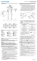
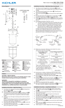
1) Thread Light Assembly[1] to Light Body[2].
2) Place Light Assembly Cup[3] over Light Assembly base and
hold in place using Nut[4] and Nipple[5].
3) Place glass[6] over light socket and hold in place using glass
retainer nut[7].
4) Pass xture wire through stem[8] and attach stem to xture
body[2].
NOTE: Thread locking compound must be applied to all stem
threads as noted with arrow symbol to prevent accidental rota-
tion of xture during cleaning, relamping, etc.
5) Pass xture wire from stem through rst loop[9]. Thread
loop[9] onto end of stem[8].
6) Pass xture wire through second loop[10] and through hole in
canopy[11].
7) Find the appropriate threaded holes on mounting strap[12].
Assemble mounting screws[13] into threaded holes.
8) Attach mounting strap to outlet box[14]. (Screws not provided).
Mounting strap can be adjusted to suit position of xture.
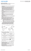
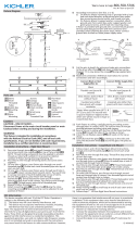
9) Grounding instructions: (See Illus. A or B).
A) On xtures where mounting strap is provided with a
hole and two raised dimples. Wrap ground wire from
outlet box around green ground screw, and thread into
hole.
B) On xtures where a cupped washer is provided. Attach
ground wire from outlet box under cupped washer and
green ground screw, and thread into mounting strap.
If xture is provided with ground wire. Connect xture ground
wire to outlet box ground wire with wire connector. (Not pro-
vided.) After following the above steps. Never connect ground
wire to black or white power supply wires.
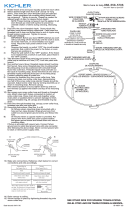
10) Make wire connections (connectors not provided). Reference
chart below for correct connections and wire accordingly.
11) Push xture to ceiling, carefully passing mounting screws[13]
through holes in canopy[11]. NOTE: Be certain wires do not
get pinched between canopy and ceiling.
12) Use knobs[15] and lockwashers[16] to secure canopy. Tighten
to secure.
GREEN GROUND
SCREW
CUPPED
WASHER
OUTLET BOX
GROUND
FIXTURE
GROUND
DIMPLES
WIRE CONNECTOR
OUTLET BOX
GROUND
GREEN GROUND
SCREW
FIXTURE
GROUND
A
B
Connect Black or
Red Supply Wire to:
Connect
White Supply Wire to:
Black White
*Parallel cord (round & smooth) *Parallel cord (square & ridged)
Clear, Brown, Gold or Black
without tracer
Clear, Brown, Gold or Black
with tracer
Insulated wire (other than green)
with copper conductor
Insulated wire (other than green)
with silver conductor
*Note: When parallel wires (SPT I & SPT II)
are used. The neutral wire is square shaped
or ridged and the other wire will be round in
shape or smooth (see illus.)
Neutral Wire
►
►
14
13
12
11
16
15
10
9
8
2
7
6
1
3
4
5

Date Issued: 09/20/17 IS-44050-CB
INSTRUCTIONS
For Assembling and Installing Fixtures in Canada
Pour L’assemblage et L’installation Au Canada
Nous sommes là pour vous aider 866-558-5706
Heures : du lundi au vendredi, de 9h à 17h (heure de l’Est)
ATTENTION – RISQUE DE DÉCHARGES ÉLECTRIQUES -
Couper le courant au niveau du panneau du disjoncteur du
circuit principal ou de la boîte à fusibles principale avant de
procéder à l’installation.
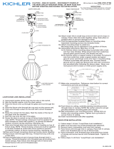
1) Visser le luminaire [1] sur le corps du luminaire [2].
2) Placer la coupelle du luminaire [3] sur la base du luminaire et
la xer à l’aide de l’écrou [4] et du mamelon [5].
3) Placer le verre [6] sur la prise du luminaire et xer à l’aide d’un
écrou de retenue transparent [7].
4) Passer le l du luminaire par la tige [8] et xer la tige au corps
du luminaire [2].
REMARQUE : Appliquer le frein let sur tous les lets de la
tige indiqués par le symbole tels qu’indiqués par le symbole de
la èche pour empêcher la rotation accidentelle du luminaire
pendant le nettoyage, remplacement des ampoules, etc.
5) Passer le l du luminaire de la tige par la première boucle [9].
Visser la boucle [9] dans l’extrémité de la tige [8].
6) Passer le l du luminaire par la deuxième boucle [10] puis par
le trou dans le cache [11].
7) Localiser les trous letés appropriés sur l’étrier de mon-
tage[12]. Serrer les vis de montage [13] dans les trous letés.
8) Fixer l’étrier de montage sur la boîte de sortie. (Vis non
fournies). L’étrier de montage peut être réglé en fonction de la
position du luminaire.
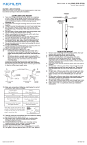
9) Connecter les ls. Se porter au tableau ci-dessous pour faire les
connexions.
10) Pousser le luminaire vers le plafond en passant soigneuse-
ment les vis de montage [13] par les trous dans le cache [11].
REMARQUE : S’assurer que les ls ne se coincent pas entre
le cache et le plafond.
11) Utiliser les boules [15] et les rondelles de blocage [16] pour
sécuriser le cache. Serrer pour xer.
Connecter le fil noir ou
rouge de la boite
Connecter le fil blanc de la boîte
A Noir A Blanc
*Au cordon parallèle (rond et lisse)
*Au cordon parallele (à angles droits el strié)
Au bransparent, doré, marron, ou
noir sans fil distinctif
Au transparent, doré, marron, ou
noir avec un til distinctif
Fil isolé (sauf fil vert) avec
conducteur en cuivre
Fil isolé (sauf fil vert) avec
conducteur en argent
*Remarque: Avec emploi d’un fil paralléle
(SPT I et SPT II). Le fil neutre est á angles
droits ou strié et l’autre fil doit étre rond ou
lisse (Voir le schéma).
Fil Neutre
►
►
14
13
12
11
16
15
10
9
8
2
7
6
1
3
4
5
-
 1
1
-
 2
2


Kichler Lighting 44050NI Manuel utilisateur
- Taper
- Manuel utilisateur
dans d''autres langues
- English: Kichler Lighting 44050NI User manual
Documents connexes
-
 Kichler Lighting 44340WNWLED Manuel utilisateur
-
 Kichler Lighting 42495CLP Manuel utilisateur
-
 Kichler Lighting 43869BK Manuel utilisateur
-
 Kichler Lighting 43953NI Manuel utilisateur
-
 Kichler Lighting 43871OZ Manuel utilisateur
-
 Kichler Lighting 49145DBK Manuel utilisateur
-
 Kichler Lighting 44344WNWLED Manuel utilisateur
-
 Kichler Lighting 49835AZ Manuel utilisateur


