
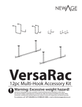
Warning: Excessive weight hazard!
Use two or more people to move, assemble or install overhead rack to avoid back or other injury.
Do not leave children unattended near overhead rack. High risk of injury if installed incorrectly: Follow
instructions carefully and routinely inspect your system to ensure all components are fastened securely.
7FSTB3BD*OTUBMM3FW

2
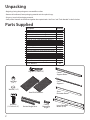
Parts Supplied
Unpacking
• Begin by placing the package on a covered at surface.
• Remove all cardboard, foam packaging material and clear plastic bags.
• Dispose / recycle all packaging materials.
• Verify all the contents in the box and gather the required tools. See “Parts” and “Tools Needed” in the list below.
DescripƟon QuanƟty
1.5” x 1.5” x 6” Ceiling MounƟng Angle 4
1.5” x 1.5” x 18” VerƟcal Angle Posts 4
1.5” x 1.5” x 27” VerƟcal Angle Posts 4
1” x 2.75” x 48” Short Perimeter Beam 2
1” x 2.75” x 51” Long Perimeter Beam A 2
1” x 2.75” x 51” Long Perimeter Beam B 2
47” Cross Supports 6
Center Support Beam 1
Steel Grid Plaƞorms 2
Steel Grid Plaƞorms with Notched Corners 2
Hardware Box 1
1/4” Diameter x 3/4” Long Bolts 24
1/4” N
ylon Lock Nut 24
1/4” Diameter x 3” Long Lag Bolt 8
1/4” Was
hers 56
Vertical Angle Posts
Ceiling
Mounting
Angle
Center
Support Beam
Cross
Supports
Short
Perimeter Beam
Long Perimeter
Beams (A+B)
Steel Grid Platforms
Hex Bolt
(1/4” dia x 3/4”)
Washer (1/4”)
Lock Nut
(1/4”)
Lag Bolt (1/4”dia x 3”)

3
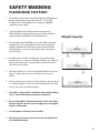
50 lbs. 50 lbs.
500
lbs.
50 lbs.
550
lbs.
600
lbs.
Weight Capacity
SAFETY WARNING
PLEASE READ THIS FIRST
1. All VersaRac units have a rated load capacity of 600 pounds,
evenly distributed, using a minimum of 1.75” lag bolt
anchored into solid wood joists or supports capable of
supporting such a load.
2. Each VersaRac utility hook can hold a maximum of
50lbs, Weight of utility hook storage must be included in
maximum load of 600lbs for the overhead rack.
3. Do not load more than 600lbs on to a VersaRac. Live loads
(people, pets, etc) may weigh less than the rated weight
capacity, however will exert force on the rack beyond its
rated capacity. As such, do not stand, jump or hang from
your VersaRac.
4. VersaRac units must be installed into structurally sound
overhead joists or supports. NewAge Products Inc. makes no
claim to the capacity or strength of the structure to which
the units are mounted.
5. NewAge Products Inc. can not be held liable for structure
failure, or damage or injury resulting from structure
failure.
6. Always inspect the structure of the ceiling to ensure there
is suitable supports. Never install more than one VersaRac
unit on any two overhead supports.
7. VersaRac is designed for installation into wooden ceiling
joists. Do not attempt mounting to steel beams.
8. Ensure all weight is distributed evenly on the rack. Place
heavier objects near the vertical angle posts, and lighter
objects in the center.
9. Do not jump or climb on your VersaRac.
11. Routinely inspect your system to ensure all components
are fastened securely.

4
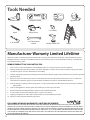
Tools Needed
Magnetic Leveler
Tape Measure
7/16” socket
Cordless Power Drill
Stud Finder
Pencil
7/16” Socket driver
wrench
Ladder
Rubber Mallet
Safety Glasses
3/16” Drill Bit
Manufacturer Warranty Limited Lifetime
1. Service calls to correct the installation of any NewAge products or to instruct you how to use or install them.
2. Damage resulting from improper handling, or products damaged by accident, misuse, abuse, re, ood, improper installation,
acts of God, neglect, corrosion, modication or mishandling.
3. Products damaged by improperly loading beyond the specied maximum weight capacity outlined in the instructions provided
with the product.
4. Repairs or replacement when your product is used in other than normal, single-family household use, such as a commercial
environment, or handled in anyway inconsistent with the installation instructions included with the product.
5. Cosmetic damage, including scratches, dings, dents or cracks in paint that do not aect the structural or functional capability
of the product.
6. Surfaces damaged due to chemical interaction resulting in corrosion of paint or metal.
7. Replacement parts for NewAge products outside Canada and the United States.
8. Loss of product contents due to theft, re, ood, accident or acts of God.
9. Shipping or freight fees to deliver replacement products or to return defective products.
10. Any labor costs during the limited warranty period.
When this product is installed, operated and maintained according to the instructions attached to or furnished with the product,
NewAge Products Inc. will replace the defective product or parts if the part fails as a result of defective materials or workmanship
for the Lifetime of the product.
NEWAGE PRODUCTS INC. WILL NOT PAY FOR:
IMPLIED WARRANTIES, INCLUDING TO THE EXTENT APPLICABLE WARRANTIES OF MERCHANTABILITY OR FITNESS FOR A PARTICULAR
PURPOSE, ARE EXCLUDED TO THE EXTENT LEGALLY PERMISSIBLE. ANY IMPLIED WARRANTIES THAT MAY BE IMPOSED BY LAW ARE LIMITED
TO ONE YEAR, OR THE SHORTEST PERIOD ALLOWED BY LAW. SOME STATES AND PROVINCES DO NOT ALLOW LIMITATIONS OR EXCLUSIONS
ON HOW LONG AN IMPLIED WARRANTY OF MERCHANTABILITY OR FITNESS LASTS, SO THE ABOVE LIMITATIONS OR EXCLUSIONS MAY NOT
APPLY TO YOU. THIS WARRANTY GIVES YOU SPECIFIC LEGAL RIGHTS, AND YOU MAY ALSO HAVE OTHER RIGHTS WHICH VARY FROM STATE
TO STATE OR PROVINCE TO PROVINCE
DISCLAIMER OF IMPLIED WARRANTIES; LIMITATION OF REMEDIES

5
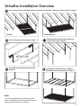
VersaRac Installation Overview
Install ceiling mounting angles. (Page 7 - 8)
48, 72 or 96”
B
Determine desired VersaRac height and
install vertical posts (Page 9)
C
Assemble and install perimeter beams
(Page 10)
D
Install center beam and cross supports
followed by wire grid platforms. (Page 11)
E
Plan your VersaRac installation location, determine orientation and verify spacing of joists. (Page 6)
PerpendicularParallel
A
Note:
It is recommended that you read through the
entire installation instruction manual rst before
beginning your VersaRac installation.

6
72” / 96”
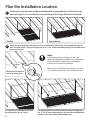
Check the spacing of your ceiling joists to ensure that they will work for the size and direction of
your VersaRac Install. If the spacing of your joists is 24” there should be ceiling joists located in the
necessary position.
1
Determine if your VersaRac will be installed parallel or perpendicular to the direction of
your ceiling joists. Use a stud nder to locate the joists if ceiling is nished with drywall.
Plan the Installation Location
PerpendicularParallel
48”
Parallel Perpendicular
For a perpendicular installation ensure that the ceiling joists
are 72” or 96” apart depending on the VersaRac conguration
that best suits your preferred assembled size.
For a parallel installation ensure that
the ceiling joists are 48” apart.
Measure from center to
center of ceiling joists
2
Note:
If the spacing of your ceiling joists does not
match the preferred assembled size and direction
of your VersaRac installation you will need to
install a joist in the correct position.
Please refer to “Installing a Joist Hanger” on page
12 to install a ceiling joist in the desired position.

7
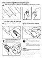
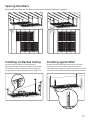
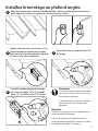
Locate and mark the center of ceiling joist. Use a stud nder to locate the joists if ceiling is
nished with drywall.
Align center of keyhole slots on the ceiling
mounting angle with the centerline of the
ceiling joist and mark the holes on both
ends.
Drill pilot holes using a 3/16” drill bit.
Install ceiling mounting angle into joist
using two 1/4” x 3” lag bolts, two 1/4”
washers and a 7/16” socket.
Note:
Make sure the lag bolts are tight against
the joist but DO NOT over-tighten the
lag bolts.
If lag bolts are over-tightened, the bolt
could snap or the hole may be stripped.
4
6
Install Ceiling Mounting Angles
3
5
Warning:
VersaRac is designed for installation into wooden
ceiling joists only.
If the construction of your ceiling is using
engineered ceiling joists, please refer to “Fastening
to Engineered Joists” on page 14.

8
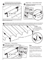
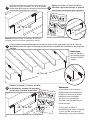
48, 72 or 96”
Depending on the VersaRac size and orientation as
determined on page 6, measure 48, 72 or 96” from
the installed ceiling mounting angle to determine the
location of the second ceiling mounting angles.
48, 72 or 96”
48, 72 or 96”
7
9
Depending on the VersaRac size and orientation that best suits your application, measure 48, 72 or 96” from
the installed ceiling mounting angles to determine the location of the remaining ceiling mounting angles
Note: Ceiling Mounting Angles must be measured from
the same end of the bracket.
Repeat steps 1 - 4 to install the second
ceiling mounting bracket in the same
orientation as the rst.
8
48, 72 or 96”
1
Locate and mark the center of ceiling joist. Use a stud nder to locate the joists if ceiling
is nished with drywall.
Align center of keyhole slots on the ceiling
mounting angle with the centerline of
the ceiling joist and mark two holes
leaving one
Drill pilot holes using a 3/16” drill bit.
Install ceiling mounting angle into joist
using two 1/4” x 3” lag bolts, two 1/4”
washers and a 7/16” socket.
Note:
Make sure the lag bolts are tight
against the joist but DO NOT
over-tighten the lag bolts.
If lag bolts are over-tightened,
the bolt could snap or the hole
may be stripped.
2
3
4
Note:
Measure ceiling
mounting angles
from the same side
of bracket.
48, 72 or 96”
Repeat steps 1 - 4 to install the
remaining ceiling mounting brackets in
the same orientation.
10
1
Locate and mark the center of ceiling joist. Use a stud nder to locate the joists if ceiling
is nished with drywall.
Align center of keyhole slots on the ceiling
mounting angle with the centerline of
the ceiling joist and mark two holes
leaving one
Drill pilot holes using a 3/16” drill bit.
Install ceiling mounting angle into joist
using two 1/4” x 3” lag bolts, two 1/4”
washers and a 7/16” socket.
Note:
Make sure the lag bolts are tight
against the joist but DO NOT
over-tighten the lag bolts.
If lag bolts are over-tightened,
the bolt could snap or the hole
may be stripped.
2
3
4
Note:
If the spacing of your ceiling joists
does not match the preferred
assembled size and direction of
your VersaRac installation you will
need to install a joist in the correct
position.
Please refer to “Installing a Joist
Hanger” on page 12 to install a
ceiling joist in the desired position.

9
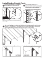
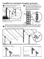
Determine desired height of VersaRac from
Ceiling to bottom of the overhead rack.
18”
or
27- 42“
If desired height is greater than 18”,
Bolt an 18” vertical angle post to a 27” post with
two 1/4” x 3/4” bolts, two 1/4” lock nuts and four
1/4” washers. Use one bolt on each side of the
post with keyholes in the same direction.
Repeat for the remaining vertical angle posts.
Note: Storage space will be 3” shorter than the full height
of the VersaRac
3”
Bolt vertical angle posts to ceiling angle brackets with the large end of the keyslot on top
using a 1/4” x 3/4” bolt, a 1/4” lock nut and two 1/4” washers for each post. Vertical angle
posts should be orientated so that they form the corners of the VersaRac.
Note:
Vertical Angle Post on the left will be installed on opposite sides of the ceiling angle brackets from the right.
Left Side Right Side
Install Vertical Angle Posts
Minimum
3”
Overlap
11 12
13

10
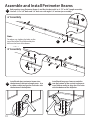
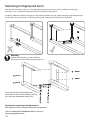
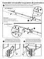
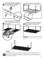
Install both short perimeter beams into
the bottom of the vertical angle posts. Use
a rubber mallet to align the rivet nubs with
the bottom of the keyholes.
Install both long cross beam assemblies
into the bottom of the vertical angle posts.
use a Rubber mallet to align the rivet nubs
with the bottom of the keyholes.
Bolt together Long Perimeter Beams A and B at the desired 6’ or 8’ (72” or 96”) length assembly.
Use four 1/4” x 3/4” bolts and 1/4” lock nuts with eight 1/4” washers per assembly.
8’ Assembly
Note:
To reduce sag, tighten the bolts on the
top of the beams rst followed by the
bolts on the front of the beams.
Assemble and Install Perimeter Beams
6’ Assembly
14
15 16
1
st
1
st
2
nd
2
nd

11
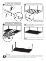
Bolt the Center Support into the holes found
in the middle of the 6’ or 8’ assembly. Use two
1/4” x 3/4” bolts and 1/4” lock nuts with four
1/4” washers per side.
17
Place the cross supports into the slots on
the top of the long cross beam assemblies.
18
Note:
If installing 6’ VersaRac you will
have two cross supports left over.
Place both wire grids with notched corners on
the ends of the VersaRac. Notched corners should
provide clearance for the Vertical Angle Supports.
19
Place one wire grid between the previously
installed grids if installing a 6’ VersaRac, or 2
if it is an 8’ VersaRac.
20
Note:
If installing 6’ VersaRac you will have one grid section left over.
Warning:
Periodically (at least quarterly) inspect your VersaRac unit to ensure beams are seated properly and
brackets are rmly connected to the overhead supports. If there is no sucient structure, remove
the overhead and install the ceiling mounting angles into proper ceiling support.

12
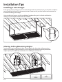
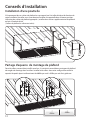
Installing a Joist Hanger
If the spacing of your ceiling joists do not match the desired size and direction of your VersaRac installation
you will need to install a joist in the correct position. Please consult your local professional contractor for
assistance installing a joist hanger.
Using suitable joist hangers, install two additional wooden ceiling joists in the desired location.
(ceiling joist, joist hanger and hardware not included)
48” / 72” / 96”
Installation Tips
Sharing Ceiling Mounting Angles
Two VersaRac’s can be installed with their 4’ ends together by sharing the ceiling mounting
angles in the middle. Installing VersaRac’s in this conguration reduces the evenly distributed
weight capacity from 600lbs per overhead rack to 450lbs per overhead rack.
450 lbs.
450 lbs.

13
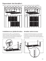
Spacing VersaRac’s
Never install more than one VersaRac unit on any two overhead ceiling joist supports.
Installing on Slanted Ceiling
VersaRac can be installed on a slanted ceiling by
adjusting the length of the vertical angle post assemblies.
The VersaRac must be installed with a horizontally level
storage platform, and vertically level vertical angle posts.
Installing against Wall
VersaRac can be installed against the wall on one end by
bracing a 2in by 4in wood spacer against the wall and
bolting the vertical angle irons to the wood spacer. 2in by 4in
wood spacer and additional hardware required not included.

14
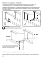
Fastening to Engineered Joists
If the construction of your ceiling is using engineered ceiling joists you must install an additional ceiling joist
(minimum 2” x 8”) perpendicular between two of the engineered ceiling joists.
Install four additional wooden ceiling joists in the required locations for your ceiling mounting angles depending on
the VersaRac size and orientation as determined on page 6 (ceiling joist and hardware not included)
Warning:
Engineered ceiling joists are not suitable for
directly fastening the ceiling mounting angles to.
Please consult your local professional
contractor for assistance installing a ceiling
joist into your engineered ceiling joists
Thank you for purchasing a NewAge Product!
Please give us a call or visit online if you have any questions.
Call 1.877.306.8930; for UK 0800.031.4069; e-mail us at
info@newageproducts.com

Avertissement:Risque de poids excessif!
Utilisez deux ou plusieurs personnes pour déplacer , assembler ou installer porte-bagages pour éviter le dos
ou d'autres blessures .
Ne pas laisser les enfants sans surveillance à proximité de porte-bagages . Risque élevé de blessure si mal
installé : Suivez les instructions soigneusement et régulièrement inspecter votre système pour assurer que
tous les composants sont bien xées .
Réglable étagère de rangement

2
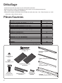
Pièces fournies
Déballage
• Commencez par placer le paquet sur une surface plane recouverte.
• Retirez tout carton, matériau d’emballage en mousse et des sacs en plastique transparent .
• Jeter / recycler tous les matériaux d’emballage .
• Vériez tout le contenu de la boîte et de rassembler les outils nécessaires . Voir « Pièces fournies» et « Outils
nécessaires » dans la liste ci-dessous.
Description 4’ X 6’ / 4’ X 8’
Équerre de montage de plafond1.5” x 1.5” x 6” 4
Montants d’angle verticaux1.5” x 1.5” x 18” 4
Montants d’angle verticaux1.5” x 1.5” x 27” 4
Court Périmètre Poutre 1” x 2.75” x 48” 2
Longue Périmètre Poutre 1” x 2.75” x 51” (A) 2
Longue Périmètre Poutre 1” x 2.75” x 51” (B) 2
Support de grille d'acier 47” 6
Poutre de support centrale 1
Plateformes en treillis métallique 4
Boulon de 1/4” x 3/4” de longueur 24
Contre-écrou en nylon de 1/4” 24
Tire-fond de 1/4” de diamètre et 3”de longueur 8
Rondelles 56
Instructions d’installation, schémas de montage et garantie 1
Montants d’angle
verticaux
Équerre de
montage de
plafond
Poutre de support
centrale
Support de grille d’acier
47”
Court
Périmètre Poutre
Plateformes en treillis
métallique
Boulons
Hexagonale
(1/4” dia x 3/4”)
Rondelles (1/4”)
Contre-écrou
(1/4”)
Boulons de longeurt
(1/4”dia x 3”)
Longue
Périmètre Poutre (A+B)

3
50 lbs. 50 lbs.
500
lbs.
50 lbs.
550
lbs.
600
lbs.
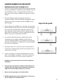
Capacité de poids
AVERTISSEMENT DE SÉCURITÉ
PRIÈRE DE LIRE TOUT D’ABORD CECI
1. Toutes les unités VersaRac disposent d’une capacité nominale
de charge de 600 libres, distribuée de manière égale, utilisant
un tire-fond d’au moins 1,75 po ancré dans des solives en
bois massif ou des supports capables de supporter une telle
charge.
2. Chaque utilitaire crochet VersaRac peut contenir un
maximum de 50lbs , Poids de l’utilité de stockage de crochet
doit être inclus dans la charge maximale de 600lbs pour le
porte-bagages .
3. Ne pas charger plus de 600 lb sur un VersaRac. Il est possible
que les charges vivantes (personnes, animaux de compagnie,
etc.) soient moins lourdes que la capacité nominale, mais
elles exerceront tout de même une force supérieure à celle
admissible. Par conséquent, il n’est pas approprié de se tenir
debout, sauter ou se suspendre au VersaRac.
4. Les unités VersaRac doivent être installées à des solives
suspendues ou des supports adéquats du point de vue
structurel. NewAge Products Inc. ne donne aucune garantie
concernant la capacité ou la solidité de la structure à laquelle
les unités sont assemblées.
5. NewAge Products Inc. ne peut être tenu responsable de
la rupture, ou de dommages ou blessures entraînés par la
rupture de la structure.
6. Toujours inspecter la structure du plafond pour assurer
qu’il y a des supports appropriés . Ne jamais installer plus
d’une unité VersaRac sur les deux supports généraux.
7. VersaRac n’est pas conçu pour les maisons à charpente
métallique.
8. S’assurer que tout le poids est réparti uniformément sur
la grille. Placez les objets les plus lourds près des postes
angle vertical et des objets légers dans le centre.
9. Ne pas sauter ou grimper sur votre VersaRac.
11. Vériez régulièrement votre système pour s’assurer que
tous les composants sont bien xées.

4
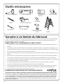
Outils nécessaires
12” vérin magnétique
Ruban à mesurer
7/16” Douille
Perceuse mecanique
sans ls
Localisateur de
montants
Crayon
7/16” cle a douilles
Échelle
Mallot en caoutchouc
Lunettes de protection
3/16” Foret
Garantie à vie limitée du fabricant
1. Les appels de service pour corriger l’installation de tout produit NewAge ou pour vous montrer comment les utiliser ou les
installer.
2. Les dommages causés par une manutention ou une expédition inadéquate du produit, ou des produits endommagés par un
accident, une mauvaise utilisation, un abus, un incendie, une inondation, une installation inadéquate, un cas fortuit, une négli-
gence, la corrosion, une modication ou une mauvaise manipulation.
3. Les produits endommagés en raison d’une charge supérieure au poids maximum précisé dans les instructions fournies avec le
produit.
4. Les réparations ou le remplacement lorsque votre produit est utilisé pour un autre usage que celui d’un ménage unifamilial
normal, comme un milieu commercial ou d’une façon non conforme aux directives d’installation incluses avec le produit.
5. Les dommages cosmétiques, y compris les éraures, les marques, les entailles ou les ssures dans la peinture qui n’aectent pas
la capacité fonctionnelle ou structurelle du produit.
6. Les surfaces endommagées en raison d’une interaction chimique entraînant la corrosion de la peinture ou du métal.
7. Les pièces de rechange pour des produits NewAge à l’extérieur du Canada et des États-Unis.
8. La perte des produits y étant contenus en raison d’un vol, d’un incendie, d’une inondation, d’un accident ou de cas fortuits.
9. Les frais d’expédition ou de transport pour livrer les produits de rechange ou pour retourner des produits défectueux.
10. Tout coût de main-d’oeuvre pendant la période de garantie limitée.
Lorsque ce produit est installé, utilisé et entretenu conformément aux instructions ci-jointes ou fournies avec le produit, NewAge
Products Inc. remplacera les pièces ou le produit défectueux advenant que ceux-ci découlent d’un défaut de matériel ou de
fabrication pendant la durée de vie du produit.
NEWAGE PRODUCTS INC. N’ASSUMERA PAS LES COÛTS SUIVANTS :
LES GARANTIES IMPLICITES, Y COMPRIS LES GARANTIES APPLICABLES DE QUALITÉ MARCHANDE OU DE CONVENANCE PRÉCISE, SONT
EXCLUES DANS LA LIMITE OÙ LA LOI LE PERMET. TOUTE GARANTIE IMPLICITE QUI POURRAIT ÊTRE IMPOSÉE PAR LA LOI DOIT SE LIMITER
À UN AN, OU À LA PÉRIODE LA PLUS COURTE PERMISE PAR LA LOI. CERTAINS ÉTATS AINSI QUE CERTAINES PROVINCES NE PERMETTENT
PAS LES LIMITATIONS OU LES EXCLUSIONS SUR LA DURÉE D’UNE GARANTIE IMPLICITE DE QUALITÉ MARCHANDE OU DE CONVENANCE
PRÉCISE. PAR CONSÉQUENT, IL EST POSSIBLE QUE LES LIMITATIONS OU EXCLUSIONS PRÉCITÉES NE S’APPLIQUENT PAS À VOUS. CETTE
GARANTIE VOUS DONNE DES DROITS LÉGAUX PARTICULIERS ET VOUS POURRIEZ ÉGALEMENT DISPOSER D’AUTRES DROITS VARIANT
SELON L’ÉTAT OU LA PROVINCE.
EXONÉRATION DE GARANTIES IMPLICITES; LIMITATION DE RECOURS

5
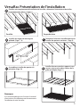
VersaRac Présentation de l’installation
Installer des angles de montage au
plafond. (Page 7 - 8)
48, 72 or 96”
B
Déterminer la hauteur VersaRack désirée et
installer des poteaux verticaux. (Page 9)
C
Assembler et installer des poutres de
périmètre.(Page 10)
D
Installer faisceau central et supports trans-
versaux suivis par les plates-formes de la
grille métallique.(Page 11)
E
Planiez votre emplacement d’installation de VersaRac , déterminer l’orientation et de vérier
l’espacement des solives . ( Page 6 )
Perpendiculaire
Parallèle
A
Remarque:
Il est recommandé que vous lisez tout le manuel
d’instructions d’installation avant de commencer
l’installation de votre VersaRac .

6
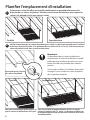
72” / 96”
Vériez l’espacement de vos solives de plafond pour veiller à ce qu’ils vont travailler pour la taille et
la direction de votre VersaRac. Si l’espacement de vos solives est de 12 “ou 24 “ il devrait y avoir des
solives de plafond situés dans la position nécessaire.
1
Déterminez si votre VersaRac sera installé parallèlement ou perpendiculairement à la
direction de vos solives de plafond . Utilisez un localisateur de montants pour repérer les
solives si le plafond est ni avec cloisons sèches .
Planier l’emplacement d’installation
PerpendiculaireParallèle
48”
Pour une installation perpendiculaire veiller à ce que les
solives de plafond sont 72 “ ou 96 “ en fonction en dehors de
la conguration VersaRac qui convient le mieux à votre taille
assemblé préféré .
Pour une installation parallèle veiller à ce
que les solives de plafond sont 48 “à part .
Mesure de centre à centre
des solives de plafond
2
Remarque:
Si l’espacement de vos solives de plafond ne
correspond pas à la taille et la direction assemblé
préféré de votre installation VersaRac vous aurez
besoin d’installer une poutrelle dans la bonne
position .
S’il vous plaît se référer à “Installation d’une solive “
à la page 12 pour installer une solive du plafond
dans la position souhaitée .
Perpendiculaire
Parallèle
La page est en cours de chargement...
La page est en cours de chargement...
La page est en cours de chargement...
La page est en cours de chargement...
La page est en cours de chargement...
La page est en cours de chargement...
La page est en cours de chargement...
La page est en cours de chargement...
-
 1
1
-
 2
2
-
 3
3
-
 4
4
-
 5
5
-
 6
6
-
 7
7
-
 8
8
-
 9
9
-
 10
10
-
 11
11
-
 12
12
-
 13
13
-
 14
14
-
 15
15
-
 16
16
-
 17
17
-
 18
18
-
 19
19
-
 20
20
-
 21
21
-
 22
22
-
 23
23
-
 24
24
-
 25
25
-
 26
26
-
 27
27
-
 28
28


NewAge Products 41200 Mode d'emploi
- Taper
- Mode d'emploi
dans d''autres langues
Documents connexes
-
 NewAge Products 41200 Manuel utilisateur
-
NewAge Products Inc. 40131 Manuel utilisateur
-
 NewAge Products 40132 Manuel utilisateur
-
 NewAge Products 31091 Mode d'emploi
-
NewAge Products 50827 Manuel utilisateur
-
NewAge Products 54233 Manuel utilisateur
-
 NewAge Products Inc. 40400 Manuel utilisateur
-
 NewAge Products 40403 Mode d'emploi


