Kichler Lighting 43854CH Manuel utilisateur
- Taper
- Manuel utilisateur

CAUTION – RISK OF SHOCK – Disconnect Power at the main
circuit breaker panel or main fuse box before starting and
during the installation.
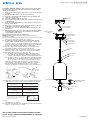
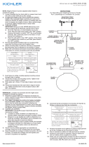
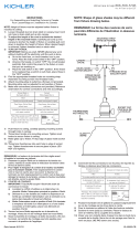
1) Insert steel washer all the way into the slot on the slotted
coupler.
2) Slip the flexible washer onto the steel washer.
3) Pass the cord up through the glass and out through the
small hole at the top.
4) Pass the cord through the top cup.
5) Loosen threaded stud on strain relief. Insert cord into hole
in strain relief.
6) Slide the strain relief and top cup down the cord close to
the top of the glass.
7) Raise the socket into the glass. Rest the inside of the top
of the glass onto the inserted washers.
8) Place the top cup over the hexnut that is threaded to the
short pipe.
9) Thread the strain relief onto the short threaded pipe that is
protruding through the top cup. Tighten to secure the
socket fixture to the glass.
10) Tighten threaded stud on strain relief.
NOTE: Height of fixture must be adjusted before fixture is
mounted to ceiling.
11) Loosen threaded stud on strain relief on canopy. Insert cord
into hole in strain relief and up into canopy.
12) To adjust the length of the cord to achieve the desired
height of the mounted fixture: Carefully pull cord up into
canopy to shorten the height of fixture or carefully pull cord
down to lengthen the height of fixture. When desired height
is achieved, tighten threaded stud on strain relief.
13) Find the appropriate threaded holes on mounting strap.
Assemble mounting screws into threaded holes.
14) Attach mounting strap to outlet box. (Screws not provided).
Mounting strap can be adjusted to suit position of fixture.
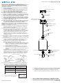
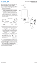
15) Grounding instructions: (See Illus. A or B).
A) On fixtures where mounting strap is provided with a
hole and two raised dimples. Wrap ground wire from
outlet box around green ground screw, and thread into hole.
B) On fixtures where a cupped washer is provided. Attach
ground wire from outlet box under cupped washer and
green ground screw, and thread into mounting strap.
If fixture is provided with ground wire. Connect fixture
ground wire to outlet box ground wire with wire connector.
(Not provided.) After following the above steps. Never
connect ground wire to black or white power supply wires.
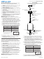
16) Make wire connections (connectors not provided.) Reference
chart below for correct connections and wire accordingly.
17) Push fixture to ceiling, carefully passing mounting screws
through holes in canopy.
18) Thread lock-up knobs onto mounting screws. Tighten knurl
knobs to secure fixture to ceiling.
GREEN GROUND
SCREW
CUPPED
WASHER
OUTLET BOX
GROUND
FIXTURE
GROUND
DIMPLES
WIRE CONNECTOR
OUTLET BOX
GROUND
GREEN GROUND
SCREW
FIXTURE
GROUND
A
B
Connect Black or
Red Supply Wire to:
Connect
White Supply Wire to:
Black White
*Parallel cord (round & smooth) *Parallel cord (square & ridged)
Clear, Brown, Gold or Black
without tracer
Clear, Brown, Gold or Black
with tracer
Insulated wire (other than green)
with copper conductor
Insulated wire (other than green)
with silver conductor
*Note: When parallel wires (SPT I & SPT II)
are used. The neutral wire is square shaped
or ridged and the other wire will be round in
shape or smooth (see illus.)
Neutral Wire
Date Issued: 12/19/16
IS-43854-US
SEE OTHER SIDE FOR SPANISH TRANSLATIONS.
VEA EL OTRO LADO DE TRADUCCIONES AL ESPAÑOL.
We’re here to help 866-558-5706
Hrs: M-F 9am to 5pm EST
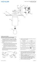
UL KNOT REQUIRED
AFTER ASSEMBLY
MOUNTING SCREWS
OUTLET BOX
WIRE
CONNECTORS
STRAP MOUNTING
SCREWS
MOUNTING STRAP
CANOPY
LOCK-UP KNOBS
LOCKWASHERS
STEEL WASHER
NEOPRENE WASHER
SLOTTED COUPLER
SWIVEL
SOCKET
SHORT THREADED PIPE
TOP CUP
STRAIN RELIEF
CORD
STRAIN RELIEF
GLASS

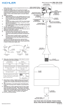
17) Empuje el artefacto hacia el techo, pasando cuidadosamente
los tornillos de montaje a través de los orificios en el escudete.
18) Atornille las perillas estriadas en los perillas de sujeción.
Ajuste las perillas estriadas para fijar el artefacto en el techo.
PRECAUCIÓN – RIESGO DE DESCARGA ELÉCTRICA – Desco-
necte la electricidad en el panel principal del interruptor
automático o caja principal de fusibles antes de comenzar y
durante la instalación.
1) Inserte totalmente la arandela de acero en la ranura del
acoplador ranurado.
2) Deslice la arandela flexible sobre la arandela de acero.
3) Pase el cordón hacia arriba a través del vidrio, y hacia
afuera a través del pequeño agujero arriba.
4) Pase el cordón a través de la taza superior.
5) Afloje el espárrago roscado en el aliviador de tensión.
Inserte el cordón en el agujero en el aliviador de tensión.
6) Deslice el aliviador de tensión y la taza superior a lo largo
del cordón cerca de la parte superior del vidrio.
7) Suba el portalámparas hacia el vidrio. Coloque el interior
de la parte superior del vidrio en las arandelas insertadas.
8) Coloque la taza superior sobre la tuerca hexagonal que
está enroscada al tubo corto.
9) Enrosque el aliviador de tensión en el tubo roscado corto
que sobresale a través de la taza superior. Apriete para
asegurar el portalámparas del artefacto al vidrio.
10) Apriete el espárrago roscado en el aliviador de tensión.
NOTA: La altura del artefacto debe ser ajustada antes de que el
artefacto sea montado en el techo.
11) Afloje el espárrago roscado en el alivio de la tensión en el
escudete. Inserte el cordón en el agujero en el alivio de
tensión y hasta en el escudete.
12) Para ajustar la longitud del cordón para lograr la altura
deseada del artefacto montado: Afloje el espárrago
roscado sobre el alivio de la tensión en el escudete. Jale el
cordón cuidadosamente hacia arriba dentro del escudete
para acortar la altura del artefacto o jale el cordón
cuidadosamente hacia abajo para alargar la altura del
artefacto. Cuando se alcance la altura deseada, apriete el
espárrago roscado.
13) Encontrar los agujeros roscados correctos en la abrazadera
de montaje. Instalar los tornillos de montaje en los agujeros
roscados.
14) Unir la abrazadera de montaje a la caja de conexiones. (No
se proveen tornillos). La abrazadera de montaje puede
ajustarse para acomodar la posición del artefacto.
15) Instrucciones de conexión a tierra solamente para los
Estados Unidos. (Vea la ilustracion A o B).
A) En las lámparas que tienen el fleje, de montaje con un
agujero y dos hoyue los realzados. Enrollar el alambre a
tierra de la caja tomacorriente alrededor del tornillo
verde y pasarlo por el aquiero.
B) En las lámparas con una arandela acopada. Fijar el
alambre a tierra de la caja tomacorriente del ajo de la
arandela acoada y tornillo verde, y paser por el fleje de
montaje.
Si la lámpara viene con alambre a tierra. Conecter el
alambre a tierra de la lámpara al alambre a tierra de la caja
tomacorriente con un conector de alambres (no incluido)
espués de seguir los pasos anteriores. Nunca conectar el
alambra a tierra a los alambres eléctros negro o blanco.
16) Haga les conexiones de los alambres (no se proveen los
connectores.) La tabla de referencia de abajo indica las
conexiones correctas y los alambres correspondientes.
Date Issued: 12/19/16
IS-43854-US
ARANDELA
CONCAVA
TIERRA DE LA
CAJA DE SALIDA
TORNILLO DE TIERRA,
VERDE
DEPRESIONES
TIERRA
ARTEFACTO
CONECTOR DE ALAMBRE
TIERRA DE LA
CAJA DE SALIDA
TORNILLO DE TIERRA,
VERDE
TIERRA
ARTEFACTO
A
B
Conectar el alambre de
suministro negro o rojo al
Conectar el alambre de
suministro blanco al
Negro Blanco
*Cordon paralelo (redondo y liso)
*Cordon paralelo (cuadrado y estriado)
Claro, marrón, amarillio o negro
sin hebra identificadora
Claro, marrón, amarillio o negro
con hebra identificadora
Alambre aislado (diferente del verde)
con conductor de cobre
Alambre aislado (diferente del
verde) con conductor de plata
*Nota: Cuando se utiliza alambre paralelo
(SPT I y SPT II). El alambre neutro es de forma
cuadrada o estriada y el otro alambre será de
forma redonda o lisa. (Vea la ilustracíón).
Hilo Neutral
SEE OTHER SIDE FOR ENGLISH TRANSLATIONS.
VEA EL OTRO LADO DE TRADUCCIONES AL INGLÉS.
We’re here to help 866-558-5706
Hrs: M-F 9am to 5pm EST
UL KNOT REQUIRED
AFTER ASSEMBLY
TORNILLO DE MONTAJE
CAJA DE SALIDA
CONECTORES DE ALAMBRE
TORNILLOS DE MONTAJE
DE LA ABRAZADERA
ABRAZADERA DE MONTAJE
ESCUDETE
PERILLAS DE SUJECIÓN
ARANDELA DE SEGURIDAD
STEEL WASHER
NEOPRENE WASHER
SLOTTED COUPLER
UNIÓN GIRATORIA
PORTALÁMPARAS
SHORT THREADED PIPE
TOP CUP
STRAIN RELIEF
CORD
VIDRIO
STRAIN RELIEF

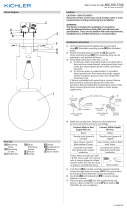
CAUTION – RISK OF SHOCK –
Disconnect Power at the main circuit breaker panel or main
fuse box before starting and during the installation.
1) Insert steel washer all the way into the slot on the slotted
coupler.
2) Slip the flexible washer onto the steel washer.
3) Pass the cord up through the glass and out through the
small hole at the top.
4) Pass the cord through the top cup.
5) Loosen threaded stud on strain relief. Insert cord into hole
in strain relief.
6) Slide the strain relief and top cup down the cord close to
the top of the glass.
7) Raise the socket into the glass. Rest the inside of the top
of the glass onto the inserted washers.
8) Place the top cup over the hexnut that is threaded to the
short pipe.
9) Thread the strain relief onto the short threaded pipe that is
protruding through the top cup. Tighten to secure the
socket fixture to the glass.
10) Tighten threaded stud on strain relief.
NOTE: Height of fixture must be adjusted before fixture is
mounted to ceiling.
11) Loosen threaded stud on strain relief on canopy. Insert cord
into hole in strain relief and up into canopy.
12) To adjust the length of the cord to achieve the desired
height of the mounted fixture: Carefully pull cord up into
canopy to shorten the height of fixture or carefully pull cord
down to lengthen the height of fixture. When desired height
is achieved, tighten threaded stud on strain relief.
13) Find the appropriate threaded holes on mounting strap.
Assemble mounting screws into threaded holes.
14) Attach mounting strap to outlet box. (Screws not provided).
Mounting strap can be adjusted to suit position of fixture.
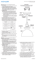
15) Make wire connections (connectors not provided.) Reference
chart below for correct connections and wire accordingly.
16) Push fixture to ceiling, carefully passing mounting screws
through holes in canopy.
17) Thread lock-up knobs onto mounting screws. Tighten
lock-up knobs to secure fixture to ceiling.
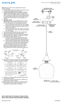
ATTENTION – RISQUE DE DÉCHARGES ÉLECTRIQUES –
Couper le courant au niveau du panneau du disjoncteur du
circuit principal ou de la boîte à fusibles principale avant de
procéder à l’installation.
1) Insérer entièrement la rondelle en acier dans la fente sur le
coupleur à fente.
2) Faire glisser la rondelle souple sur la rondelle en acier.
3) Passer le cordon à travers le verre et le ressortir par le
petit trou en haut.
4) Passer le cordon par la coupelle supérieure.
5) Desserrer le goujon fileté sur le réducteur de tension.
Insérer le cordon dans le trou du réducteur de tension
6) Faire glisser le réducteur de tension et la coupelle supéri
eur à proximité du haut du verre.
7) Élever la douille dans le cache. Placer l’intérieur de la
partie supérieure du verre sur les rondelles insérées.
8) Placer la coupelle supérieure sur l’écrou hexagonal qui est
fileté sur le tube court.
9) Installer le réducteur de tension sur le tuyau fileté court
qui sort de la coupelle supérieure. Serrer pour fixer la
douille sur le verre.
10) Serrer le goujon fileté sur le réducteur de tension.
REMARQUE: La hauteur du luminaire doit être réglée avant
d’installer le luminaire au plafond.
Connect Black or
Red Supply Wire to:
Connect
White Supply Wire to:
Black White
*Parallel cord (round & smooth) *Parallel cord (square & ridged)
Clear, Brown, Gold or Black
without tracer
Clear, Brown, Gold or Black
with tracer
Insulated wire (other than green)
with copper conductor
Insulated wire (other than green)
with silver conductor
*Note: When parallel wires (SPT I & SPT II)
are used. The neutral wire is square shaped
or ridged and the other wire will be round in
shape or smooth (see illus.)
Neutral Wire
Date Issued: 12/19/16 IS-43854-CB
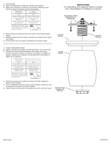
INSTRUCTIONS
For Assembling and Installing Fixtures in Canada
Pour L’assemblage et L’installation Au Canada
We’re here to help 866-558-5706
Hrs: M-F 9am to 5pm EST
Connecter le fil noir ou
rouge de la boite
Connecter le fil blanc de la boîte
A Noir A Blanc
*Au cordon parallèle (rond et lisse)
*Au cordon parallele (à angles droits el strié)
Au bransparent, doré, marron, ou
noir sans fil distinctif
Au transparent, doré, marron, ou
noir avec un til distinctif
Fil isolé (sauf fil vert) avec
conducteur en cuivre
Fil isolé (sauf fil vert) avec
conducteur en argent
*Remarque: Avec emploi d’un fil paralléle
(SPT I et SPT II). Le fil neutre est á angles
droits ou strié et l’autre fil doit étre rond ou
lisse (Voir le schéma).
Fil Neutre
11) Desserrer le goujon fileté sur le réducteur de tension du
cache. Insérez le cordon dans le réducteur de tension dans
le trou et dans le cache.
12) Pour régler la longueur du cordon à la hauteur souhaitée
pour le luminaire installé. Tirer soigneusement le cordon
vers le haut du cache pour raccourcir la hauteur du
luminaire ou tirer soigneusement le cordon vers le bas pour
allonger la hauteur du luminaire. Lorsque la hauteur souhaitée
est atteinte, serrer le goujon fileté.
13) Trouver les trous filetés appropriés sur la barrette de
montage. Vissez les vis de montage dans les trous filetés.
14) Visser la barrette de montage à la boite de jonction. (Vis non
fournies). La barrette de montage peut etre ajustée pour
convenir à la position de l’applique.
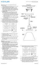
15) Connecter les fils (connecteurs non fournis). Se reporter au
tableau ci-dessous pour faire les connexions.
16) Pousser le luminaire vers le plafond en passant soigneusement
les vis de montage par les trous dans le cache.
17) Enfilez les boutons de verrouillage sur les vis de montage.
UL KNOT REQUIRED
AFTER ASSEMBLY
VIS DE MONTAGE
BOÎTE À PRISES
CONNECTEURS DE FIL
VIS DE L'ÉTRIER
DE MONTAGE
ÉTRIER DE MONTAGE
COUVERCLE
BOULES DE BLOCAGE
RONDELLE DE BLOCAGE
RONDELLE EN NOÉPRÈNE
COUPLEUR À FENTE
PIVOT
DOUILLE
TUBE FILTÉ
COUPELLE SUPÉRIEURE
RÉDUCTEUR DE TENSION
CORDON
RÉDUCTEUR DE TENSION
VERRE
RONDELLE EN ACIER
CONNECTORS
OUTLET BOX
STRAP MOUNTING SCREWS
MOUNTING STRAP
MOUNTING SCREWS
CANOPY
LOCKWASHERS /
LOCK-UP KNOBS /
STRAIN RELIEF
STRAIN RELIEF
CORD
TOP CUP
GLASS
SHORT THREADED PIPE
SOCKET
NEOPRENE WASHER
STEEL WASHER
SLOTTED COUPLER
WIRE
-
 1
1
-
 2
2
-
 3
3


Kichler Lighting 43854CH Manuel utilisateur
- Taper
- Manuel utilisateur
dans d''autres langues
Documents connexes
-
 Kichler Lighting 8043NI Manuel utilisateur
-
 Kichler Lighting 45910NI Manuel utilisateur
-
 Kichler Lighting 43852NI Manuel utilisateur
-
 Kichler Lighting 43853CH Manuel utilisateur
-
 Kichler Lighting 43851OZ Manuel utilisateur
-
 Kichler Lighting 43850CH Manuel utilisateur
-
 Kichler Lighting 43354CH Manuel utilisateur
-
 Kichler Lighting 44299WWW Manuel utilisateur
-
 Kichler Lighting 43489BKSLV Manuel utilisateur
-
 Kichler Lighting 45688NI Manuel utilisateur


