Tripp Lite POE-EXT-1G30WP Le manuel du propriétaire
- Catégorie
- Commutateurs réseau
- Taper
- Le manuel du propriétaire

1
Owner’s Manual
1-Port Gigabit PoE+
Water-Resistant Extender
Model: NPOE-EXT-1G30WP
1111 W. 35th Street, Chicago, IL 60609 USA • www.tripplite.com/support
Copyright © 2019 Tripp Lite. All rights reserved.
All trademarks are the property of their respective owners.
WARRANTY REGISTRATION
Register your product today and be automatically entered to win an
ISOBAR surge protector in our monthly drawing!
www.tripplite.com/warranty
Español 12 • Français 23 • Русский 34

2
Package Includes
Product Features
• NPOE-EXT-1G30WP Gigabit PoE+ Extender
• (x2) Water-Resistant Covers
• Owner’s Manual
• Save time and money by extending data and power over existing network
cables past the 100 m (328 ft.) limit
• Extend a 10/100/1000 Mbps application over longer distances by
cascading multiple extenders up to 500 m (1640 ft.)
• Supports all IEEE 802.3at- and IEEE 802.3af-compliant PoE/PoE+
devices (wireless LAN access points and bridges, VoIP, IP surveillance
cameras)
• Automatically detects and protects PoE/PoE+ equipment from being
damaged by incorrect installation (non-PoE devices only receive data)
• Compact aluminum case is IP65 rated for protection against water
splashes
• Plug and play—no additional power required
• Compact, wall-mountable design

3
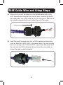
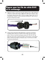
RJ45 Cable Wire and Crimp Steps
1. Strip an inch or so of the outer skin of a Cat5e/6 cable with a utility
knife. Separate and straighten the internal wires, and arrange them in
the proper order. Use a wire cutter to trim the wires evenly. Slide one of
the included water-resistant covers along the end of the cable.
2. Insert the neatly trimmed wires into an RJ45 modular connector plug
(such as Tripp Lite’s N230-100) in the correct order. Use your crimping
tool (such as Tripp Lite’s T100-001-TST) to press the cable jacket and
the wires into the RJ45 connector. Be sure to test the connection to
ensure the cable is working properly.

4
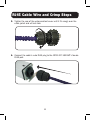
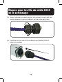
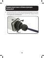
RJ45 Cable Wire and Crimp Steps
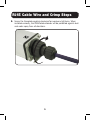
3. Tighten the rear of the water-resistant cover until it fits snugly over the
cable jacket and will not slide.
4. Connect the cable’s male RJ45 plug to the NPOE-EXT-1G30WP’s female
RJ45 port.

5
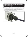
RJ45 Cable Wire and Crimp Steps
5. Screw the threaded coupling clockwise for maximum tightness. When
installed correctly, the IP65-rated extender will be protected against dust
and water spray from all directions.

6
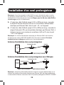
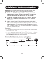
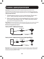
Single Extender Installation
Note: Prior to connecting the RJ45 cable to input/output ports, install the included
water-resistant dust caps onto the cable. Caps can be screwed onto the end of the port
connection (see RJ45 Cable Wire and Crimp Steps for more information).
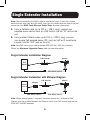
1. Using a Cat5e/6 cable (up to 100 m / 328 ft. long), connect your
powered source device (such as a PoE switch) into the “IN” port on the
unit.
2. Using another Cat5e/6 cable (up to 100 m / 328 ft. long), connect
your remote PoE powered device (PD) (such as VoIP or IP surveillance
camera) into the “OUT” port on the unit.
Note: Your PoE source must meet or exceed IEEE 802.3at / 802.3af standards.
Please see Maximum Supported Power table for more information.
Single Extender Installation Diagram
Single Extender Installation with Midspan Diagram
CameraPoE Extender
PoE
Switch
Max 100 m (328 ft.) Max 100 m (328 ft.)
CameraPoE Extender
Switch
(Non-PoE)
Midspan
Max 100 m (328 ft.) Max 100 m (328 ft.)
Note: Where external power is required, the power source (e.g.. midspan or PoE
injector) must be installed between the Ethernet switch (non-PoE source) and the first
NPOE-EXT-1G30WP extender.

7
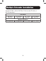
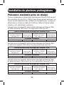
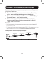
Multiple Extender Installation
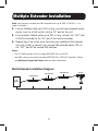
Note: You may only cascade four PoE extender units up to 500 m (1640 ft.) in a
single installation.
1. Using a Cat5e/6 cable up to 100 m long, connect your powered source
device (such as a PoE switch) into the “IN” port on the unit.
2. Using another Cat5e/6 cable up to 100 m long, connect the “OUT” port
of the first extender to the “IN” port of the second extender.
3. Repeat Step 2 up to two more times for each additional PoE extender
you wish to add, or connect your remote PoE powered device (PD) to
the “OUT” port of the second PoE extender.
Notes:
• The 4th PoE extender will only supply IEEE 802.3af up to 12W.
• Your PoE source must meet or exceed IEEE 802.3at / 802.3af standards. Please
see Maximum Supported Power table for more information.
Multi-Extender Installation Diagram
Camera
PoE Extender
PoE Extender
PoE Extender
PoE
Switch
Max 100 m (328 ft.) Max 100 m (328 ft.) Max 100 m (328 ft.) Max 100 m (328 ft.)

8
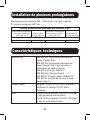
Multiple Extender Installation
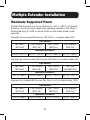
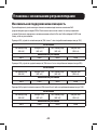
Maximum Supported Power
Multiple PoE Extenders can be connected every 100 m (328 ft.) for greater
distances. The actual figures depend on operating conditions. The range is
determined using 24 AWG or heavier Cat5e or Cat6 cable, except where
specified.
Examples for low power PoE devices (PoE Class 1, or require under 4W):
PoE Source
PoE switch
(802.3af)
15W midspan
(802.3af)
PoE+ switch
(802.3at)
30W midspan
(802.3at)
Maximum Distances
400 m / 1312 ft. 400 m / 1312 ft. 500 m / 1640 ft. 500 m / 1640 ft.
Examples for medium power PoE Devices (PoE Class 2, or require under 6W):
PoE Source
PoE switch
(802.3af)
15W midspan
(802.3af)
PoE+ switch
(802.3at)
30W mid-
span(802.3at)
Maximum Distances
300 m / 984 ft. 300 m / 984 ft. 400 m / 1312 ft. 400 m / 1312 ft.
Examples for full power PoE Devices (PoE Class 0 or 3, or require under 12W):
PoE Source
PoE switch
(802.3af)
15W midspan
(802.3af)
PoE+ switch
(802.3at)
30W midspan
(802.3at)
Maximum Distances
200 m / 656 ft. 200 m / 656 ft. 300 m / 984 ft. 300 m / 984 ft.

9
Multiple Extender Installation
Examples for PoE+ devices (PoE Class 4 that are under 22 watts, or
802.3at compliant):
PoE Source
PoE switch
(802.3af)
15W midspan
(802.3af)
PoE+ switch
(802.3at)
30W midspan
(802.3at)
Maximum Distances
Not applicable Not applicable 200 m / 656 ft. 200 m / 656 ft.

10
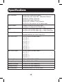
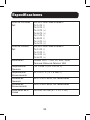
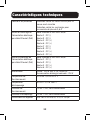
Specifications
IEEE Standards IEEE 802.3af (Power over Ethernet)
IEEE 802.3at (High-Power PoE+ Power over Ethernet)
IEEE 802.3 (10Base-T Ethernet)
IEEE 802.3ab (Gigabit Ethernet)
IEEE 802.3u (100Base-TX Fast Ethernet)
IEEE 802.3x (Flow control, for full duplex mode)
Media Support 100Base-TX Cat5 UTP/STP RJ45, 8 pin
1000Base-TX Cat5e/6 UTP/STP RJ45, 8 pin
Ports One RJ45 10/100/1000 Mbps Data + Power Input port
One RJ45 10/100/1000 Mbps Data + Power Output port
Protection Functions Short circuit protection for short GND
Overload protection for currents over 0.6A
PoE Pinout Input IEEE 802.3af/at Standard Mode A
Pin 1: DC (-)
Pin 2: DC (-)
Pin 3: DC (+)
Pin 6: DC (+)
Pin 7: DC (-)
Pin 8: DC (-)
Pin 4: DC (+)
Pin 5: DC (+)
PoE Pinout Output IEEE 802.3af/at Standard Mode A
Pin 1: DC (-)
Pin 2: DC (-)
Pin 3: DC (+)
Pin 6: DC (+)
Operating Temperature -10°C to 45°C / 14°F to 113°F
Storage Temperature 20°C to 70°C / -4°F to 158°F
Operating Humidity 0% to 90% RH, Non-Condensing
Storage Humidity 0% to 95% RH, Non-Condensing
Unit Dimensions 145 x 60 x 40 mm / 5.7 x 2.4 x 1.6 in.

11
Warranty and Product Registration
3-Year Limited Warranty
TRIPP LITE warrants its products to be free from defects in materials and workmanship for a period of three
(3) years from the date of initial purchase. TRIPP LITE’s obligation under this warranty is limited to repairing
or replacing (at its sole option) any such defective products. To obtain service under this warranty, you must
obtain a Returned Material Authorization (RMA) number from TRIPP LITE or an authorized TRIPP LITE service
center. Products must be returned to TRIPP LITE or an authorized TRIPP LITE service center with transportation
charges prepaid and must be accompanied by a brief description of the problem encountered and proof of
date and place of purchase. This warranty does not apply to equipment, which has been damaged by accident,
negligence or misapplication or has been altered or modified in any way.
EXCEPT AS PROVIDED HEREIN, TRIPP LITE MAKES NO WARRANTIES, EXPRESS OR IMPLIED, INCLUDING
WARRANTIES OF MERCHANTABILITY AND FITNESS FOR A PARTICULAR PURPOSE.
Some states do not permit limitation or exclusion of implied warranties; therefore, the aforesaid limitation(s) or
exclusion(s) may not apply to the purchaser.
EXCEPT AS PROVIDED ABOVE, IN NO EVENT WILL TRIPP LITE BE LIABLE FOR DIRECT, INDIRECT, SPECIAL,
INCIDENTAL OR CONSEQUENTIAL DAMAGES ARISING OUT OF THE USE OF THIS PRODUCT, EVEN IF ADVISED
OF THE POSSIBILITY OF SUCH DAMAGE. Specifically, TRIPP LITE is not liable for any costs, such as lost profits
or revenue, loss of equipment, loss of use of equipment, loss of software, loss of data, costs of substitutes,
claims by third parties, or otherwise.
Product Registration
Visit www.tripplite.com/warranty today to register your new Tripp Lite product. You’ll be automatically entered
into a drawing for a chance to win a FREE Tripp Lite product!*
* No purchase necessary. Void where prohibited. Some restrictions apply. See website for details.
WEEE Compliance Information for Tripp Lite Customers and Recyclers
(European Union)
Under the Waste Electrical and Electronic Equipment (WEEE) Directive and implementing regulations,
when customers buy new electrical and electronic equipment from Tripp Lite they are entitled to:
• Send old equipment for recycling on a one-for-one, like-for-like basis (this varies depending on
the country)
• Send the new equipment back for recycling when this ultimately becomes waste
Use of this equipment in life support applications where failure of this equipment can reasonably be expected
to cause the failure of the life support equipment or to significantly affect its safety or effectiveness is not
recommended.
Tripp Lite has a policy of continuous improvement. Specifications are subject to change without notice. Photos
and illustrations may differ slightly from actual products.
1111 W. 35th Street, Chicago, IL 60609 USA • www.tripplite.com/support
19-06-244 93-38F9_RevB

12
Manual del Propietario
Extensor Resistente al
Agua Gigabit PoE+
de 1 Puerto
Modelo: NPOE-EXT-1G30WP
1111 W. 35th Street, Chicago, IL 60609 EE UU • www.tripplite.com/support
Copyright © 2019 Tripp Lite. Todos los derechos reservados.
Todas las marcas registradas son propiedad de sus respectivos propietarios.
English 1 • Français 23 • Русский 34

13
El Paquete Incluye
Características del Producto
• NPOE-EXT-1G30WP – Extensor Gigabit PoE+
• (x2) Cubiertas Resistentes al agua
• Manual del Propietario
• Ahorre tiempo y dinero extendiendo los datos y la energía sobre los
cables de red existentes más allá de los 100 m [328 pies] límite
• Extienda una aplicación 10Mbps / 100Mbps / 1000Mbps a distancias
mayores colocando en cascada múltiples extensores hasta 500 m
[1640 pies]
• Soporta todos los dispositivos PoE y PoE+ que cumplen con IEEE
802.3at y IEEE 802.3af (Puentes y puntos de acceso LAN inalámbricos,
VoIP, cámaras de vigilancia IP, etc.)
• Detecta automáticamente y protege equipo PoE y PoE+ contra daños por
una instalación incorrecta (Los dispositivos sin PoE únicamente reciben
datos)
• La compacta caja de aluminio está clasificada IP65 para protección
contra salpicaduras de agua
• Conectar y Usar—No requiere alimentación adicional
• Diseño compacto, instalable en la pared

14
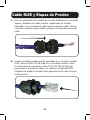
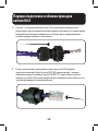
Cable RJ45 y Etapas de Presión
1. Pele una pulgada de forro exterior de un cable Cat5e/6 con una cuchilla.
Separe y enderece los cables internos y organícelos en el orden
adecuado. Use un cortador de cables para recortar los cables. Deslice
una de las cubiertas impermeables incluidas a lo largo del extremo del
cable.
2. Inserte los cables cuidadosamente recortados en un conector modular
RJ45 (como el N230-100 de Tripp Lite) en el orden correcto. Utilice
su herramienta de compresión (como T100-001-TST de Tripp Lite)
para presionar la funda del cable y los cables en el conector RJ45.
Asegúrese de probar la conexión para garantizar que el cable funciona
correctamente.

15
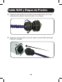
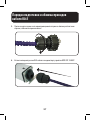
Cable RJ45 y Etapas de Presión
3. Apriete la parte trasera de la cubierta impermeable hasta que encaje
perfectamente sobre la funda del cable y no se deslice.
4. Conecte el conector RJ45 macho del cable al puerto RJ45 hembra del
NPOE-EXT-1G30WP.

16
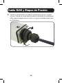
Cable RJ45 y Etapas de Presión
5. Atornille el acoplamiento roscado en sentido horario para un apriete
máximo. Cuando se instale correctamente, el extensor con clasificación
IP65 estará protegido contra el polvo y el agua pulverizada desde todas
las direcciones.

17
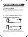
Instalación de un solo Extensor
Nota: Antes de conectar el cable RJ45 a los puertos de entrada o salida, instale las
tapas anti polvo, resistentes al agua, sobre el cable. Las tapas anti polvo pueden
atornillarse en el extremo de la conexión del puerto (para información adicional,
consulte Cable RJ45 y Etapas de Presión).
1. Usando un cable Cat5e / Cat6 (hasta 100 m [328 pies] de largo),
conecte su dispositivo fuente con alimentación (como un switch PoE) en
el puerto “IN” en la unidad.
2. Usando otro cable Cat5e / Cat6 (hasta 100 m [328 pies] de largo),
conecte su dispositivo remoto alimentado por PoE (PD) (como VoIP o
cámara de vigilancia IP) en el puerto “OUT” en la unidad.
Nota: Su fuente de PoE debe cumplir o superar los estándares IEEE 802.3at /
802.3af. Consulte la tabla Potencia Máxima Soportada para obtener más
información.
Diagrama de Instalación de Extensor Sencillo
Diagrama de Instalación de un solo Extensor con Midspan
CámaraExtensor PoE
Switch
PoE
Máximo 100 m [328 pies] Máximo 100 m [328 pies]
CámaraEstensor Poe
Switch
sin PoE
Midspan
Máximo 100 m [328 pies] Máximo 100 m [328 pies]
Nota: Donde se requiera alimentación externa, la fuente de alimentación (p.e.
midspan o inyector PoE) debe instalarse entre el switch Ethernet (fuente sin PoE) y el
primer extensor NPOE-EXT-1G30WP.

18
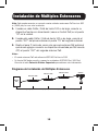
Instalación de Múltiples Extensores
Nota: Solo puede conectar en cascada cuatro unidades extensoras PoE hasta a 500
m [1640 pies] en una sola instalación.
1. Usando un cable Cat5e / Cat6 de hasta 100 m de largo, conecte su
dispositivo fuente con alimentación (como un Switch PoE) en el puerto
“IN” en la unidad.
2. Usando otro cable Cat5e / Cat6 de hasta 100 m de largo, conecte el
puerto “OUT” del primer extensor al puerto “IN” del segundo extensor.
3. Repita el paso 2 hasta dos veces más por cada extensor PoE adicional
que desee agregar o conecte su dispositivo alimentado por PoE remoto
(PD) al puerto “OUT” del segundo extensor PoE.
Notas:
• El cuarto extensor PoE solo alimenta IEEE 802.3af hasta 12W.
• Su fuente PoE debe cumplir o superar los estándares IEEE 802.3at / 802.3af.
Consulte la tabla Potencia Máxima Soportada para obtener más información.
Diagrama de Instalación de Múltiples Extensores
Cámara
Extensor PoE
Extensor PoE
Extensor PoE
Switch
PoE
Máximo 100 m [328 pies]
Máximo 100 m [328 pies]
Máximo 100 m [328 pies]
Máximo 100 m [328 pies]

19
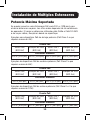
Instalación de Múltiples Extensores
Potencia Máxima Soportada
Se pueden conectar varios Extensores PoE cada 100 m [328 pies] para
alcanzar distancias mayores. Las cifras reales dependen de las condiciones
de operación. El rango se determina utilizando cable Cat5e o Cat6 24 AWG
o de mayor calibre, excepto en donde se especifique.
Ejemplos para dispositivos PoE de de baja potencia (PoE Clase 1 o que
requiera menos de 4W):
Fuente PoE
Switch PoE
(802.3af)
Midspan de 15W
(802.3af)
Switch PoE+
(802.3at)
Midspan de 30W
(802.3at)
Distancias Máximas
400 m [1312 pies] 400 m [1312 pies] 500 m [1640 pies] 500 m [1640 pies]
Ejemplos de dispositivos PoE de mediana potencia (PoE Clase 2 o que
requiera menos de 6W):
Fuente PoE
Switch PoE
(802.3af)
Midspan de 15W
(802.3af)
Switch PoE+
(802.3at)
Midspan de 30W
(802.3at)
Distancias Máximas
300 m [984 pies] 300 m [984 pies] 400 m [1312 pies] 400 m [1312 pies]
Ejemplos de dispositivos PoE de máxima potencia (PoE Clase 0 o 3 o que
requiera menos de 12W):
Fuente PoE
Switch PoE
(802.3af)
Midspan de 15W
(802.3af)
Switch PoE+
(802.3at)
Midspan de 30W
(802.3at)
Distancias Máximas
200 m [656 pies] 200 m [656 pies] 300 m [984 pies] 300 m [984 pies]

20
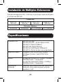
Instalación de Múltiples Extensores
Ejemplos de dispositivos PoE+ (PoE Clase 4 que tengan menos de 22 watts
o cumplan con 802.3at):
Fuente PoE
Switch PoE
(802.3af)
Midspan de 15W
(802.3af)
Switch PoE+
(802.3at)
Midspan de 30W
(802.3at)
Distancias Máximas
No aplicable No aplicable
200 m [656 pies] 200 m [656 pies]
Especificaciones
Estándares IEEE IEEE 802.3af (PoE)
IEEE 802.3at (PoE + de Alta Potencia (PoE)
IEEE 802.3 (Ethernet 10Base-T)
IEEE 802.3ab (Gigabit Ethernet)
IEEE 802.3u (Fast Ethernet 100Base-TX)
IEEE 802.3x (Control de flujo, para modo dúplex)
Soporte de Medios 100Base-TX Cat5 UTP/STP RJ45, 8 pines
1000Base-TX Cat5e / Cat6 UTP/STP RJ45,
8 pines
Puertos Un puerto de Entrada RJ45 10Mbps / 100Mbps /
1000Mbps Datos + Alimentación
Un puerto de Salida RJ45 10Mbps / 100Mbps /
1000Mbps Datos + Alimentación
Funciones de
Protección
Protección contra cortocircuito para corto a tierra
Protección contra sobrecarga para corrientes
superiores a 0.6A
La page est en cours de chargement...
La page est en cours de chargement...
La page est en cours de chargement...
La page est en cours de chargement...
La page est en cours de chargement...
La page est en cours de chargement...
La page est en cours de chargement...
La page est en cours de chargement...
La page est en cours de chargement...
La page est en cours de chargement...
La page est en cours de chargement...
La page est en cours de chargement...
La page est en cours de chargement...
La page est en cours de chargement...
La page est en cours de chargement...
La page est en cours de chargement...
La page est en cours de chargement...
La page est en cours de chargement...
La page est en cours de chargement...
La page est en cours de chargement...
La page est en cours de chargement...
La page est en cours de chargement...
La page est en cours de chargement...
La page est en cours de chargement...
-
 1
1
-
 2
2
-
 3
3
-
 4
4
-
 5
5
-
 6
6
-
 7
7
-
 8
8
-
 9
9
-
 10
10
-
 11
11
-
 12
12
-
 13
13
-
 14
14
-
 15
15
-
 16
16
-
 17
17
-
 18
18
-
 19
19
-
 20
20
-
 21
21
-
 22
22
-
 23
23
-
 24
24
-
 25
25
-
 26
26
-
 27
27
-
 28
28
-
 29
29
-
 30
30
-
 31
31
-
 32
32
-
 33
33
-
 34
34
-
 35
35
-
 36
36
-
 37
37
-
 38
38
-
 39
39
-
 40
40
-
 41
41
-
 42
42
-
 43
43
-
 44
44


Tripp Lite POE-EXT-1G30WP Le manuel du propriétaire
- Catégorie
- Commutateurs réseau
- Taper
- Le manuel du propriétaire
dans d''autres langues
Documents connexes
-
Tripp Lite POE-EXT-1G30WP Le manuel du propriétaire
-
-
Tripp Lite NPOE-30W-1G Le manuel du propriétaire
-
-
Tripp Lite NPOE-SPL-G-5VMU Guide de démarrage rapide
-
Tripp Lite NG8POE Le manuel du propriétaire
-
Tripp Lite NGS8C2POE Le manuel du propriétaire
-
-
-
Tripp Lite B110-SP-POE Guide de démarrage rapide
Autres documents
-
Rosewill RC-GP1008 8-Port 10/100/1000 Mbps Gigabit PoE Switch Manuel utilisateur
-
Intellinet PoE-Powered 5-Port Gigabit Switch with PoE Passthrough Mode d'emploi
-
Black Box LPR1111 Manuel utilisateur
-
Uniden UCSWITCH9 Le manuel du propriétaire
-
DELTA DORE SW4 POE Guide d'installation
-
-
 AmazonBasics B07RK3VP7W Manuel utilisateur
-
CommScope PFU-P-C-O-060-01 Manuel utilisateur
-
Westermo PII-2G Mode d'emploi
-
Trendnet TPE-E100 Fiche technique
