NewMac NM-175K Operating Instructions Manual
- Catégorie
- Cheminées
- Taper
- Operating Instructions Manual

Portable Forced Air Heaters
NM-75K / NM-125K / NM-175K / NM-215K
852945C-3304H
PRO
NEWMAC
NEWMAC
227 Industrial Park Road
South Pittsburg, TN 37380
(800) 750-2723
DANGER:
Improper use of this heater can result in serious injury or death from burns, re, explosion, electrical shock, and/
or carbon monoxide poisoning.
DANGER:
Service must be performed by a qualied service technician. Unvented portable heaters use air (oxygen) from
the area in which it is used. Adequate combustion and ventilation air must be provided. Refer to instructions.
WARNING:
Before using this heater, please read this OPERATING INSTRUCTION very carefully. This USER’S MANUAL has been
designed to instruct you as to the proper manner in which to assemble, maintain, store, and most importantly,
how to operate the heater in a safe and efcient manner. Do not allow anyone who has not read these
instructions to assemble, light, adjust or operate the heater.
CALIFORNIA PROPOSITION 65 WARNING:
This product can expose you to chemicals including carbon monoxide, which
is known to the State of California to cause cancer, birth defects and/or other
reproductive harm. For more information, go to www.P65warnings.ca.gov
Ce produit peut vous exposer à des produits chimiques, y compris le
monoxyde de carbone, qui est connu dans l'État de Californie pour causer
le cancer, des malformations congénitales et / ou d'autres problèmes de
reproduction. Pour plus d'informations, visitez www.P65warnings.ca.gov

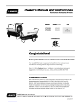
Product Information
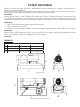
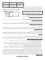
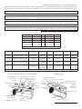
Specication
NM-75K NM-125K NM-175K / NM-215K
H 15.9 inch (405 mm) 26.4 inch (670 mm) 25 inch (635 mm)
W 11.8 inch (300 mm) 21.5 inch (545 mm) 23.2 inch (590 mm)
L 29.1 inch (740 mm) 35.2 inch (893 mm) 39.5 inch (1003 mm)
H
L
W
Model NM-75K
H
L
W
Model NM-125K, NM-175K, NM-215K
DIMENSIONS
Please read and save these instructions. Read carefully before attempting to assemble, install, operate or
maintain the product described.
Protect yourself and others by observing all safety information. Failure to comply with instructions could result in
personal injury and/or property damage! Retain instructions for future reference.
Description
Models NM-75K, NM-125K, NM-175K, NM-215K heaters are 75,000 to 210,000btu/hr heaters. These heaters use
1-K Kerosene for combustion, and electricity to run the fan. It is primarily intended for temporary heating of well
ventilated buildings under construction, alteration, or repair. This heater may be used in agricultural, industrial and
commercial environments.
Unpacking
1. Remove all packing items applied to heater for shipment.
2. Remove all items from carton.
3. Check all items for shipping damage. If heater is damaged, promptly inform dealer where you purchased
heater.
Introduction
Please read this USER’S MANUAL carefully. It will show you how to assemble, maintain and operate this heater
safely and efciently to obtain the full benets of its many features.
Consumer
Save these instructions for future reference

-3-
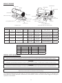
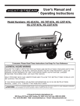
Upper Shell
Fan Guard
Fuel Gauge
Fuel Cap
Lower Shell
Side Cover Lamp
Power/Reset Switch
Fuel Tank
Power Cord
Handle
Upper Shell
Handle Rear
Fan Guard
Fuel Gauge
Fuel Cap
Side Cover Lamp
Thermostat Knot
Power/Reset Switch
Fuel Tank
Power Cord
Model NM-75K Model NM-125K, NM-175K, NM-215K
PRODUCT FEATURES
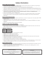
GENERAL SAFETY INFORMATION
DANGER:
Indicates an imminently hazardous situation which, if not avoided, WILL result in death or serious injury.
WARNING:
Indicates a potentially hazardous situation which, if not avoided, COULD result in death or serious injury.
CAUTION:
Indicates a potentially hazardous situation which, if not avoided, MAY result in minor or moderate injury.
WARNING:
Never leave the heater unattended while burning!
For optimal performance of this heater it is strongly suggested that 1-K kerosene be used. 1-K kerosene has
been rened to virtually eliminate contaminants, such as sulfur, which can cause a rotten egg odor during the
operation of the heater.
Electrical Specications
Model Electrical Input Watt Fuse Spark Plug Gap
NM-75K 120V, 60Hz 160 250V/10 amp. .140”(3.5mm)
NM-125K 120V, 60Hz 250 250V/10 amp. .140”(3.5mm)
NM-175K 120V, 60Hz 298 250V/10 amp. .140”(3.5mm)
NM-215K 120V, 60Hz 324 250V/10 amp. .140”(3.5mm)
General Specications
Model
Type of
Fuel
Input Rating
(Btu/kW)
Pump
Pressure
Fuel Tank
Capacity
Fuel
Consumption
Size L x W x H Weight
NM-75K
Kerosene 75,000/21.8 4.7 PSI
5.3 gal
(20 Liter)
0.55 gal/h
(2.1 l/h)
29.1X11.8X15.9(inch)
740X300X405(mm)
28.2 lbs
(12.8 Kg)
NM-125K
Kerosene 125,000/36.3 4.9 PSI
10.6 gal
(40 Liter)
0.95 gal/h
(3.6 l/h)
35.2X21.5X26.4(inch)
893X545X670(mm)
53.8 lbs
(24.4 Kg)
NM-175K
Kerosene 175,000/50.9 4.9 PSI
13.2 gal
(50 Liter)
1.32 gal/h
(5.0 l/h)
39.5X23.2X25(inch)
1003X590X635(mm)
60 lbs
(27.2 Kg)
NM-215K
Kerosene 210,000/61 5.5 PSI
13.2 gal
(50 Liter)
1.58 gal/h
(6.0 l/h)
39.5X23.2X25(inch)
1003X590X635(mm)
62 lbs
(28.2 Kg)

-4-
Safety Information
RISK OF INDOOR AIR POLLUTION
• Use this heater only in well ventilated areas! Provide at least a three square foot (2,800 sq cm) opening of
outside air for every 100,000 Btu/hr of heater rating.
• People with breathing problems should consult a physician before using the heater.
• Carbon Monoxide Poisoning: Early signs of carbon monoxide poisoning resemble u-like symptoms such as
headaches, dizziness, and/or nausea. If you have these symptoms, your heater may not be working properly.
• Get fresh air at once! Have the heater serviced.
• Some people are more affected by carbon monoxide than others. These include pregnant women, those
with heart or lung problems, anemia, or those under the inuence of alcohol, or at high altitudes.
• Never use this heater in living or sleeping areas.
• Service must be performed by a qualied service technician. Unvented portable heaters use air (oxygen)
from the area in which it is used. Adequate combustion and ventilation air must be provided. Refer to
instructions.
RISK OF BURNS/FIRE/EXPLOSION
• NEVER use fuels such as gasoline, benzene, paint thinners, or other oil compounds in this heater (RISK OF FIRE
OR EXPLOSION).
• NEVER use this heater where ammable vapors may be present.
• NEVER rell the heater’s fuel tank while heater is operating or still hot. This heater is EXTREMELY HOT while in
operation.
• Keep all combustible materials away from this heater.
PROPER COOLING BEFORE UNPLUGGING
• Allow the unit to cool for three minutes before unplugging.
• Before heater is moved, it must be stopped and unplugged. BEFORE MOVING the heater, wait until it has
totally cooled off and make sure the oil tank cap is securely xed.
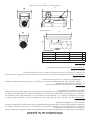
MINIMUM CLEARANCES
• NEVER block air inlet (rear) or air outlet (front) of heater.
• NEVER use duct work in front or at rear of
• NEVER move or handle heater while still hot.
• NEVER transport heater with fuel in its tank.
• When used with optional thermostat or if equipped with a thermostat, the heater may start at any time.
• ALWAYS locate heater on a stable and level surface.
• ALWAYS keep children and animals away from heater.
• Use 1-K kerosene in this heater. #1 fuel (oil is a suitable substitute).
• Bulk fuel storage should be a minimum of 25 ft. from heaters, torches, portable generators, or other sources
of ignition. All fuel storage should be in accordance with federal, state, or local authorities.
RISK OF ELECTRIC SHOCK
• Use only the electrical power (voltage and frequency) specied on the model plate of the heater. Use only
a three-prong, grounded outlet and extension cord.
• ALWAYS install the heater so that it is not directly exposed to water spray, rain, dripping water, or wind.
• ALWAYS unplug the heater when not in use.
Front 110” (2.8m)
Ceiling 59” (1.5m)
Side/Rear 37.4” (0.95m)
CANADIAN RESIDENTS:
THE INSTALLATION OF THE EQUIPMENT SHALL BE
IN ACCORDANCE WITH THE REGULATION OF
AUTHORITIES HAVING JURISDICTION AND CSA
STANDARD B139
US RESIDENTS:
THE INSTALLATION OF THE EQUIPMENT SHALL BE
IN ACCORDANCE WITH THE REGULATION OF
AUTHORITIES HAVING JURISDICTION AND NFPA 31

-5-
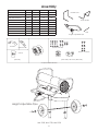
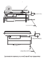
Handle Front
Rear Handle
Axle
Height Adjustable Pipe
Handle
Wheels
Washer
Screws and Nuts
Screws, and Nuts
(NM-125K / NM-175K / NM-215K)
Screws
(NM-75K)
Component Identification
Shaft fixed Bkt
Cap Nut
NM-125K, NM-175K, NM-215K
Height Adjustable Pipe
Assembly
Model NM-75K NM-125K NM-175K NM-215K
Height Adjustment Pipe No Yes Yes Yes
Wheels No Yes Yes Yes
Shaft xed Bracket No Yes Yes Yes
Front-Handle No Yes Assembly Assembly
Rear-Handle No Yes Assembly Assembly
Axle No No Yes Yes Yes
Handle Yes No No No
Screws Yes No No No
Screws and Nuts No Yes Yes Yes
Cotter Pin and Washer No Yes Yes Yes

-6-
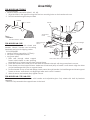
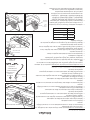
Assembly
FOR MODELS NM-75KONLY
TOOLS REQUIRED
• Medium Phillips screwdriver (size #1, #2, #3).
1. Align the holes in the upper housing with the two mounting holes on the handle as shown.
2. Secure handle through holes provided.
FOR MODELS NM-125K
This model is furnished with wheels and
handles. Wheels, handles and mounting
hardware are found in shipping carton.
TOOLS REQUIRED
• Medium Phillips screwdriver. (2.75inch)
• M5 open, or adjustable wrench.
• Long nose pliers
1. Slide axle through wheel support
frame. Install wheels on axle, pointing
extended hub of wheel toward wheel support frame.
2. Place at washers and cotter pin on axle ends and bend cotter pin with long nose pliers to secure.
3. Place heater on wheel support frame. Make sure air inlet end (rear) of heater is over wheels. Align the holes
on fuel tank ange with holes on support frame.
4. Position handle on top of fuel tank ange. Insert screws through handles, fuel tank ange and wheel support
frames as shown, and attach nuts nger tight after each screw is inserted.
5. After all screws are inserted, rmly tighten all nuts.
FOR MODELS NM-175K, NM-215K
These models are already assemble with handles and adjustable pipe. Only wheels with shaft by brackets
assemble.
CAUTION: Fully assemble the support frame to the tank.
Models NM-125K, NM-175K, NM-215K
Handle
Air Inlet
Fuel Tank Flange
Axle
Wheel
Wheel support
Frame
Thermostat
Knob
Handle Installation NM-75K
Screw
Handle

-7-
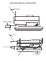
Guard Assembly (For Canada Only)
Interception
Guard
Interception
Guard

-8-
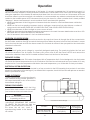
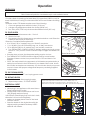
OPERATION
KEROSENE (1-K) For optimal performance of this heater, it is strongly suggested that 1-K kerosene be used. 1-K
kerosene has been rened to virtually eliminate contaminants, such as sulfur, which can cause a rotten egg odor
during the operation of the heater. Be advised that these fuels do not burn as clean as 1-K kerosene, and care
should be taken to provide more fresh air ventilation to accommodate any added contaminants that may be
added to the heated space. NOTE: Kerosene should only be stored in a blue container that is clearly marked
“kerosene”. Never store kerosene in a red container. Red is associated with gasoline.
• NEVER store kerosene in the living space. Kerosene should be stored in a well ventilated area outside the
living area.
• NEVER use fuel such as gasoline, benzene, alcohol, white gas, camp stove fuel, paint thinners, or other oil
compounds in this heater (THESE ARE VOLATILE FUELS THAT CAN CAUSE A FIRE OR EXPLOSION).
• NEVER store kerosene in direct sunlight or near a source of heat.
• NEVER use kerosene that has been stored from one season to the next. Kerosene deteriorates over time. OLD
KEROSENE WILL NOT BURN PROPERLY IN THIS HEATER.
• Use 1-K kerosene in this heater. #1 fuel is a suitable substitute.
OVERVIEW OF HEATER DESIGN
Fuel System: This heater is equipped with an electric air pump that forces air through the air line connected to
the fuel intake, and then through a nozzle in the burner head. When air passes in front of the fuel intake, it causes
fuel to rise from the tank and into the burner nozzle. This fuel and air mixture is then sprayed into the combustion
chamber in a ne mist.
IGNITION
The electronic igniter sends voltage to a specially designed spark plug. The spark plug ignites the fuel and
air mixture described. The Air System: The heavy duty motor turns a fan that forces air into and around the
combustion chamber. Here, the air is heated and then forced out the front of the heater.
THE SAFETY SYSTEM
Temperature Limit Control: This heater is equipped with a Temperature Limit Control designed to turn the heater
off should the internal temperature rise to an unsafe level. If this device activates and turns your heater off, it may
require service. Once the temperature falls below the reset temperature, you will be able to start your heater.
ELECTRICAL SYSTEM PROTECTION
This heater’s electrical system is protected by a fuse mounted to the PCB Assembly that protects it and other
electrical components from damage. If your heater fails to operate, check this fuse rst and replace as needed.
Refer to specication chart.
FLAME-OUT SENSOR
Utilizes a photocell to monitor the ame in
burn chamber during normal operation. It
will cause the heater to shut off should the
burner ame extinguish.
FUELING YOUR HEATER
Never ll the heater fuel tank in the living
space: ll the tank outdoors. Do not overll
your heater and be sure heater is level.
IMPORTANT: REGARDING FIRST IGNITION
OF HEATER. The rst time you light the
heater, it should be done OUTDOORS.
This allows the oils, etc., used in
manufacturing heater to be burned
off outside.
Overview of Heater Design
WARNING:
Never rell fuel tank when heater
is operating or still hot.
MODELS
Internal Shut-Off Temp.
+/-10 Degrees
Reset Temp.
+/-10 Degrees
NM-75K, NM-125K,
NM-175K, NM-215K
176°F (80°C) 158°F (70°C)
Operation

-9-
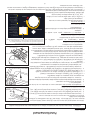
VENTILATION
Provide a fresh air opening of at least three (3) square feet (2,800 sq. cm) for
each 120,000 btu/hr. rating. Provide extra fresh air if more heaters are being
used.
Example: A NM-175K heater requires one of the following:
1. A two-car garage door raised six inches (15.24 cm).
2. A single-car garage door raised nine inches (22.86 cm).
3. Two, thirty inch (76.20 cm) windows raised fteen inches (38.1 cm).
TO START HEATER
1. Fill fuel tank with kerosene or No. 1 fuel oil.
2. Attach fuel cap.
3. Plug power cord into three prong, grounded extension cord. Extension
cord must be at least six feet long.
Extension Cord Wire Size Requirements:
• 6 to 10 feet (1.8 to 3 meters) long, use 18 AWG conductor.
• 11 to 100 feet (3.4 to 30.53 meters) long, use 16 AWG conductor.
• 101 to 200 feet (30.8 to 61 meters) long, use 14 AWG conductor.
4. Turn THERMOSTAT CONTROL KNOB to desired setting and push power
switch to “ON” position. Power indicator lamp will light and heater will
start.
• If heater does not start, the thermostat setting may be too low.
• Turn THERMOSTAT CONTROL KNOB to higher position to start heater.
If heater still does not start, turn power switch to OFF and then to ON
position.
• NOTE: The major electrical components of this heater are protected by a
safety fuse mounted to the PCB board. If your heater fails to start, check
this fuse rst and replace as necessary. You should also check your power
source to insure that proper voltage and frequency are being supplied
to the heater.
TO SHUT DOWN HEATER
Turn power switch to “OFF” and unplug power cord.
TO RESTART HEATER
1. Wait 10 seconds after stopping heater.
2. Repeat steps under, “TO START HEATER.”
ELECTRICAL OUTLET
• Shock Hazard
• Never plug in an appliance with more than a
5amp rating into this outlet.
• Always keep outlet covered when not in use.
120V 30amp max(non fused).
IMPORTANT: Reinstall plug fully into hole in tank;
otherwise it will not seal completely.
• Make sure storage place is free of dust and
corrosive fumes.
• Store the heater in the original box with the
original packing material and keep USER’S
MANUAL with heater.
The room temperature display will indicate the following:
* When the temperature is less than 0° F, the display says “LO”
* When the temperature is more than 99° F, the display says “HI”
* Between 0° F and 99° F the display shows the actual room temperature
Power
Reset
Switch
Lamp
Thermostat
Control Knob
Room Temp.Display
Controls for All Models
Lint Filter
Air Out Put Filter
Intake Filter
End Filter Cover
Operation
CAUTION:
Risk of indoor air pollution. Use heater only in well ventilated areas.
Power Reset Switch

-10-
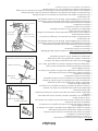
USE ORIGINAL EQUIPMENT REPLACEMENT PARTS. Use of
third party or other alternate components will void warranty
and may cause unsafe operating conditions.
FUEL TANK
Flush every 200 hours of operation or as needed. DO NOT
ush with water, use fresh 1-K kerosene only.
AIR INTAKE FILTER
Wash and dry with soap and water every 500 hours of
operation, or as needed.
• Remove screws along side of heater using medium
Phillips screwdriver.
• Lift off upper shell.
• Remove fan guard.
• Wash or replace air intake lter.
• Reinstall fan guard and upper shell.
AIR OUTPUT FILTER, LINT FILTER REPLACE EVERY 500
HOURS OF OPERATION OR ONCE A YEAR
• Remove upper shell and fan guard.
• Remove end lter cover screws using medium Phillips
screwdriver.
• Remove end lter cover.
• Replace air output and lint lter.
• Reinstall end lter cover.
• Reinstall fan guard and upper shell.
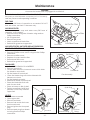
FAN BLADES
• CLEAN EVERY SEASON OR AS NEEDED
• Remove upper shell.
• Use M6 Allen wrench to loosen set screw which holds
fan blade to motor shaft.
• Slip fan blade off motor shaft.
• Clean fan blade using soft cloth moistened with
kerosene or solvent.
• Dry fan blade thoroughly.
• Reinstall fan blade to motor shaft.
• Place fan blade hub ush with
end of motor shaft.
• Place set screw on at of shaft.
• Tighten screw rmly (40-50 inch
pounds/ 4.5-5.6 N-m). Reinstall
upper shell.
NOZZLE
Clean nozzle as needed
• Open upper shell.
• Remove fan blade.
• Remove fuel and air line hoses
from burner head.
• Remove igniter wire from spark
plug.
• Remove spark plug from Nozzle
rod using medium Phillips
screwdriver.
Fan Assembly
Fan Blade
Flush
Moter Shaft
Set Screw
Fuel Hose
Ignitor
Wire
Burner Head
Air Hose
Nozzle
Rod
Spark Plug
Fuel Hose
Fitting
Air Hose Fitting
Lint Filter
Air Out Put Filter
Intake Filter
End Filter Cover
Maintenance
WARNING:
Never service heater while it is plugged in or while hot!

-11-
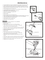
• Turn the Nozzle rod to anti clockwise and separate with Burner head.
• Carefully remove nozzle from Nozzle rod using 5/8” socket wrench.
• Blow compressed air through face of nozzle (This will remove any dirt).
• Reinstall nozzle into Nozzle rod and tighten rmly (80-100 inch-pounds).
• Reinstall spark plug into Nozzle rod.
• Turn the Nozzle rod to clockwise and Assemble with Burner Head.
• Attach igniter wire to spark plug.
• Attach fuel and air line hoses to Nozzle rod.
• Reinstall fan blade and upper shell.
• Remove upper shell.
• Remove fan.
• Remove igniter wire from spark plug.
• Remove spark plug from Nozzle head using medium Phillips screwdriver.
• Clean and regap spark plug electrodes to .140” (3.5 mm) gap.
• Reinstall spark plug into Nozzle head.
• Attach igniter wire to spark plug.
• Reinstall fan and upper shell.
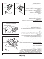
PHOTOCELL
• CLEAN PHOTOCELL ANNUALLY OR AS NEEDED.
• Remove upper shell.
• Remove fan.
• Remove photocell from its mounting bracket.
• Clean photocell lens with cotton swab. TO REPLACE:
Remove side cover near power switch.
• Disconnect wires from circuit board and remove photocell.
• Install new photocell and attach wires to circuit board.
• Reinstall fan and upper shell.
• Remove upper shell.
• Remove fan.
• Remove photocell from its mounting bracket.
• Clean photocell lens with cotton swab. TO REPLACE:
Remove side cover near power switch.
• Disconnect wires from power switch and remove side
cover.
• Disconnect wires from circuit board and remove photocell.
• Install new photocell and attach wires to circuit board.
• Replace switch wires to power switch and side cover.
• Replace fan and upper shell.
Nozzle Face
Nozzle Rod
Nozzle
Spark Plug Replacement
Nozzle Rod
Spark Plug
Gap
PHOTO CELL
3VE49A Only
WIRE
CIRCUIT BOARD
Photocell Replacement for
Maintenance

-12-
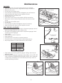
FUEL FILTER
• Clean or replace twice per heating season or as needed.
• Remove side cover screws using medium Phillips screwdriver.
• Remove side cover.
• Pull fuel line off fuel lter neck.
• Turn fuel lter counterclockwise 90 degrees, pull, and remove.
• Wash fuel lter with clean fuel and replace in tank.
• Attach fuel line to fuel lter neck.
• Reinstall side cover.
• Open side cover screws using medium Phillips screwdriver.
• Disconnect switch wires from power switch and remove side
cover.
• Pull fuel line off fuel lter neck.
• Pull fuel line.
• Turn fuel lter clockwise 90 degrees and pull to remove.
• Wash fuel lter with clean fuel and replace in tank.
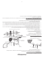
PUMP PRESSURE ADJUSTMENT
• If model is not equipped with a built in air pressure gauge, remove
pressure gauge plug from end of lter cover.
• If model is not equipped with a built in air pressure gauge, install
accessory pressure gauge.
• Start heater.
• Allow motor to reach full speed.
• Adjust pressure.
• Turn relief valve clockwise to increase pressure.
• Turn relief valve counterclockwise to decrease pressure.
• Set pump pressure to correct pressure for each model.
• Stop heater. If accessory pressure gauge is being used, remove
pressure gauge.
• Replace pressure gauge, and plug in end of lter cover. NOTE: USE
ONLY ORIGINAL EQUIPMENT REPLACEMENT PARTS. Use of alternate
or third party components will void warranty and may cause an
unsafe operating condition.
Pressure
Gauge
Plug
Relief
Valve
Adjusting Pump Pressure
NM-75K
Adjusting Pump Pressure
NM-125K, NM-175K, NM-215K
Maintenance
Photocell
Photocell
lens
Install Photocell
1) Incorrect
2) Correct
Photo Cell Wire
Circuit
Board
Side Cover
Power Switch
Power Switch Wire
Screw
Fuel Filter
Fuel Line
Model Pump Pressure
NM-75K 4.7PSI
NM-125K 4.9PSI
NM-175K 4.9PSI
NM-215K 5.5PSI
Switch Wires
Circuit Board

-13-
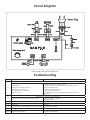
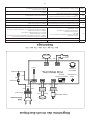
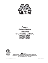
Power Plug
NM-75K, NM-125K, NM-175K, NM-215K
Circuit Diagram
Troubleshooting
Possible Cause Corrective Action
E1
Photocell (Flame Color Checking Sensor) Error
Oil Shortage
Bad Photocell (Flame Sensor)
Incomplete Combustion
Contamination of Fuel Filter
Ignition Failure
Charge Fuel (Fill the fuel if needed)
Check and clean or replace Photocell (Flame Sensor)
Using Designated Fuel
Clean or replace Fuel Filter
Check Wire Connection
Check Spark Plug For Normal Firing (clean or replace if
needed)
E2
Temperature sensor (Thermister) Error
Bad Connection or mis-operation of Sensor
Checking Wire Connection
Replace Sensor
LO Below 1°F Normal
HI Over 99°F Normal
OH It stops when the temperature reaches to 140°F Restart After Cooling
CN Continuously operating without set-temperature Normal
Blinking Error during operation
Check Error Code
Restart after resetting

-14-
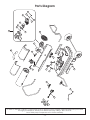
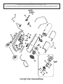
1
3
2
4
8
9
23
24
10
5
6
7
12
11
13
14
19
17
16
18
15
20
21
22
25
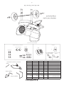
Parts Diagram
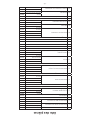
In order to maintain warranty, components must be replaced using original manufacturers parts purchased
through your dealer or directly from NewmacPro by calling 1-800-750-2723.
Use of third party components will void the warranty.

-15-
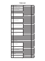
Parts List
Key Description Model Part No
1 Fuel Gauge Assembly
NM-75k
892822
NM-125K, NM-175K, NM-215K
892823
2 Fuel Filter Assembly
NM-75k
892824
NM-125K, NM-175K, NM-215K
892825
3 Fuel Cap Assembly 892826
4 Power Switch 80718
5 Air Line
NM-75k
892813
NM-125K
892814
NM-175K, NM-215K
892815
6 Thermostat Limit Control 80719
7 Photocell 81274
8 Nozzle Assembly
NM-75k
892827
NM-125K
892828
NM-175K
892829
NM-215K
892830
9 Spark Plug 80729
10 Motor and Pump Assembly
NM-75k
80742
NM-125K
80743
NM-175K
80744
NM-215K
80745
11 Insert 83758
12 Rotor
NM-175K
80720
NM-215K
80721
NM-75K, NM-125K
80722
13 Blade (four)
NM-175K
80723
NM-215K
80724
NM-75K, NM-125K
80725
14 Filter Kit Assembly 892831
15 End Filter Cover 892816
16 Ball 83760
17 Spring 83761
18 Adjust Screw 83762
19 Plug/Pump Kit 83759
20 Fan Assembly
NM-75k
80746
NM-125K
80747
NM-175K
80748
NM-215K
80749
21 Igniter
NM-125K
80726
NM-75K, NM-175K, NM-215K
80727
22 Fan Guard (Plastic)
NM-75k
892817
NM-125K, NM-175K, NM-215K
892818
23 Main P.C.B Assembly 80728
24 Thermistor 81275
25 Handle
NM-75k
892819
NM-125K, NM-175K, NM-215K
N/A
26 Guard, Canada (not shown)
NM-75k
892844
NM-125K, NM-215K
892845

-16-
LIMITEDWARRANTY
UnitedSta te sStoveCompanywarrantsthisproduct,totheoriginalretailpurchaseronly,tobefreefrom
defectsinmaterialandworkmanshipforaperiodofone(1)yearfromthedateoftheinitialpurchaseas
evidenced on an invoice, cancelled check, sales receipt, etc. In the event of a defect, this Limited
Warrantyshallbelimitedtothe repairorreplacementofparts,whichprovedefectiveundernormaluse
and service within the limited warranty period, and which United States Stove Company deems at its
reasonable discretion. THE LIMITED WARRANTY SET FORTH HEREIN IS THE SOLE WARRANTY
PROVIDED TO PURCHASER AND IS IN LIEU OF ALL OTHER WARRANTIES AND REPRESENTATIONS,
EXPRESS OR IMPLIED. UNITED STATES STOVE COMPANY MAKES NO REPRESENTATIONS OR
WARRANTIESWHATSOEVER,EXPRESSORIMPLIED,WITHRESPECTTOTHEPRODUCT,OTHERTHAN(i)
THELIMITE D WARRANTY ABOVE, AND(ii)ANY IMPLIEDWARRANTIES IMPOSEDBYAPPLICABLELAW
WHICH CANNOT BEWAIVED OR DISCLAIMEDUNDERAPPLICABLE LAW.ALL OTHER WARRANTIESOF
ANY KIND, INCLUDING WITHOUT LIMITATION IMPLIED WARRANTIES OF MERCHANTABILITY AND
FITNESS FOR A PARTICULAR PURPOSE, ARE HEREBY DISCLAIME D AND EXCLUDED TO THE FULLEST
EXTENTNOTPROHIBITEDBYAPPLICABLELAW.ThisLimitedWarrantygivesthepurchaserspecificlegal
rights;
apurchasermayhaveotherrightsdependinguponwhereheorsheresides.Somestatesdonot
allowtheexclusionorlimitationofspecial,incidentalorconsequential damages,orstatelawmayaffect
thedurationoflimitations,sotheaboveexclusiona nd limitationsmaynotbeapplicable.
OTHERLIMITATIONS:UnitedStatesSt oveCompanydisclaimsall otherwarrantiesforproductsthatare
purchased from sellers other than aut horized retailers or distributors. This product must be properly
installed, maintained and operated in accordance with the instructions provided herein. Furthermore,
United States S to v e Company requires reasonable proof of the date of purchase from an authorized
retailerordistributor.ThisLimited Warrantydoesnotcover any operation a l failures or difficulties due
to normal use and wear and tear, accident, abuse, misuse, alteration, misapplication, improper
installationorimpropermaintenanceorservicebyyouoranythirdparty.Failuretoperformnormaland
routinemaintenanceontheproduct,shippingdamage,damagerelatedtoanimals,anddamagedueto
weatherarenotcoveredunderthisLimitedWarranty.Inaddition, thisLimitedWarrantydoesnotcover
damage to the finish on the product, such as scratches, den ts, discoloration, rust or other weather
damage. This warranty does not
apply to products purchased for rental use.United States Stove
Company assumes no responsibility for any defects caused by third parties. United States S tove
Companydoesnotauthorizeanypersonorcompanytoassumeforitanyo therobligationorliabilityin
connectionwiththesale,installation,use,removal,return,orreplacementofitsproducts,andnosuch
representationsarebindingonUnitedStatesStoveCompany.
CLAIMPROCEDURE:Alltransportationcostsforthereturnofthedamagedproductorpartswillbethe
responsibilityofthepurchaser.Uponreceiptoftheproduct, UnitedStatesStoveCompanywillexamine
it and determine if the product contains a defect. United States Stove Company will repair or replace
and return the item, freight pre‐paid. If United States Stove Company finds the item to be in normal
operating condition, or not defective, th e item will be returned freight co ll ect. Purchaser shall specify
themodelnumber(s)andserialnumber(s)ofanyproduct(s)whenmakinganyclaims withUnitedStates
StoveCompany.Pleaseusethefollowingtoidentifyyourproduct:
Model#:____________________
Serial#:_____________________

-16-
GARANTIE LIMITÉE
L’entreprise United States Stove Company garantit ce produit, seulement à l'acheteur commercial original,
d’être sans défaut matériel ou manutentionnaire pour une période d’un (1) an, à partir de la date d’achat
initiale, tel que convenu sur la facture, sur le chèque annulé sur le reçu de l’achat, etc. En cas de défaut, cette
garantie limitée est limitée à la réparation ou au remplacement des pièces qui se prouvées défectueuses selon
l’usage normal et le service normal, convenu à l’intérieur de la garantie limitée, et qui est jugé convenable à
la discrétion de l’United States Stove Company. LA GARANTIE LIMITÉE DÉNOTÉE CI-JOINT EST LA SEULE GARANTIE
FOURNIE À L'ACHETEUR ET EST EN LIEU DE TOUT AUTRE GARANTIE OU REPRÉSENTATION, EXPRESSE OU IMPLICITE.
L’UNITED STATES STOVE COMPANY NE FAIT AUCUNE REPRÉSENTATION OU GARANTIE QUE CE SOIT, QU’ELLE SOIT
IMPLICITE OU EXPRESSE, EN RESPECT AU PRODUIT, AUTRE QUE (i) LA GARANTIE LIMITÉE MENTIONNÉE CI-DESSUS, ET
(ii) TOUTE GARANTIE IMPLICITE IMPOSÉE PAR LA LOI APPLICATION QUI NE PEUT ÊTRE ANNULÉE OU DÉCLINÉES SELON
LA LOI APPLICABLE. TOUTE AUTRE GARANTIE, DE TOUT GENRE, INCLUANT MAIS SANS S’Y LIMITER AUX GARANTIES
IMPLICITES DE QUALITÉ MARCHANDE OU D’APTITUDE POUR UN BUT PARTICULIER, SONT DONC DÉCLINÉES ET
EXCLUSES AU PLUS HAUT POINT SELON LA LOI APPLICABLE. Cette garantie limitée donne à l'acheteur des droits
légaux spécifiques; un acheteur pourrait avoir des droits différents selon son lieu de résidence. Certains états
ne permettent pas l'exclusion ou la limitation de dommages spécifiques, accessoires ou consécutifs, ou des lois
d’état qui peuvent affecter la durée des limitations; l’exclusion et les limitations précédentes pourraient ne pas
s’appliquer.
AUTRES LIMITATIONS: L’United States Stove Company décline toutes autres garanties pour les produits qui sont
achetés auprès d’autres vendeurs que ceux autorisés. Ce produit doit être proprement installé, entretenu et
doit fonctionner selon les instructions ci-jointes. De plus, l’United States Stove Company requiert une preuve
raisonnable de la date d'achat effectuée auprès du fournisseur ou du distributeur autorisé. Cette garantie limitée
ne couvre pas les échecs ou les difficultés opérationnelles dus à un usage régulier et à l’usure, aux accidents, aux
abus, à l’abus, aux altérations, à l’installation ou à l’entretien incorrects effectués par vous ou par une troisième
partie. Un échec d’effectuer l’entretien normal et routinier de ce produit, les dommages d’expédition, les
dommages effectués par des animaux, et ceux faits par les événements météorologiques ne sont pas couverts
dans cette garantie limitée. Également, cette garantie limitée ne couvre pas le dommage fait au fini de ce
produit, comme les égratignures, les bosses, la discoloration du produit, la rouille ou tout autres dommages faits
par les événements météorologiques. Cette garantie ne s’applique pas aux produits achetés pour la location.
L’United Stated Stove Company n’assume aucune responsabilité envers les défauts effectués par des troisièmes
parties. L’United States Stove Company n’autorise aucune personne ou aucune entreprise d’assumer pour elle-
même toute obligation ou toute forme de responsabilité pour la vente, l’installation, l’utilisateur, l’enlèvement, le
retour ou le remplacement de ses produits, et aucune de ces représentations ne permette de lier l’United States
Stove Company.
PROCÉDURE DE RÉCLAMATION: Tous les coûts de transport pour le retour d’un produit ou de pièces endommagés
seront de la responsabilité de l'acheteur. Au moment de la réception du produit, l’United States Stove Company
examinera et déterminera si le produit est défectueux ou non. L’United States Stove Company réparera ou
remplacement et retournera le produit, par transport prépayé. Si United States Stove Company trouve que le
produit fonctionne selon les normes de fonctionnement normales, et qu’il n'est pas défectueux, le produit sera
retourné par port dû. Les acheteurs devront spécifier le numéro du mpdèle et le numéro de série de tout produit
lorsqu’ils feront les réclamations auprès d’United States Stove Company. Veuillez fournir les informations suivantes
afin d’identifier votre produit:
Modèle ____________________
No de série: _____________________

-15-
Liste des pièces
Clé Description Marquette Partie N°
1 Ensemble de jauge de carburant
NM-75k
892822
NM-125K, NM-175K, NM-215K
892823
2 Ensemble de filtre à carburant
NM-75k
892824
NM-125K, NM-175K, NM-215K
892825
3 Ensemble de bouchon de carburant 892826
4 Interrupteur 80718
5 Compagnie aérienne
NM-75k
892813
NM-125K
892814
NM-175K, NM-215K
892815
6 Contrôle de limite de thermostat 80719
7 Photocellule 81274
8 Ensemble de buse
NM-75k
892827
NM-125K
892828
NM-175K
892829
NM-215K
892830
9 Bougie d'allumage 80729
10 Ensemble moteur et pompe
NM-75k
80742
NM-125K
80743
NM-175K
80744
NM-215K
80745
11 Insérer 83758
12 Rotor
NM-175K
80720
NM-215K
80721
NM-75K, NM-125K
80722
13 Lame (quatre)
NM-175K
80723
NM-215K
80724
NM-75K, NM-125K
80725
14 Ensemble du kit de filtration 892831
15 Couvercle de filtre de fin 892816
16 Ballon 83760
17 Printemps 83761
18 Ajuster la vis 83762
19 Kit Plug / Pump 83759
20 Ensemble de ventilateur
NM-75k
80746
NM-125K
80747
NM-175K
80748
NM-215K
80749
21 Allumeur
NM-125K
80726
NM-75K, NM-175K, NM-215K
80727
22 Fan Guard (plastique)
NM-75k
892817
NM-125K, NM-175K, NM-215K
892818
23 Ensemble principal P.C.B 80728
24 Thermistance 81275
25 Manipuler
NM-75k
892819
NM-125K, NM-175K, NM-215K
N/A
26 Garde, Canada (non représenté)
NM-75k
892844
NM-125K, NM-215K
892845

-14-
1
3
2
4
8
9
23
24
10
5
6
7
12
11
13
14
19
17
16
18
15
20
21
22
25
Diagramme des pièces
Afin de maintenir la garantie, les composants doivent être remplacés à l’aide des pièces originales du
fabricant achetées via votre revendeur ou directement auprès de NewmacPro en composant le 1-800-750-
2723. L’utilisation de composants tiers annulera la garantie.

-13-
NM-75K, NM-125K, NM-175K, NM-215K
Bougie d’allumage
Noir
Noir
Amorceur
Brun
Brun
Température ambiante.
Achage
Lampe
de combustion
TEMP. Cadran
de contrôle
Condensateur
Rouge Jaune
Pompe du
moteur
Noir
Bleu
Brun Bleu
Alimentation
Câble
d'alimentation
Jaune
/vert
Bleu
Interrupteur
Bleu
Thermostat
Fusible
NoirNoirNoirNoir
Cellule
photoélectrique
Thermistor
PCB PRINCIPAL
Diagramme des circuits électriques
Dépannage
Cause possible Résolution de problème
E1
Erreur de cellule photoélectrique (détecteur de couleur de flamme)
Pénurie de pétrole
Mauvaise cellule photoélectrique (détecteur de
flamme)
Combustion incomplète
Contamination du filtre de carburant
Échec d’allumage
Changez le carburant (remplissez le radiateur si nécessaire)
Vérifiez et nettoyez la cellule photoélectrique (détecteur de flamme)
Utiliser le carburant désigné
Nettoyez ou remplacez le filtre à carburant
Vérifiez la connexion des câbles
Vérifiez la bougie d’allumage pour un allumage régulier (nettoyez-le
ou remplacez-le si nécessaire)
E2
Erreur de détecteur de la température (thermistor)
Mauvaise connexion ou mauvais fonctionnement du
détecteur.
Vérifiez la connexion des câbles
Remplacez le détecteur
LO Sous 1°F Normal
HI Au-dessus de 99 °F Normal
OH
Le radiateur s'arrête lorsque la température atteint
140 °F
Redémarrez après le refroidissement
CN
Opération continue sans température
préprogrammée.
Normal
Clignote Erreur durant le fonctionnement
Vérifiez le code d’erreur
Redémarrez après la réinitialisation
La page est en cours de chargement...
La page est en cours de chargement...
La page est en cours de chargement...
La page est en cours de chargement...
La page est en cours de chargement...
La page est en cours de chargement...
La page est en cours de chargement...
La page est en cours de chargement...
La page est en cours de chargement...
La page est en cours de chargement...
La page est en cours de chargement...
La page est en cours de chargement...
-
 1
1
-
 2
2
-
 3
3
-
 4
4
-
 5
5
-
 6
6
-
 7
7
-
 8
8
-
 9
9
-
 10
10
-
 11
11
-
 12
12
-
 13
13
-
 14
14
-
 15
15
-
 16
16
-
 17
17
-
 18
18
-
 19
19
-
 20
20
-
 21
21
-
 22
22
-
 23
23
-
 24
24
-
 25
25
-
 26
26
-
 27
27
-
 28
28
-
 29
29
-
 30
30
-
 31
31
-
 32
32


NewMac NM-175K Operating Instructions Manual
- Catégorie
- Cheminées
- Taper
- Operating Instructions Manual
dans d''autres langues
- English: NewMac NM-175K
Autres documents
-
 Mi-T-M MH-0400-0M10 Manuel utilisateur
-
 Mi-T-M MH-0600-0M10 Kerosene Portable Heater Le manuel du propriétaire
-
Mi-T-M MH-0125-0M10 Manuel utilisateur
-
 Mi-T-M MH-0400-0M10 Kerosene Portable Heater Le manuel du propriétaire
-
 L.B. White CP170AK Owner's Manual And Instructions
-
 L.B. White CP400AK Owner's Manual And Instructions
-
 Heat Stream HS-215T-KFA Mode d'emploi
-
 Mi-T-M Propane Directional Heater Le manuel du propriétaire
-
Warm Tech WTCAC30R-DU Le manuel du propriétaire
-
DeWalt DXH75KTHC Mode d'emploi


