Signat Furu 600 Le manuel du propriétaire
- Catégorie
- Amplificateur d'instruments de musique
- Taper
- Le manuel du propriétaire

1
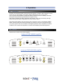
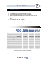
2 x 65 W
2 x 100 W
4 x 65 W
4 x 100 W

2
2 x 65 WATT
S
RM
S
2 x 100 WATTS RMS
4 x 65 WATTS RMS
4 x 100 WATTS RMS

3
Index
English
Page
1. Features
1.1 General features 4
1.2 Specifications 4
2. Installation
2.1 Note 5
2.2 Installation location 5
2.3 Mounting 5
3. Connection
3.1 Voltage and polarity 6
3.2 Fuses 6
3.3 Cabling – general instructions 6
3.4 Power supply connections 7
3.5 Signal connection 7
3.6 Speaker connection 9
4. Operation
4.1 Instructions 11
4.2 Controls 11
4.3 Description of features and controls 12
4.4 Troubleshooting 14
Deutsch
Seite
1. Technische Daten
1.1 Allgemeine Eigenschaften 15
1.2 Technische Daten 15
2. Montage
2.1 Hinweis 16
2.2 Einbauort 16
2.3 Befestigung 16
3. Anschluss
3.1 Spannung und Polarität 17
3.2 Sicherungen 17
3.3 Verkabelung – Allgemeine Hinweise 17
3.4 Stromversorgungsanschlüsse 18
3.5 Signalanschluss 18
3.6 Lautsprecheranschluss 20
4. Betrieb
4.1 Hinweise 22
4.2 Bedienungselemente 22
4.3 Bezeichnung der Kontroll- und Bedienungselemente 23
4.4 Problemlösungen 26
Français
Page
1. Caractéristiques
1.1 Caractéristiques générales 27
1.2 Spécifications 27
2. Installation
2.1 Note 28
2.2 Emplacement 28
2.3 Montage 28
3. Connexions
3.1 Tension et polarité 29
3.2 Fusibles 29
3.3 Câblage – Indications générales 29
3.4 Câblage d’alimentation 30
3.5 Connexion du signal 30
3.6 Connexion des haut-parleurs 32
4. Utilisation
4.1 Indications 34
4.2 Contrôles 34
4.3 Explication des caractéristiques et contrôles 35
4.4 En cas de difficulté 38

4
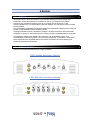
1 Features
1.1 General features
¾ Double sided, glass fibered epoxy PC board, through hole mounted
¾ RCA jacks, speaker and power terminals
¾ 2 Ohm stability
¾ Turn-on delay, turn-off muting
¾ Protection circuitry against thermal and electrical overload, short circuit, DC-offset
¾ BIC, balanced input circuitry, with floating ground technology for maximum noise
reduction
¾ Blue illuminated FURY Lion’s head
¾ Protection indicator
¾ Power supply +12 V DC, negative ground
¾ ENS Electronic Noise Suppression
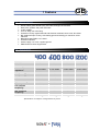
1.2 Specifications
Channels
2 2 4 4
BIC - ENS
Yes Yes Yes Yes
Maximum power
400W 600W 800W 1200W
Minimum speaker
impedance
2 ohm stable 2 ohm stable 2 ohm stable 2 ohm stable
RMS power @4 Ohms
65W x 2 100W x 2 65W x 4 100W x 4
RMS power @2 Ohms
100W x 2 150W x 2 100W x 4 150W x 4
Fuse
25A x 1 25A x 1 25A x 2 25A x 2
S/N ratio
90dB 90dB 90dB 90dB
Input sensitivity
150m~4V 150m~4V 150m~4V 150m~4V
Input impedance
25KOhm 25KOhm 25KOhm 25KOhm
50~250 Hz 50~250 Hz 50~250 Hz 50~250 Hz
LPF (lowpass
frequency)
12dB/oct. 12dB/oct. 12dB/oct. 12dB/oct.
50~250 Hz 50~250 Hz 50~250 Hz 50~250 Hz
HPF (highpass
frequency)
12dB/oct. 12dB/oct. 12dB/oct. 12dB/oct.
Bass boost
0-12dB @50Hz 0-12dB @50Hz 12dB @50Hz 12dB @50Hz
Specifications are subject to change without any notice.
GB

5
2 Installation
2.1 Note
Before commencing the installation work, please first plan the complete installation, taking
into account the cable layout and the installation of the equipment.
We recommend handing over the installation work to a specialist installer. Evidence of
technically correct installation and connection of the equipment is a pre-condition for the
provision of guarantee services by SIGNAT, should a defect occur.
WARNING:
Disconnect the negative (-) battery cable before mounting the amplifier or before making any
connections
2.2 Installation location
Choose a mounting location for your amplifier. Find a location on a flat surface away from
heat and moisture; please ensure that there is sufficient room for movement when laying the
cable connections and for operating and inspecting the adjustment devices and control
switches. Be sure the mounting location and the drilling of pilot holes for mounting will not
present a hazard to any wires, control cables, fuel lines, fuel tanks, hydraulic lines, or other
vehicle systems or components (Attention: components of this type may also be hidden in
double-walled linings!).
Common mounting locations are under the front passenger seat, or in the trunk area. Choose
a location with unimpaired air circulation. The amplifier will dissipate heat more efficiently if
mounted vertically.
2.3 Mounting
The amplifier must be professionally attached in the interest of safety. The chosen location
must be suitable for taking the screws and offer sufficient support.
Use the enclosed screws. Place the amplifier at the mounting location, and mark the positions
of the holes with a marker, pen or pencil. Using a 2.5mm bit, carefully drill the mounting holes
in the marked positions.
Check carefully before drilling any pilot holes.
Use the supplied mounting screws to securely fasten the amplifier to the mounting surface.

6
3 Connection
3.1 Voltage and polarity
SIGNAT amplifiers can only be installed in vehicles in which the 12-volt negative terminal is
grounded. If the amplifier is connected to other systems, the electrical system of the car and
the amplifier can be damaged.
3.2 Fuses
Fuses in the amplifier should never be bridged or replaced by fuses with a higher rating. This
also applies to fuses in the supply system close to the battery. Both the amplifier and the
electrical system of the vehicle can be completely destroyed by operation with incorrect or
bridged fuses.
3.3 Cabling - general instructions
WARNING:
Disconnect the negative (-) battery cable before making any connections.
All cable connections must be laid without risk of pinching, squeezing or breaking in a way
they can be inspected and handled without problems in the area of the corresponding
equipment connection components. Sharp corners and edges must be protected against
abrasion by abrasion-resistant padding. Plastic hoses and feed-through grommets may also
be used here.
Cables should never be laid alongside electrical or other supply lines to items of car
equipment or in the immediate neighborhood of such equipment (fan motors, fire control
module, and fuel lines). Moreover, cross-talk interference occurs in the audio system if audio
cables are laid alongside other electrical cables, which can drastically reduce the pleasure of
listening.
In general, care should be taken that all connection materials used are of high quality and
easy to handle.
All bright selections of wire must be permanently insulated. The cable cross-sections must be
appropriate to the power requirement and the capacity of the SIGNAT Fury amplifier.
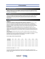
We recommend the following minimum cross-sections:
Power supply +12Volt and ground cable:
2 m 3 m 4 m 5 m 6 m 7 m 8 m 9 m
151-200 A
20 35 50 70 95 95 120 120
101-150 A
20 35 35 50 70 70 95 95
81-100 A
10 20 35 35 50 50 50 70
61-80 A
6 20 20 20 35 35 50 50
41-60 A
4 6 10 20 20 20 20 35
31-40 A
4 6 10 10 20 20 20 20
21-30 A
4 6 10 10 20 20 20 20
0-20 A
4 4 6 6 10 10 10 20
Remote-turn-on-cable: min. 1.5 mm²
An incorrect cable size (cross-section) will cause a poor sound quality; furthermore the
amplifier and the electrical system of the vehicle can be completely destroyed by using it with
incorrect cable size!

7
3.4 Power supply connections
3.4.1 Ground cable
The ground cable must be permanently connected to the metal of the vehicle chassis. During
the connection process, please ensure that the metal of the vehicle chassis is bright and free
from paint residues. Good grounding constitutes the basis for a high audio quality of the entire
system. The best solution is to connect the ground cables of all audio components (car radio,
amplifier, equalizer, etc.) to one common place of the vehicle's chassis. Connect the ground
cable to the screw terminal labeled „GND“.
3.4.2 +12V Power cable
Run a power cable from the battery to the amplifier; use appropriate cable size. You have to
install an additional fuse within 20 centimeters distance from the battery. Keep in mind that
the fuse also has to protect the vehicle against possible electrical fires caused by short
circuits. Inserting the fuse should be the last installation step in any system before initial
power up.
The +12V power cable must be directly connected to the positive terminal of the battery, not
to the electrical system of the car.
3.4.3 Remote-turn-on-cable
The remote-turn-on-cable is connected to the "Remote" connection or to the "Automatic
antenna" connection of the radio unit. The latter is only activated when the radio is switched
"ON". Therefore, the amplifier is switched off if remote is not activated and this saves the
battery.
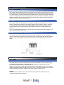
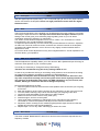
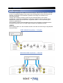
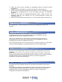
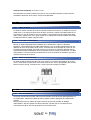
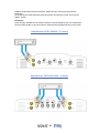
3.5 Signal Connection
3.5.1 Input
The inputs serve to connect to an audio source with preamp level outputs. Use heavy-duty
RCA patch cords designed for mobile applications.
Run the patch cables carefully, maintaining as much distance as possible from power,
speaker, and accessory wiring. Make sure the RCA plugs fit tightly for a secure connection.
SIGNAT amplifiers feature BIC (Balanced input circuitry). The input sensitivity of the amplifier
can be adjusted to the output voltage of your radio using the "GAIN" control.
Remark:
Please avoid any use with “open” (disconnected) input jacks; BIC requires a properly
connected input to the audio source.

8
FURY 400/600 amplifier – 2 channel
BASS
BO O ST
LPF
LPF
MIN
ENS
L
R
INPUT
MAX
FLAT
GAIN
HPF
HPF
150Hz
50Hz
6dB 12dB
OFF
250Hz
PWR/PRT
FURY 800/1200 amplifier – 4 channel
FILTER
BASS
BO O ST
BA SS
BO O ST
LPF
LPF
MIN
MIN
ENS ENS
CH 3
CH 1
CH 2
CH 4
MAX MAX
FLAT
FLAT
CH 1 / CH 2
CH 1/ CH 2
CH 3/ CH 4
CH 3 / CH 4
GAIN
GAIN
HPF
HPF
50Hz50Hz
OFF
OFF
ON
ON
250Hz
250Hz
POWER PROTECT

9
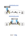
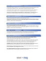
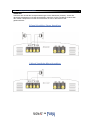
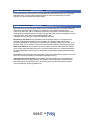
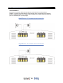
3.6 Speaker connection
WARNING:
Never connect the speaker leads to the vehicle chassis (ground).
Ensure that all the speakers are connected in phase, i. e. positive to positive and negative to
negative. With most speakers the positive connection is marked "positive" or with a dot.
2-channel FURY amplifier stereo
BRIDGE
LEFT
RICHT
2-channel FURY amplifier mono
BRIDGE
LEFT
RICHT

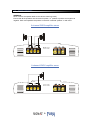
10
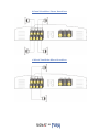
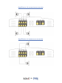
4-channel FURY amplifier stereo
+12V
CH 4
CH 3
CH 1
CH 2
REM GND
BRIDGE
4-channel FURY amplifier mono
+12V
CH 4 CH 3
CH 1CH 2
REM
GND
BRIDGE

11
4 Operation
4.1 Instructions
Recheck all connections before reconnecting the negative (-) battery cable. Insert the correct
value fuse in the fuse holder at the battery before attempting to turn on the system.
Any car system using SIGNAT components takes its power from the car battery. Therefore
the system should only be operated with the engine running.
High power amplifiers are able to generate sound levels, which can permanently damage
human hearing. We advise responsible use of the volume control.
We recommend handing over the mounting and connection work to an authorized SIGNAT
dealer. We also highly recommend consulting your dealer for the set-up and fine-tuning of
your audio system. The technical data of the applied speakers and the individual acoustical
conditions of the vehicle are important to consider when adjusting the audio equipment.
4.2 Controls
Features and controls of the FURY amplifier.
2-channel FURY 400/600 amplifier
BASS
BOOST
LPF
LPF
MIN
ENS
L
L
INPUT
MAX
FLAT
GAIN
HPF
HPF
150Hz
50Hz
6dB 12dB
OFF
250Hz
PWR/PRT
4-channel FURY 800/1200 amplifier
FILTER
BA SS
BO O ST
BA SS
BO O ST
LPF
LPF
MIN
MIN
ENS ENS
CH 3
CH 2
CH 1
CH 4
MAX MAX
FLAT
FLAT
CH 1/ CH 2
CH 1/ CH 2 CH 3/ CH 4
CH 3/ CH 4
GAIN GAIN
HPF
HPF
50Hz
50Hz
OFF
OFF
ON
ON
250Hz
250Hz
POWER
PROTECT

12
4.3 Description of features and controls
4.3.1 Line input - INPUT
With the signal input RCA jacks, left („L“ ch1 or ch3) and right („R“ ch2 or ch4) input channels
can be connected to the amplifier. Please use high performance audio cable like Signat
Platinum series!
4.3.2 Gain - GAIN
The input level (sensitivity) of the amplifier can be adjusted to the output voltage of your head
unit using the input level control. The input level control does not adjust volume! Optimum
setting of the control gives you a sufficiently large regulating zone for your car stereo
combination without any distortion or overloading.
The „GAIN“ control allows an adjustment from 4.0V to 150mV. Turn clockwise to increase
input sensitivity, turn counterclockwise to decrease.
To adjust the input sensitivity, turn the controls fully counterclockwise to minimum. Adjust the
car radio unit volume to maximum volume, and then turn the level controls on the amplifier
clockwise until audible distortion occurs. Now turn very slightly counterclockwise and the
adjustment is done.
An incorrect level control adjustment not only has a negative effect on "sound impression" but
can also destroy your speakers!
4.3.3 ENS noise suppression - ENS
The ENS adjustment capability allows you to fine-tune the BIC’s (Balanced Input Circuitry) for
maximum noise rejection of your car audio system.
It is usually not necessary to change the factory ENS setting.
Therefore we recommend using the factory setting of ENS as it is.
In case of any trouble with whining or and ticking noise problems, we recommend consulting
an experienced installation specialist for assistance in ENS adjustment.
CAUTION: the amplifier must be installed correctly, and connected to the source and
any other components normally used in the system. Never insert anything metallic into
any openings in the Amplifier side panels. For ENS adjustment, only use a small, non-
metallic, blade type screwdriver that will fit though the opening.
Recommended adjustment of ENS:
1. With the system turned off, disconnect the main speakers from the channel you are going
to fine tune
2. Mark the position(s) of the „GAIN“ control(s) for the channel(s) you are going to fine tune.
3. Turn the „GAIN“ control(s) fully CW for the channel(s) you are going to fine tune.
4. Connect a small test speaker to the channel you want to adjust.
5. Make sure the source unit volume is fully CCW (min).
6. Start the engine, and turn on the system
7. Use a small plastic screwdriver to adjust ENS for the channels the test speaker is
connected to. Listen to the speaker, and adjust for the minimum noise level.
8. Adjust the „GAIN“ control(s) to the marked (original) position again, disconnect the test
speaker and reconnect the original speaker(s).
9. Repeat steps 1 to 8 for any other channel(s) you wish to fine tune.
4.3.4 Bass boost - BASS BOOST
The switch marked ‘BASS BOOST’ allows for a reinforcement of the bass reproduction at a
frequency of 50Hz.

13
4.3.5 Filter - FILTER
If the FILTER switch is shifted to ‘LPF’, the input signal will pass the low pass crossover. If the
FILTER switch is shifted to ‘FLAT’, the signal will not pass the low pass crossover.
If the FILTER switch is shifted to ‘HPF’, the input signal will pass the high pass crossover. If
the FILTER switch is shifted to ‘FLAT’, the signal will not pass the low pass crossover.
When the input signal has been already filtered in an earlier stage (e.g. subwoofer output of
the head unit or another amplifier), this switch has to be shifted to the ‘FLAT’ position.
4.3.6 Highpass filter - HPF
Only the higher frequencies can pass, if a high pass filter is chose.
Move the FILTER switch into HPF position to use this filter. The crossover frequency (HPF) is
variable from 50 Hz to 250 Hz and can be individually adjusted. Turn CW to set to a higher
frequency, CCW to set to a lower frequency.
4.3.7 Lowpass filter - LPF
The low pass filter passes the deeper frequencies only.
Move the FILTER switch into LPF position to use this filter. The crossover frequency (LPF) is
variable from 50 Hz to 250 Hz and can be individually adjusted. Turn CW to set to a higher
frequency, CCW to set to a lower frequency.
4.3.8 Power indicator - PWR
The LED indicator at the side panel provides a visual indication of the switched on status of
the amplifier. If the LED indicator doesn’t light up, the amplifier has been shut off.
4.3.9 Protection - PROT
The LED protection indicator PROT provides a visual indication of an existing problem;
therefore the protection circuitry has protected the amplifier by shutting it down. Turn the
system off and correct the problem before turning the system back on.
Thermal protection: the amplifier will shut down if its temperature exceeds a safe operating
level. The amplifier will remain off until it is cooled down to a safe operating temperature.
Take care! The exterior of the amp may get too hot to touch before shutting down.
Overload: the amp will shut down if the electrical current demands exceed a safe level (this
can be caused by too low impedances or by an incorrect input level adjustment).
Short circuit: the amplifier will shut down due to a short circuit condition (this can be caused
by a poor insulation, by a damaged voice coil etc.)
D.C. offset protection: the amplifier will shut down due to an unsafe DC offset condition at
the amplifier output. Further damage of speakers will be avoided.

14
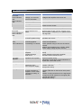
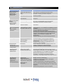
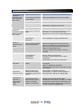
4.4 Troubleshooting
Condition Possible Cause Solution
Low or no remote turn on
voltage, or no remote
turn on connection
Check the remote turn on connection and the
voltage at the amplifier and source unit
Blown fuse(s) Check all system fuses
Wiring problems Recheck all connections
Check for short circuits
No sound
Power indicator
unlit
PROT indicator
unlit
Blown speakers Check speakers with another amplifier
Wrong alignment of
filters.
Double check all filter controls; possibly some
filter overlaps in frequency; if so, please correct
the alignment.
No sound
Power indicator lit
PROT indicator
unlit
Defect speaker or
incorrect speaker wiring
Double check function of speakers and wiring of
speakers and correct.
Amplifier shuts
down
PROT indicator lit
Protection circuit
protecting against
overheating or overload
Check for adequate ventilation
Check load impedance
Check speaker wiring for short to the vehicle
chassis
Reduce input sensitivity (turn „LEVEL“ CCW)
Check supply voltage at power terminal.
Distortion in sound Input level not properly
adjusted
Speaker damage
ENS control
Readjust amplifier input level (turn „LEVEL“
CCW)
Check speakers with another amplifier
Set ENS to reduce distortions to min.
Poor bass
response
Speakers out of phase Recheck speaker wiring
Subwoofer: check wiring; check adjustment of
phase shift control and correct.
Ticking noise Radiated noise from
spark plug wires
Poor car power supply
Reroute amplifier input wiring
Install a noise filter
Readjust ENS setting
Whining noise Alternator noise caused
by poor grounding of
amplifier, source, other
component, battery, or
alternator
Check all ground connections
Install a noise filter on the source unit’s power
cable
Install a coupling transformer in the signal path
to improve ground isolation for the signal path
(ground loop isolator)
Readjust ENS setting

15
1 Technische Daten
1.1 Allgemeine Eigenschaften
¾ Doppelseitig kaschierte, glasfaserverstärkte Epoxy-Leiterplatte, durchkontaktiert
¾ RCA-Buchsen, Lautsprecher- und Power Anschlüsse hartvergoldet
¾ 2 Ohm stabil (Stereo Mode und Mono-Kanal)
¾ Einschaltverzögerung, Ausschalt-Mute
¾ Dual-PWM (Puls-Weiten-Moduliertes) Schaltnetzteil, MOSFET Technologie
¾ Elektronische Schutz-und Überwachungskreise (thermische und elektrische Überlast,
Kurzschluss, DC-Offset)
¾ Optimierte Störunterdrückung durch BIC-Eingänge (Balanced Input Circuitry) mit
“Floating Ground Technik”
¾ Blaue FURY Löwenkopf Beleuchtung
¾ Störungsindikator “Protection”
¾ Betriebsspannungsversorgung +12V DC, Negative Masse (GND)
¾ ENS Elektronische Störunterdrückung
1.2 Technische Daten
Kanäle
2 2 4 4
BIC - ENS
Ja Ja Ja Ja
Maximalleistung
400W 600W 800W 1200W
Lautsprecher
Tiefstimpedanz
2 Ohm stabil 2 Ohm stabil 2 Ohm stabil 2 Ohm stabil
RMS Leistung @4Ohm
65W x 2. 100W x 2 65W x 4 100W x 4
RMS Leistung @2Ohm
100W x 2 150W x 2 100W x 4 150W x 4
Sicherung
25A x 1 25A x 1 25A x 2 25A x 2
S/N Ratio
90dB 90dB 90dB 90dB
Eingangsempfindlichk.
150m~4V 150m~4V 150m~4V 150m~4V
Eingangsimpedanz
25KOhm 25KOhm 25KOhm 25KOhm
50~250 Hz 50~250 Hz 50~250 Hz 50~250 Hz
LPF (Tiefpass Frequenz)
12dB/Okt. 12dB/Okt. 12dB/Okt. 12dB/Okt.
50~250 Hz 50~250 Hz 50~250 Hz 50~250 Hz
HPF (Hochpass
Frequenz)
12dB/Okt. 12dB/Okt. 12dB/Okt. 12dB/Okt.
Bass Boost
0-12dB @50Hz 0-12dB @50Hz 12dB @50Hz 12dB @50Hz
Spezifikationen und Änderungen ohne Gewähr
D

16
2 Montage
2.1 Hinweis
Bevor Sie mit der Montage beginnen, planen Sie zuerst den kompletten Einbau unter
Berücksichtigung der Kabelverläufe und der Installation des Gerätes.
Wir empfehlen Ihnen, die Montage einem SIGNAT - Einbauspezialisten zu überlassen. Der
Nachweis eines fachgerechten Einbaus und Anschlusses der Geräte ist Voraussetzung für
Garantieleistungen von SIGNAT, wenn ein Mangel auftreten sollte.
SICHERHEITSHINWEIS:
Vor Beginn der Installation unterbrechen Sie den Minusanschluss (-) der Autobatterie.
2.1 Einbauort
Wählen Sie einen geeigneten Einbauort für Ihren Verstärker. Bitte beachten Sie, dass die
Endstufe nur in trockene Bereiche, die keiner direkten Hitzeeinstrahlung ausgesetzt sind (z.B.
Sonneneinstrahlung oder neben Heizungsauslaß), eingebaut werden darf. Darüber hinaus
muss die für die Kühlung des Gerätes notwendige Luftzirkulation gewährleistet sein. Achten
Sie bei der Wahl des Montageortes auch auf genügend Bewegungsfreiheit zum Verlegen der
Kabelverbindungen und zum Bedienen sowie Einsehen der Einstellvorrichtungen und
Kontrollschalter.
Sehen Sie sich das Umfeld des gewählten Einbauortes genau an und vergewissern Sie sich,
daß keine Teile dahinter verborgen sind, wie etwa: elektrische Kabel und -Komponenten,
hydraulische Bremsleitungen oder Kraftstoffleitungen bzw. -tank. Diese könnten beim Bohren
der Befestigungslöcher beschädigt werden. Solche Teile können sich auch in der doppelten
Wandverkleidung verbergen!
Tip: Optimale Wärmeableitung ist gewährleistet, wenn die Endstufe mit den Kühlrippen
senkrecht montiert wird und ungehinderte Luftzirkulation gewährleistet ist.
2.2 Befestigung
Im Sinne der Unfallsicherheit muss die Endstufe professionell befestigt werden. Die
Montagefläche muss zur Aufnahme der Schrauben geeignet sein und genügend Halt bieten.
Benutzen Sie die beigefügten Schrauben. Stellen Sie das Gerät an den Montageplatz und
markieren Sie mit einem Filzstift die Stellen für die 4 Befestigungslöcher. Zum Bohren
verwenden Sie einen 2,5mm Bohrer.
Bevor Sie Bohren, versichern Sie sich nochmals keine verborgenen Teile zu beschädigen!
Stecken Sie nun die beigefügten Schrauben in die Bohrungen und ziehen diese gleichmäßig
an, bis das Gerät ordnungsgemäß und fest sitzt; eine im Sinne der Unfallsicherheit korrekte
Befestigung des Gerätes ist unumgänglich.

17
3 Anschluss
3.1 Spannung und Polarität
SIGNAT Amplifier sind Hochleistungs-Endstufen für den automotiven Einsatz. Sie können nur
in KFZ eingebaut werden, die den 12-Volt Minuspol an Masse haben. Wird das Gerät an
andere Systeme angeschlossen, können die elektrische Anlage des Autos und die Elektronik
der Endstufe beschädigt werden.
3.2 Sicherungen
Die Sicherungen der Endstufe dürfen niemals überbrückt oder durch Einsatz von
Sicherungen mit höherem Stromwert ersetzt werden. Das gilt auch für Sicherungen im
Zuleitungssystem nahe der Batterie. Sowohl die Endstufe als auch die elektrische Anlage des
KFZ können bei Betrieb mit falschen oder überbrückten Sicherungen völlig zerstört werden!
3.3 Verkabelung, allgemeine Hinweise
SICHERHEITSHINWEIS:
Um einen Kurzschluss während der Installation zu vermeiden, unterbrechen Sie vorher den
Minus-Anschluss der Autobatterie, bis die Endstufe montiert und vollständig angeschlossen
ist.
Alle Kabelverbindungen müssen ohne Klemm-, Quetsch- oder Bruchgefahr verlegt sein, um
mögliche Isolationsbeschädigungen zu vermeiden. Scharfe Ecken und Kanten müssen gegen
Durchscheuern durch scheuerfeste Polster entschärft werden. Hier können auch Kunststoff-
schläuche und/oder entsprechenden Durchführungsösen verwendet werden.
Kabel dürfen niemals neben elektrischen oder anderen Zuleitungen zu Vorrichtungen des
KFZ oder in unmittelbarer Nähe solcher Vorrichtungen verlegt werden (z.B. Lüftermotoren,
Brandkontroll-Module, Benzinleitungen). Außerdem entstehen im Audiosystem infolge der
Verlegung von Audiokabeln neben anderen elektrischen Leitungen Übersprechstörungen, die
den Hörgenus drastisch mindern.
Steht der Einbauort der Endstufe fest, kürzen Sie die Leitungen für die Stromversorgung,
sowie die Lautsprecherleitungen auf ein Minimum; dies garantiert höchste Audio-Qualität und
maximale Ausgangsleistung des Systems.
Insgesamt sollte auf hohe Qualität und sichere Handhabbarkeit aller verwendeter
Anschlussmaterialien geachtet werden. Alle blanken Drahtstellen müssen dauerhaft isoliert
sein.
Die Kabelquerschnitte müssen dem Leistungsbedarf und der Leistungsfähigkeit der SIGNAT
Fury Endstufen angepasst sein. Wir empfehlen folgende Mindestquerschnitte:
2 m 3 m 4 m 5 m 6 m 7 m 8 m 9 m
151-200 A 20 35 50 70 95 95 120 120
101-150 A 20 35 35 50 70 70 95 95
81-100 A 10 20 35 35 50 50 50 70
61-80 A 6 20 20 20 35 35 50 50
41-60 A 4 6 10 20 20 20 20 35
31-40 A 4 6 10 10 20 20 20 20
21-30 A 4 6 10 10 20 20 20 20
0-20 A 4 4 6 6 10 10 10 20

18
Remote-turn-on Kabel: mindestens 1,5 mm²
All zu niedrige Kabelquerschnitte trüben nicht nur die Audioqualität Ihres Systems und führen
zu einem drastischen Leistungsverlust; es besteht auch die Gefahr eines Kabelbrandes, die
Fahrzeugelektrik kann Schaden nehmen und die Elektronik der Endstufe kann zerstört
werden!
3.4 Stromversorgungsanschlüsse
3.4.1 Massekabel
Das Massekabel muss fest mit dem Metall des Kfz-Chassis verbunden werden. Achten Sie
beim Anschluss darauf, dass das Metall des Kfz-Chassis blank und frei von Lackresten ist,
um einen sicheren elektrischen Kontakt zu gewährleisten. Eine gute Erdung ist Grundlage für
die Tonqualität des gesamten Systems. Die ideale Lösung ist, die Masseanschlüsse aller
Audio-Komponenten (Radio, Endstufe, evt. Equalizer etc.) an einem gemeinsamen
Massepunkt des Kfz-Chassis zu verbinden. Die andere Seite des Massekabels muss an das
Power Terminal der Endstufe, Klemme „GND“ angeschlossen werden.
3.4.2 +12V Stromkabel
Setzen Sie die Kabelsicherung erst ein, wenn der Anschluss komplett fertiggestellt wurde!
Verwenden Sie ein Stromkabel entsprechenden Querschnitts mit Sicherungshalter. Der
Sicherungshalter ist unmittelbar an der Batterie zu plazieren. Verbinden Sie das kurze
Kabelende (max. 20 cm hinter Sicherungshalter) mit dem Plus-Pol der Batterie; das lange
Kabelende muss an das Power Terminal der Endstufe, Klemme „+12V“ angeschlossen
werden.
Das +12V Kabel direkt an den Pluspol der Batterie anschließen (nicht an
Sicherungsverteilung o.ä.)!
Der Wert der Kabelsicherung ist vom verwendeten Kabelquerschnitt abhängig und muss vom
Spezialisten bestimmt werden.
3.4.3 Remote-turn-on (Fernbedienungskabel)
Das Remote-turn-on Kabel wird mit dem "Remote"-Anschluss oder dem "Automatische-
Antenne"-Anschluss des Radiogerätes verbunden. Dieser ist nur aktiviert, wenn das Radio
EIN geschaltet ist. Somit wird die Endstufe bei nicht aktiviertem Remote ausgeschaltet und
die Batterie geschont.

19
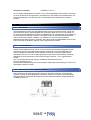
3.5 Signalanschluss
3.5.1 Signaleingang
Vorverstärker-Eingänge der Geräte sind mit hochwertigen, RCA Buchsen bestückt; verbinden
Sie die Vorverstärkerausgänge (Line-Output) Ihres Steuergerätes mit den RCA Buchsen der
Endstufe. Verwenden Sie ausschließlich qualitativ hochwertige Cinch-Kabel für den
automotiven Einsatz.
Verlegen Sie die Kabel vorsichtig; achten Sie auf maximale Distanz zu den Power-,
Lautsprecher- und anderen Stromkabeln im Fahrzeug. Stellen Sie sicher, dass die Cinch-
Kabelstecker korrekt in die RCA Buchsen eingesteckt werden, um einen dauerhaft guten
Kontakt zu gewährleisten.
Signat Modelle verfügen über BIC (Balanced Input Circuitry) Eingänge. Die Empfindlichkeit
der Signal-Inputs kann über die "GAIN"-Regler entsprechend angepasst werden.
HINWEIS:
BIC-Eingänge sollten nie „offen“ betrieben werden; bitte stets die Verbindung zur Signalquelle
aufrecht erhalten.
FURY 400/600 Verstärker – 2 Kanäle
FURY 800/1200 Verstärker – 4 Kanäle

20
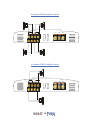
3.6 Lautsprecheranschluss
WARNUNG:
Verbinden Sie niemals die Lautsprecherleitungen mit der Kfz-Masse (Chassis). Achten Sie
darauf alle Lautsprecher in Phase anzuschließen, also Plus zu Plus und Minus zu Minus. Bei
den meisten Lautsprechern ist der Plus-Anschluss mit "Plus" oder einem Punkt
gekennzeichnet.
2-Kanal Verstärker Stereo Anschluss
2-Kanal Verstärker Mono Anschluss
La page est en cours de chargement...
La page est en cours de chargement...
La page est en cours de chargement...
La page est en cours de chargement...
La page est en cours de chargement...
La page est en cours de chargement...
La page est en cours de chargement...
La page est en cours de chargement...
La page est en cours de chargement...
La page est en cours de chargement...
La page est en cours de chargement...
La page est en cours de chargement...
La page est en cours de chargement...
La page est en cours de chargement...
La page est en cours de chargement...
La page est en cours de chargement...
La page est en cours de chargement...
La page est en cours de chargement...
La page est en cours de chargement...
La page est en cours de chargement...
-
 1
1
-
 2
2
-
 3
3
-
 4
4
-
 5
5
-
 6
6
-
 7
7
-
 8
8
-
 9
9
-
 10
10
-
 11
11
-
 12
12
-
 13
13
-
 14
14
-
 15
15
-
 16
16
-
 17
17
-
 18
18
-
 19
19
-
 20
20
-
 21
21
-
 22
22
-
 23
23
-
 24
24
-
 25
25
-
 26
26
-
 27
27
-
 28
28
-
 29
29
-
 30
30
-
 31
31
-
 32
32
-
 33
33
-
 34
34
-
 35
35
-
 36
36
-
 37
37
-
 38
38
-
 39
39
-
 40
40


Signat Furu 600 Le manuel du propriétaire
- Catégorie
- Amplificateur d'instruments de musique
- Taper
- Le manuel du propriétaire
dans d''autres langues
- English: Signat Furu 600 Owner's manual
- Deutsch: Signat Furu 600 Bedienungsanleitung
Autres documents
-
Bazooka ELA1500 Manuel utilisateur
-
 Phoenix Gold Z 1200W 5 Channel Amplifier Manuel utilisateur
-
Phoenix Gold SD800.5 Manuel utilisateur
-
Infinity KAPPA five Manuel utilisateur
-
MTX RT501 Le manuel du propriétaire
-
AXTON A470 Le manuel du propriétaire
-
MTX JH10001 Le manuel du propriétaire
-
JBL Stadium 5 Manuel utilisateur
-
Monacor WANTED-4/320 Manuel utilisateur
-
