Sony XM-1004GX Manuel utilisateur
- Catégorie
- Amplificateurs audio de voiture
- Taper
- Manuel utilisateur

1
SERVICE MANUAL
US Model
XM-1004GX
STEREO POWER AMPLIFIER
Other Specifications
Circuit system OTL (output transformerless) circuit
Pulse power supply
Inputs RCA pin jacks
High level input connector
Outputs Speaker terminals
Speaker impedance 2 – 8 Ω (stereo)
4 – 8 Ω (when used as a bridging amplifier)
Maximum outputs Four speakers: 170 W × 4 (at 4 Ω)
Three speakers: 170 W × 2 + 400 W × 1 (at 4 Ω)
Two speakers: 400 W × 2 (at 4 Ω)
Rated outputs (supply voltage at 14.4 V)
Four speakers:
75 W × 4 (20 Hz – 20 kHz, 0.04% THD, at 4 Ω)
100 W × 4 (20 Hz – 20 kHz, 0.1% THD, at 2 Ω)
Two speakers:
200 W × 2 (20 Hz – 20 kHz, 0.1% THD, at 4 Ω)
Frequency response 5 Hz – 50 kHz ( dB)
Harmonic distortion 0.005% or less (at 1 kHz, 4 Ω)
Input level adjustment range
0.2 – 6.0 V (RCA pin jacks)
0.4 – 12.0 V (High level input)
High-pass filter 50 – 300 Hz, –12 dB/oct
Low-pass filter 50 – 300 Hz, –12 dB/oct
Low boost 0 – 10 dB (40 Hz)
Phase shift adjustment range
0° – 180° (at 40 Hz)
Power requirements 12 V DC car battery
(negative ground)
Power supply voltage 10.5 – 16 V
Current drain at rated output : 40 A (4 Ω)
Remote input : 1.5 mA
Dimensions Approx. 358 × 50 × 264 mm
(w/h/d) (14
1/8 × 2 × 10 1/2 in.) not incl.
projecting parts and controls
Mass Approx. 3.5 kg (7 lb. 11 oz.) not incl. accessories
Supplied accessories Mounting screws (4)
Design and specifications are subject to change without
notice.
SPECIFICATIONS
AUDIO POWER SPECIFICATIONS
POWER OUTPUT AND TOTAL HARMONIC DISTORTION
75 watts per channel minimum continuous average power into
4 ohms, both channels driven from 20 Hz to 20 kHz with no more
than 0.04% total harmonic distortion per Car Audio Ad Hoc
Committee standards.
+0.5
–3
Notes on Chip Component Replacement
• Never reuse a disconnected chip component.
• Notice that the minus side of a tantalum capacitor may be
damaged by heat.
Ver 1.1 2001.05
Sony Corporation
e Vehicle Company
Shinagawa Tec Service Manual Production Group
9-873-520-11
2001E0400-1
© 2001.5
http://www.xiaoyu163.com
http://www.xiaoyu163.com

2
TABLE OF CONTENTS
1. GENERAL
Location and Function of Controls .......................................... 3
Connections ............................................................................. 4
2. DISASSEMBLY
2-1. Plate, Bottom ....................................................................... 6
2-2. AMP Board Section ............................................................. 6
2-3. AMP Board, Filter (A) Board, Filter (B) Board .................. 7
2-4. LED Board ........................................................................... 7
3. ELECTRICAL ADJUSTMENT ...................................... 8
4. DIAGRAMS
4-1. Block Diagram ..................................................................... 9
4-2. Printed Wiring Board –AMP Section– .............................. 11
4-3. Schematic Diagram –AMP Section (1/2)– ........................ 12
4-4. Schematic Diagram –AMP Section (2/2)– ........................ 13
4-5. Schematic Diagram –Filter (A), Filter (B),
LED Section– .................................................................... 14
4-6. Printed Wiring Boards –Filter (A), Filter (B),
LED Section– .................................................................... 15
5. EXPLODED VIEWS
5-1. Heat Sink (Main) Section .................................................. 17
5-2. AMP Board Section ........................................................... 18
6. ELECTRICAL PARTS LIST ........................................ 19
XM-1004GX
SAFETY-RELATED COMPONENT WARNING!!
COMPONENTS IDENTIFIED BY MARK 0 OR DOTTED LINE
WITH MARK 0 ON THE SCHEMATIC DIAGRAMS AND IN
THE PARTS LIST ARE CRITICAL TO SAFE OPERATION.
REPLACE THESE COMPONENTS WITH SONY PARTS WHOSE
PART NUMBERS APPEAR AS SHOWN IN THIS MANUAL OR
IN SUPPLEMENTS PUBLISHED BY SONY.
http://www.xiaoyu163.com
http://www.xiaoyu163.com

3
XM-1004GX
SECTION 1
GENERAL
This section is extracted
from instruction manual.
LEVEL
HPF
OFF
LPF
Phase shift
Normal
AMP
Powe r
Lch
LEVEL
HPF
OFF
LPF
Inverted
AMP
Powe r
Rch
BTL.
Lch
Rch
(BTL.)
FILTER
FILTER
LOW BOOST
LOW BOOST
TEST
TONE
Phase shift
10
10
0
40 100 1k
10
0
-10
-20
-30
-40
-50
-60
-70
-80
10 100 1k
HIGH PASS
50Hz
150Hz
300Hz
50Hz
LOW PASS
150Hz
300Hz
FILTER
LPF OFF HPF
LEVEL
LOW BOOST
(40Hz)
MIN MAX0dB +10dB
50Hz 300Hz
0˚ 180˚
PHASE
TEST
TONE
POWER/PROTECTOR
OVER CURRENTPOWER OFFSET THERMAL
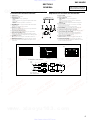
Location and Function of Controls
1 POWER indicator
Lights up in green during operation.
2 PROTECTOR indicator
• OVER CURRENT:
Lights up in red when receiving a powerful signal.
• OFFSET:
Lights up in red when the voltage going out to the Speaker terminal or the Pin
Jack is too high.
• THERMAL:
Lights up in red when the temperature rises to an unsafe level.
3 TEST-TONE button
When the button is pressed, operations of a built-in Oscillator allow the System
conditions to check.
Hearing the tones, the System is in good conditions.
4 FILTER selector switch
When the switch is in the LPF position, the filter is set to low-pass. When in the
HPF position, the filter is set to high-pass.
5 Cut-off frequency adjustment control
Sets the cut-off frequency (50–300 Hz) for the low-pass or high-pass filters.
6 PHASE SHIFT ADJUSTMENT control
Adjusting a phase shift for Subwoofer driving by using the knob, comes true a
controlled rich bass playback preventing by interference from Full range speakers.
7 LOW BOOST level control
Turn this control to boost the frequencies around 40 Hz to a maximum of 10
dB.
8 LEVEL adjustment control
The input level can be adjusted with this control when using source equipment
made by other manufacturers. Turn it to MAX when the output level of the car
audio seems low.
Emplacement et fonction des commandes
1 Indicateur POWER
S’allume en vert en cours fonctionnement.
2 Indicateur PROTECTOR
• OVER CURRENT:
S’allume en vert lors de la réception d’un signal puissant.
• OFFSET:
S’allume en rouge lorsque la tension de sortie vers le terminal du haut-
parleur ou la prise à broches est trop élevée.
• THERMAL:
S’allume en rouge lorsque la température atteint un niveau trop dangereux.
3 Touche TEST-TONE
Lorsque vous appuyez sur cette touche, la mise en marche d’un oscillateur
intégré permet de vérifier le système.
Si vous entendez le signal, le système est en bonne condition.
4 Sélecteur FILTER
Lorsque le commutateur est en position LPF, le filtre est mis sur passe-bas.
Lorsqu’il est en position HPF, le filtre est mis sur passe-haut.
5 Commandes de réglage de la fréquence de coupure
Règle la fréquence de coupure (50–300 Hz) des filtres passe-bas ou passe-haut.
6 Commande PHASE SHIFT ADJUSTMENT
Réglez le déphasage du Subwoofer à l’aide du bouton afin d’obtenir une
restitution fidèle des fréquences graves en évitant les interférences avec les
fréquences émises par les haut-parleurs principaux.
7 Commande de niveau LOW BOOST
Tournez cette commande pour amplifier les fréquences autour de 40 Hz à un
maximum de 10 dB.
8 Commande de réglage LEVEL
Le niveau d’entrée peut se régler avec cette commande lors de l’utilisation
d’équipements source d’autres fabricants. Mettez-le sur MAX lorsque le niveau
de sortie de l’installation audio paraît faible.
Circuit Diagram / Schéme du circuit
LOW BOOST
dB
FREQUENCY Hz
FREQUENCY Hz
dB
Cut-off frequency/Fréquence de coupure
20
0
-20
-40
-60
-80
-100
-120
-140
-160
10 100 1k 10k
-180
-200
0ß
180ß
Position of knobs
Position des boutons
FREQUENCY Hz
deg
PHASE SHIFT
Front :
Avant :
Rear : same as Front
Arrière : identique à l’avant
http://www.xiaoyu163.com
http://www.xiaoyu163.com

4
XM-1004GX
Cord diameter 0.3 – 1.25 mm (AWG 22 – 16)
Section du cordon : 0,3 – 1,25 mm (AWG 22 – 16)
Flat-head screwdriver
Tournevis à lame plate
11 (
7
/
16
)
Unit : mm (in.)
Unitè : mm (po.)
F
L
F
L
F
R
F
R
R
L
R
L
R
R
R
R
F
L
F
L
F
R
F
R
R
L
R
L
R
R
R
R
Speaker cord direct in connector
Cordon de haut-parleur directement dans le connecteur
*1
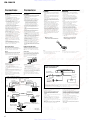
Connections Connexions
Attention
•
Avant d’effectuer les connexions, débranchez le
fil de masse de la borne de la batterie pour éviter
un court-circuit.
•
Utilisez des haut-parleurs d’une capacité
adéquate. Si vous utilisez des haut-parleurs de
faible capacité, ils risquent d’être endommagés.
•
Ne raccordez pas la borne # des haut-parleurs à
la carrosserie de la voiture ni la borne # du
haut-parleur droit à celle du haut-parleur
gauche.
•
Eloignez les cordons d’entrée et de sortie du fil
d’alimentation électrique pour éviter que des
interférences ne se produisent.
•
Cet appareil est un amplificateur de haute
puissance et il peut ne pas atteindre sa puissance
maximale si les cordons de haut-parleurs
originaux de la voiture lui sont raccordés.
•
Si votre voiture est équipée d’un ordinateur de
bord pour la navigation ou à toute autre fin, ne
débranchez pas le fil de masse de la batterie de la
voiture. Si vous débranchez ce fil, toute la
mémoire de l’ordinateur sera effacée. Pour éviter
un court-circuit lorsque vous effectuez
branchements, branchez le fil d’alimentation de
+12 volts uniquement après avoir branché tous
les autres fils.
Effectuez les connexions de la
manière indiquée ci-dessous.
Remarque
Ne serrez* pas trop fort la vis car vous pourriez l’endommager.
* Le couple de serrage devrait être inférieur à 1 N•m.
Caution
•
Before making any connections, disconnect the
ground terminal of the car battery to avoid short
circuits.
•
Be sure to use speakers with an adequate power
rating. If you use small capacity speakers, they
may be damaged.
•
Do not connect the # terminal of the speaker
system to the car chassis, and do not connect the
# terminal of the right speaker with that of the
left speaker.
•
Install the input and output cords away from the
power supply lead as running them close
together can generate some interference noise.
•
This unit is a high powered amplifier. Therefore,
it may not perform to its full potential if used
with the speaker cords supplied with the car.
•
If your car is equipped with a computer system
for navigation or some other purpose, do not
remove the ground wire from the car battery. If
you disconnect the wire, the computer memory
may be erased. To avoid short circuits when
making connections, disconnect the +12 V power
supply lead until all the other leads have been
connected.
Make the terminal
connections as illustrated below.
Note
Tighten the screws firmly, but be careful not to apply too much
force* as doing so may damage the screws.
* The torque value should be less than 1 N•m.
Power Connection Leads
Câbles d’alimentation
Car audio
Autoradio
Fuse (40 A)
Fusible (40 A)
+12 V car battery
Batterie de voiture +12 V
to a metal point
of the car
vers une partie
métallique de la
carrosserie
* If you have the factory original or some other car audio without a remote out-put on the amplifier, connect the remote input
terminal (REMOTE) to the accessory power supply.
* Si vous disposez du modèle d’origine ou d’un autre autoradio dont l’amplificateur ne comporte pas de sortie de télécommande,
raccordez la borne d’entrée de télécommande (REMOTE) à la prise d’alimentation accessoires.
Notes on the power supply
•
Connect the +12 V power supply lead only after all the other
leads have been connected.
•
Be sure to connect the ground lead of the unit
securely to a metal point of the car. A loose
connection may cause a malfunction of the
amplifier.
•
Be sure to connect the remote control lead of the car audio to
the remote terminal.
•
When using a car audio without a remote output on the
amplifier, connect the remote input terminal (REMOTE) to
the accessory power supply.
•
Use the power supply lead with a fuse attached (40 A).
•
Place the fuse in the power supply lead as close as possible to
the car battery.
•
Make sure that the leads to be connected to the +
12 V
and
GND
terminals of this unit are larger than 10-Gauge (AWG-
10) or have a sectional area of more than 5 mm
2
.
Remarques sur l’alimentation électrique
•
Raccordez le câble d’alimentation +12 V uniquement après
avoir réalisé toutes les autres connexions.
•
Raccordez correctement le fil de masse à une partie
métallique de la voiture. Une connexion lâche peut
provoquer un dysfonctionnement de l’amplificateur.
•
Veillez à raccorder le fil de télécommande de l’autoradio à la
borne de télécommande.
•
Si vous utilisez un autoradio dont l’amplificateur ne
comporte pas de sortie de télécommande, raccordez la borne
d’entrée de la télécommande (REMOTE) à la prise
d’alimentation accessoires.
•
Utilisez un câble d’alimentation muni d’un fusible (40 A).
•
Fixez le câble d’alimentation le plus près possible de la
batterie de voiture.
•
Vous devez raccorder des câbles de calibre supérieurs à 10
(AWG-10) ou d’une section supérieure à 5 mm
2
aux bornes
+12V
et
GND
.
Remote output*
Sortie de
télécommande*
(REM OUT)
Précautions
• Cet appareil est conçu pour fonctionner uniquement
sur courant continu de 12 volts avec masse négative.
• Utilisez des haut-parleurs d’une impédance
appropriée.
—
2 à 8
Ω
(stéréo).
• Ne raccordez pas de haut-parleurs actifs (avec
amplificateur intégré) aux bornes de haut-parleurs
de cet appareil; ils pourraient être endommagés.
• Evitez d’installer l’appareil à des endroits où:
—
il serait exposé à des températures élevées,
comme sous les rayons directs du soleil ou à
proximité d’une bouche d’air chaud
—
il serait exposé à la pluie ou à l’humidité
—
il serait exposé à la poussière ou à la saleté.
• Si votre voiture était garée en plein soleil et que la
température a considérablement augmenté à
l’intérieur, laissez refroidir l’appareil avant de
l’utiliser.
• Lorsque vous installez l’appareil à l’horizontale,
veillez à ne pas recouvrir la grille d’aération avec le
tapis, etc.
• Si cet appareil est trop près de l’autoradio, il est
possible qu’il y ait des interférences. Dans ce cas,
éloignez l’amplificateur de l’autoradio.
• Si l’appareil principal n’est pas alimenté, vérifiez les
connexions.
• Cet amplificateur est équipé d’un circuit* destiné à
protéger les transistors et les haut-parleurs en cas de
défaillance. N’essayez pas de tester l’efficacité de ce
circuit en recouvrant les dissipateurs thermiques ou
en effectuant des connexions inadéquates.
• N’utilisez pas l’appareil sur une batterie faible, car
sa performance maximale dépend d’une bonne
alimentation en électricité.
• Pour des raisons de sécurité, écoutez l’autoradio à
un volume modéré afin d’entendre les bruits
extérieurs.
• Les fonctions PHASE SHIFT permettant de réduire
les interférences de l’enceinte de plage totale et
d’extrêmes graves, les systèmes avec des enceintes à
plage totale utilisant HPF ne produisent pas un effet
suffisant.
Remplacement du fusible
Si le fusible saute, vérifiez les connexions du fil
d’alimentation et remplacez le fusible. S’il saute de
nouveau, un mauvais circuit interne peut en être la
cause. Dans ce cas, consultez votre concessionnaire
Sony.
Avertissement
En cas de remplacement du fusible, veillez à utiliser
un fusible dont l’intensité correspond à celle inscrite
sur le porte-fusible. N’utilisez jamais de fusible dont
l’intensité dépasse celle du fusible fourni avec
l’appareil, car vous risqueriez d’endommager
l’appareil.
*
Circuit
Cet amplificateur est équipé d’un circuit de protection qui
entre en service dans les cas suivants:
— surchauffe de l’appareil
— production d’un courant continu
— court-circuit aux bornes des haut-parleurs.
L’indicateur PROTECTOR s’allume en rouge et l’appareil
s’arrête.
Si le cas se présente, coupez l’alimentation de l’appareil
raccordé et éjecrez la cassette ou le disque compact avant
d’examiner la cause de la défaillance. Si l’amplificateur est
trop chaud, attendez qu’il refroidisse.
Pour toute question ou problème qui ne serait pas
traité dans ce manuel, consultez votre concessionaire
Sony.
Precautions
• This unit is designed for negative ground 12 V DC
operation only.
•
Use speakers with suitable impedance.
— 2 to 8 Ω (stereo).
• Do not connect any active speakers (with built-in
amplifiers) to the speaker terminals of the unit.
Doing so may damage the active speakers.
• Avoid installing the unit where:
—
it would be subject to high temperatures such as
from direct sunlight or hot air from the heater
—
it would be exposed to rain or moisture
—
it would be subject to dust or dirt.
• If your car is parked in direct sunlight and there is a
considerable rise in temperature inside the car,
allow the unit to cool down before use.
• When installing the unit horizontally, be sure not to
cover the fins with the floor carpet etc.
• If this unit is placed too close to the car radio,
interference may occur. In this case, relocate the
amplifier away from the car radio.
• If no power is being supplied to the master unit,
check the connections.
• This power amplifier employs a protection circuit*
to protect the transistors and speakers if the
amplifier malfunctions. Do not attempt to test the
protection circuits by covering the heat sink or
connecting improper loads.
• Do not use the unit on a weak battery as its
optimum performance depends on a good power
supply.
• For safety reasons, keep your car audio volume
moderate so that you can still hear sounds outside
your car.
• As PHASE SHIFT functions to reduce the
interference of the Full Range Speaker and Sub
Woofer, systems with Full Range Speakers using
HPF may not produce sufficient effect.
Fuse Replacement
If the fuse blows, check the power connection and
replace the fuse. If the fuse blows again after
replacement, there may be an internal malfunction. In
such a case, consult your nearest Sony dealer.
Warning
When replacing the fuse, be sure to use one matching
the amperage stated above the fuse holder. Never use
a fuse with an amperage rating exceeding the one
supplied with the unit as this could damage the unit.
*
Protection circuit
This amplifier is provided with a protection circuit that
operates in the following cases:
— when the unit is overheated
— when a DC current is generated
— when the speaker terminals are short circuited.
The PROTECTOR indicator lights up in red and the unit will
shut down.
If this happens, turn off the connected equipment, take out the
cassette tape or disc, and determine the cause of the
malfunction. If the amplifier has overheated, wait until the
unit cools down before use.
If you have any questions or problems concerning
your unit that are not covered in this manual, please
consult your nearest Sony dealer.
Car audio
Autoradio
White
Blanc
Gray
Gris
Black/White
Noir/Blanc
Black/Gray
Noir/Gris
Left speaker
Haut-parleur gauche
Right speaker
Haut-parleur droit
Car audio
Autoradio
Black-striped cord
Cordon rayé noir
Gray
Gris
White
Blanc
Black-striped cord
Cordon rayé noir
Green
Vert
Purple
Mauve
Left speaker
Haut-parleur gauche
Right speaker
Haut-parleur droit
Left speakera
Haut-parleur gauche
Right speaker
Haut-parleur droit
Front
Avant
Rear
Arrière
*2
http://www.xiaoyu163.com
http://www.xiaoyu163.com

5
XM-1004GX
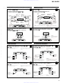
Input Connections
Connexions d’entrée
High Level Input Connection (with Speaker
Connection 1, 2 or 4)
Connexion à l’entrée de haut niveau (avec
connexion de haut-parleur 1, 2 ou 4)
AA
AA
A
4-Speaker System (with Input Connection A or C)
Système à 4 haut-parleurs (avec connexion d’entrée
A ou C)
Raccordement de haut-parleurs
Speaker Connections
11
11
1
3-Speaker System (with Input Connection A or C)
Système à 3 haut-parleurs (avec connexion
d’entrée A ou C)
22
22
2
Car audio
Autoradio
Front left speaker
output
Sortie de haut-
parleur avant
gauche
Rear left speaker
output
Sortie de haut-
parleur arrière
gauche
Input cord
(Not supplied)
Câble d’entrée
(Non fournis)
Input cord
(Not supplied)
Câble d’entrée
(Non fournis)
Rear right
speaker output
Sortie de haut-
parleur arrière
droit
Front right speaker
output
Sortie de haut-
parleur avant droit
High Level Input Connection (with Speaker
Connection 3)
Connexion à l’entrée de haut niveau (avec
connexion de haut-parleur 3)
BB
BB
B
Car audio
Autoradio
Right speaker output
Sortie de haut-
parleur droit
Left speaker output
Sortie de haut-
parleur gauche
Input cord
(Not supplied)
Câble d’entrée
(Non fournis)
Input cord
(Not supplied)
Câble d’entrée
(Non fournis)
Front speakers
(min. 2 Ω)
Haut-parleurs avant
(min. 2 Ω)
Left
Gauche
Right
Droit
Right
Droit
Left
Gauche
Rear speakers
(min. 2 Ω)
Haut-parleurs arrière
(min. 2 Ω)
Full range speakers
(min. 2 Ω)
Haut-parleurs pleine
gamme (min. 2 Ω)
Subwoofer
(min. 4 Ω)
Subwoofer
(min. 4 Ω)
Notes
•
In this system, the volume of the subwoofer will be
controlled by the car audio fader control.
•
In this system, the output signals to the subwoofer are a
combination of both the REAR L and R INPUT jacks or
the REAR high level input connector signals.
Remarques
•
Dans ce système, le volume du subwoofer est contrôlé par
le fader de l’autoradio.
•
Sur cet appareil, les signaux transmis vers le subwoofer
sont constitués des signaux des prises REAR L et R
INPUT.
2-Speaker System (with Input Connection B or D)
Système à 2 haut-parleurs (avec connexion d’entrée
B ou D)
33
33
3
2-Way System (with Input Connection A or C)
Système à 2 voies (avec connexion d’entrée
A ou C)
44
44
4
Left speaker
(min. 4 Ω)
Haut-parleur gauche
(min. 4 Ω)
Right speaker
(min. 4 Ω)
Haut-parleur droit
(min. 4 Ω)
Full range speakers
(min. 2 Ω)
Haut-parleurs pleine
gamme (min. 2 Ω)
Right
Droit
Left
Gauche
Right
Droit
Left
Gauche
Subwoofers
(min. 2 Ω)
Subwoofers
(min. 2 Ω)
Remarque
Assurez-vous que la sortie du haut-parleur droit de
l’autoradio est raccordée au connecteur portant l’indication
“REAR” sur l’appareil.
Note
Make sure that the right speaker output from the car audio
is connected to the connector marked “REAR” on the unit.
Striped
Rayé
Striped
Rayé
Pour plus de détails sur les réglages des commutateurs et
commandes, reportez-vous à “Emplacement et fonction des
commandes.”
For details on the settings of switches and controls, refer
to “Location and Function of Controls.”
Pour plus de détails sur les réglages des commutateurs et
commandes, reportez-vous à “Emplacement et fonction des
commandes.”
For details on the settings of switchesand controls, refer
to “Location and Function of Controls.”
Pour plus de détails sur les réglages des commutateurs et
commandes, reportez-vous à “Emplacement et fonction des
commandes.”
For details on the settings of switches and controls, refer
to “Location and Function of Controls.”
Pour plus de détails sur les réglages des commutateurs et
commandes, reportez-vous à “Emplacement et fonction des
commandes.”
For details on the settings of switches and controls, refer
to “Location and Function of Controls.”
Front Right e
Avant Droit e
Striped
Rayé
Striped
Rayé
Line Input Connection (with Speaker Connection
1, 2 or 4)
Connexion d’entrée de ligne (avec connexion de
haut-parleur 1, 2 ou 4)
CC
CC
C
Car audio
Autoradio
LINE OUT
Front
Avant
Rear
Arrière
Line Input Connection (with Speaker Connection 3)
Connexion d’entrée de ligne (avec connexion de
haut-parleur 3)
DD
DD
D
Car audio
Autoradio
LINE OUT
Left channel
Canal gauche
Right channel
Canal droit
Note
Make sure that the line output
from the car audio is connected to
the jack marked “L (BTL)” on the
unit.
Remarque
Dans ce système, le volume des subwoofers est contrôlé par le
fader de l’autoradio.
Note
In this system, the volume of the subwoofers will be
controlled by the car audio fader control.
Remarque
Vérifiez que la sortie de ligne de
l’autoradio est raccordée à la prise
portant l’indication “L (BTL)” sur
l’appareil.
BTL BTL BTL BTL
BTL BTL
*2 *2
*1
*1
Front Left e
Avant
Gauche e
Front Right E
Avant Droit E
Front Left E
Avant Gauche E
Rear Right e
Arrière Droit e
Rear Left e
Arrière
Gauche e
Rear Right E
Arrière Droit E
Rear Left E
Arrière Gauche E
Left
Gauche
Right
Droit
http://www.xiaoyu163.com
http://www.xiaoyu163.com

6
XM-1004GX
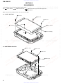
SECTION 2
DISASSEMBLY
• The equipment can be removed using the following procedure.
2-2. AMP BOARD SECTION
1
BTP 3x6
5
plate, bottom
7
sheet, insulating
6
2
BTP 3x6
3
BTP 3x6
4
P 2.6x2.8
5
CNP808
4
1
B.TT. 3x14
2
B.TT. 3x14
3
B.TT. 3x14
6
AMP board
Set Plate, Bottom
LED Board
AMP Board, Filter (A) Board, Filter (B) Board
AMP Board Section
Note : Follow the disassembly procedure in the numerical order given.
2-1. PLATE, BOTTOM
http://www.xiaoyu163.com
http://www.xiaoyu163.com

7
XM-1004GX
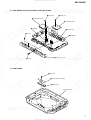
2-3. AMP BOARD, FILTER (A) BOARD, FILTER (B) BOARD
2-4. LED BOARD
1
BTP 3x6
2
sheet (LED), insulating
3
LED board
heat sink (main
)
1
P 3x8
2
P 3x8
5
CNP806
8
CNP807
7
BVTT 3x5
4
BVTT 3x5
6
FILTER (A) board
9
FILTER (B) board
0
AMP board
3
panel (4ch), front
http://www.xiaoyu163.com
http://www.xiaoyu163.com

XM-1004GX
8
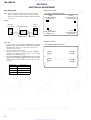
Bias Adjustment
Note : The Bias adjustment should be performed only if any of
Q108 and Q110 for VR101, Q208 and Q210 for VR201,
Q308 and Q310 for VR301, and Q408 and Q410 for VR401
are replaced.
Setting :
Procedure:
1. Rotate variable resistors VR101 (FRONT L-CH), VR201
(FRONT R-CH), VR301 (REAR L-CH) and VR401 (REAR R-
CH) full counterclockwise as seen from the pattern side to
minimize the bias current.
2. The input signal is with no signal.
3. Connect the stabilized power supply between B+ and REM
terminals and gradually increase the voltage to 14.4 V while
checking for any abnormal current.
4. Adjust VR101 (FRONT L-CH), VR201 (FRONT R-CH), VR301
(REAR L-CH) and VR401 (REAR R-CH) so that the digital
voltmeter connected between the respective test points reads
4.5±1 mV.
SECTION 3
ELECTRICAL ADJUSTMENT
– AMP BOARD (COMPONENT SIDE) –
VR101
BIAS ADJUSTMENT
(FRONT L-CH)
VR201
BIAS ADJUSTMENT
(FRONT R-CH)
VR301
BIAS ADJUSTMENT
(REAR L-CH)
VR401
BIAS ADJUSTMENT
(REAR R-CH)
+
_
Stabilized
Power supply
Digital
Voltmeter
B+,REM terminals
set
GND terminal test points
Adjustment Location :
Test Point Location :
– AMP BOARD (CONDUCTOR SIDE) –
TP302
TP402
TP101
TP102
TP201
TP202
TP401
TP301
RV Ref. No. Test points
VR101 TP101 and TP102
VR201 TP201 and TP202
VR301 TP301 and TP302
VR401 TP401 and TP402
http://www.xiaoyu163.com
http://www.xiaoyu163.com

99
XM-1004GX
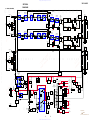
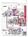
4-1. BLOCK DIAGRAM
SECTION 4
DIAGRAMS
5
6
7
5
6
7
3
2
1
6
5
7 5 7 6 7 6 7
PRE AMP
IC801 (2/2)
PHASE AMP
IC802 (2/2)
5
6
7
3
2
1
LOW BOOST
IC813 (2/2)
LINE AMP
IC813 (1/2)
H.P.F
IC803 (2/2)
L.P.F
IC804 (2/2)
L.P.F
IC805 (2/2)
DIFFERENTIAL
AMP
Q103
POWER
AMP
Q108
DRIVER
AMP
Q105
DIFFERENTIAL
AMP
Q104
POWER
AMP
Q110
DRIVER
AMP
Q107
BIAS
Q106
LEVEL
SHIFT
Q101
LEVEL
FILTER
S801-1
LPF
OFF
HPF
LEVEL
VR803-1
LOW
BOOST
B+
(+14.2V)
B–
(–14.2V)
B+
(+14.2V)
B–
(–14.2V)
CNJ805-1
CNJ805-2
CN809
VR801-1
PHASE
VR802-2
FILTER
VR802-1
FILTER
VR804-1
LINE
SWITCH
Q102
+12V
GND
REM
10
1
2
3
1 3 1 2 1 2 1
PRE AMP
IC801 (1/2)
PHASE AMP
IC802 (1/2)
3
2
1
5
6
7
LOW BOOST
IC814 (2/2)
LINE AMP
IC814 (1/2)
H.P.F
IC803 (1/2)
L.P.F
IC804 (1/2)
L.P.F
IC805 (1/2)
DIFFERENTIAL
AMP
Q203
POWER
AMP
Q208
DIFFERENTIAL
AMP
Q204
MUTE
SWITCH
Q805
POWER
AMP
Q210
DRIVER
AMP
Q207
BIAS
Q206
LEVEL
SHIFT
Q201
VR803-2
LOW
BOOST
(40Hz)
VR801-2
PHASE
VR802-3
FILTER
VR802-4
FILTER
L
HIGH
LEVEL
(INPUT (FRONT))
(INPUT (REAR))
R
L
(BTL)
INPUT
(FRONT)
INPUT
(REAR)
R
CN803
L
BTL
R
VR804-2
LINE
SWITCH
Q202
VR201
BIAS
VR101
BIAS
15
16
2
14
12
REF.
REG
CN801
F901
40A
INVERTER
Q906,907
INVERTER
Q908,909
DRIVER
Q904
DRIVER
Q905
B+ CONT
Q801
B+ CONT
Q802
TEMP DET
D801,804,805,
808,809
11
9
8
3
LD801
THERMAL
OFFSET
(PROTECTOR)
LD803
FRONT
SPEAKER
OUT
LD804
POWER
(PROTECTOR)
(PROTECTOR)
(PROTECTOR)
LD802
OVER
CURRENT
DC-DC
CONVERTER
TRANSFORMER
T901
DC-DC CONVERTER
IC901
SWITCH
Q808
• Signal path
: AUDIO
• Front-ch : same as Rear-ch.
REG
Q901,902
FILTER
S801-2
LPF
OFF
HPF
(40Hz)
OVERLOAD
DET
Q112
OVERLOAD
DET
Q212
CN804
L
BTL
R
REAR
SPEAKER
OUT
3
2
CNJ805-3
CNJ805-4
CN810
L
HIGH
LEVEL
R
L
(BTL)
R
CNJ802
B+
REG
Q910
B–
REG
Q911
B+
(+23.5V)
B+
(+42V)
B+
(+36V)
B+
(+36V)
B–
(–35V)
B–
(–35V)
B–
(–42V)
B–
(–14.2V)
B+
(+14.2V)
LED DRIVE
Q803
SWITCH
Q810
LED DRIVE
Q804
SWITCH
Q806
OFFSET
DET
Q809
OFFSET
DET
Q807
POWER
ON/OFF
Q903
DC DET
IC811
D815
D902
D910
D903
D909
D911
D906
D912
D903
RECT
D906
RECT
D909,910
RECT
D911,912
RECT
D907
D904
D908
D905
D904,905,907,908
RECT
TEST TONE
GENERATOR
IC812
(FRONT)
(REAR)
S802
TEST
TONE
B– (–35V)
D816
1
DRIVER
AMP
Q205
D812
http://www.xiaoyu163.com
http://www.xiaoyu163.com

10 10
XM-1004GX
• A : B+ Line.
• B : B– Line.
• Power voltage is dc 14.4V and fed with regulated dc power
supply from +12V and REM terminals.
• Voltage is dc with respect to ground under no-signal
condition.
• Voltages are taken with a VOM (Input impedance 10 MΩ).
Voltage variations may be noted due to normal produc-
tion tolerances.
• Waveforms are taken with a oscilloscope.
Voltage variations may be noted due to normal produc-
tion tolerances.
• Circled numbers refer to waveforms.
• Signal path.
F : AUDIO
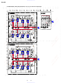
for printed wiring boards:
Note:
• X : parts extracted from the component side.
• : Pattern from the side which enables seeing.
(The other layer’s patterns are not indicated.)
• IC Block Diagram
IC901 µPC494GS-T1
16 15 14 13 12 11 10 9
1 2 3 4 5 6 7 8
OSC
REF. REG.
ERROR
ERROR
0.1V
THIS NOTE IS COMMON FOR PRINTED WIRING BOARDS
AND SCHEMATIC DIAGRAMS.
(In addition to this, the necessary note is
printed in each block.)
for schematic diagram:
Note:
• All capacitors are in µF unless otherwise noted. pF: µµF
50 WV or less are not indicated except for electrolytics
and tantalums.
• All resistors are in Ω and
1
/
4
W or less unless otherwise
specified.
• % : indicates tolerance.
• 2 : nonflammable resistor.
Q202 D-5
Q203 C-6
Q204 C-6
Q205 C-6
Q206 B-7
Q207 C-6
Q208 B-7
Q210 B-7
Q212 B-6
Q301 D-2
Q302 C-2
Q303 B-2
Q304 B-2
Q305 B-2
Q306 B-1
Q307 B-2
Q308 B-1
Q310 B-1
Q312 B-2
Q401 D-2
Q402 C-2
Q403 C-2
Q404 C-2
Q405 C-2
Q406 D-1
Q407 C-2
Q408 D-1
Q410 C-1
Q412 C-2
Q801 A-4
Q802 A-4
Q803 B-4
Q804 B-4
Q805 C-3
Q806 D-3
Q807 D-2
Q809 D-5
Q810 A-4
Q901 B-5
Q902 C-5
Q903 C-5
Q904 B-5
Q905 C-5
Q906 A-5
Q907 A-4
Q908 A-6
Q909 A-5
Q910 C-4
Q911 C-3
D801 A-7
D804 A-7
D805 A-2
D808 A-1
D809 A-5
D810 B-4
D812 B-4
D813 C-3
D814 C-3
D815 B-4
D816 A-4
D851 D-4
D901 C-5
D902 C-5
D903 B-4
D904 A-3
D905 A-4
D906 B-4
D907 A-2
D908 A-3
D909 C-4
D910 C-4
D911 C-3
D912 C-3
D913 C-3
D914 C-3
D915 C-3
D916 B-3
IC801 D-4
IC806 D-3
IC811 D-3
IC812 C-4
IC813 D-4
IC814 D-5
IC815 D-2
IC816 D-3
IC901 C-4
Q101 D-5
Q102 D-5
Q103 D-6
Q104 D-6
Q105 D-6
Q106 D-7
Q107 D-6
Q108 C-7
Q110 D-7
Q112 C-6
Q201 D-5
• Semiconductor Location (AMP SECTION)
Ref. No. Location
Ref. No. Location
Note: The components identified by mark 0 or dotted line
with mark 0 are critical for safety.
Replace only with part number specified.
http://www.xiaoyu163.com
http://www.xiaoyu163.com

11 11
XM-1004GX
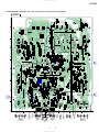
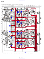
4-2. PRINTED WIRING BOARD — AMP SECTION — • Refer to page 10 for Semiconductor Location and Common Note on Printed Wiring Boards.
1
A
B
C
D
E
234 567
41
58
41
58
41
58
JR102
R821
R822
R815
R816
R335
R336
R348
R346
C321
R347
Q312
JR109
R338
R339
C320
C322
R329
R825
R805
R827
C804
R828
R867
C816
R876
ECB
Q810
AKA
AKA
AKA
BCE
ECB
ECB
ECB
ECB
BCE
BCE
D901
Q903
BCE
AKA
BCE
BCE
AKA
AKA
BCE
Q904
AKA
BCE
Q905
Q901
BCE
R871
Q801
C802
R806
C801
R802
JR103
R803
R826
R823
R824
R908
R844
R907
JR63
JR124
R121
C902
R902
R868
C122
C120
R129
R128
R130
R132
R131
R232
R147
JR92
C930
R235
R236
R239
R238
C807
JR31
R813
R814
R807
R808
C810
JR100
C929
R248
R247
R246
Q212
R254
R123
C225
C812C814
C317
C417
R419
C413
R455
IC815
IC816
R454
R319
C313
C326
R353JR107
C938
R404
C403
R303
R302
R101
R103
R420
R152
R104
C103
C205
R203
R453
R850
R326
D915
D813
Q805
R837
R432
R835
R839
R842
R843
R447
JR104
R448
Q404
Q407
Q405
Q402
Q302
Q412
Q403
R401
R402
C405
R452
R204
C203
R253
R323
R424
R324
R354
R355
R423
C428
C388
C327
R352
C303
R304
C304
R305
C305R301
C427
C425
C426
C325
R155
IC813
IC814
IC801
IC806
IC812
R223
JR64
C855
D851
R928
R927
D914
D913
Q911
Q910
R929
R930
R911
C904
R910R912
R829
R916
R915
R917
R830
R801
JR76
R831
R832
C806
Q804
JR70
JR69
R931
R860
R858
C854
JR67
R853
R857
JR60
JR61
C935
R205
C204
R252
R861
R833
JR106
JR56
D814
R862
R102
R153
C936
C937
R405
C404
R403
R840
R421 R321
R322
R422 R320
R841
JR43
JR105
C420
R429
C421
JR44
R449
R349
R439
R435
R436
R438
R446
C422
R431
R427
JR33
R428
R430
C104
R105
C105
R202
R201
R221
R126
C121
R227
R231
R230
R228
R229
C220
C221
C222
R148
R139
R138
R136
R135
R149
R249
R146
R127
R220
R222
R120
R122
R869
R870
R901
R219
C213
R255
C217
R224
JR82
R154
R124
C228
C227
C128
C127
C113
R119
C126
C125
C226
C117
C118
C219
C223
C908
C911
C912
C910
C909
C916
C914
C915
C803
C905
C817
JW163
C920
C918
C323
C919
C419
C917
C924
C940
Q304
C805
C913
C928
C923
C939
C319
C927
C808
C423
C318
C314
C315
C907
C906
C942 C941
C926
C925 C921 C922
C119
R859
C853
R855
C851
R854
C852
R856
R851
R852
C903
R909
R932
R914
R327
R332
R328
R331
R330
JR123
JR35
JR34
JR112
JR37
JR38
R334
R957
R955
R953
R951
R965
R333
R959
R961
R963
R966
JR73
JR72
JR108
R836
JR125
R923
R924
JR77
R926
JR80
JR81
R872
R873
R874
R875
R913R918
R906
Q902
R905
R970
R972
R974
R976
R978
R975
R977
R234
R237
JR91
R137
JR90
R141
JR116
R133
R225
R125
JR89
R134
R233
R904
D902
JR68
JR58
JR48
JR42
R425
R434
R437
R433
JR32
R442
R441
JR46
JR45
R325
JR47
Q806
IC811
Q807
JR50
JR54
JR55
R838
JR57
JR52
JR53
JR51JR49
JR41
Q301
Q401
JR59
R967
JR66
JR65
JR62
R863
R251
R864R866
R865
R351R451
JR39
JR40
R151
JR84
R900
R969
R971
JR86
JR87
R920
R919
R921
R922
JR71
R968
R903
JR98
JR99
JR30
JR93
R973
R142
R242
JR101
R241
R834
R925
JR119
JR75
JR78
JR79
JR122
JR121
Q802
D815
D906
D903
D810
D912
D911
D910
D909
Q803
JR74
R964
D916
R962
R960
R958
R956
R954
R952
R341
CC
BEB
CC
BEB
R337
R342
JR113
D808 D805
JW65
JW64
JW59
Q809
Q101
Q201
IC901
D809
AKA
D812
D816
Q105
Q103Q104
Q203
Q112
Q204
Q207
Q205
Q107
D804
D801
CCCC
EBBEBB
CC
EBB
CC
EBB
CC
B E B
CC
B E B
D907
L908
L907
L904
L903
L905
L906
L909
L910
L901
D904 D908
D905
Q906
Q907
Q909 Q908
JW53
TP301
TP402
TP401
TP201
TP202
TP101
TP102
TP302
JW52
JW26
JW25 JW40
JW27
JW75
JW78
JW130
JW73
JW72
C324
C424
JW76
JW77
JW81
CNP807
CNP806
JW74
JW79
JW69
JW70
R350
R456
R450
R356
JW71
JW108
JW125
JW106
JW129
JW128
JW134
JW138
JW143
JW144
JW169
JW166
R256
R250
JW167
JW168
JW147
JW146
JW145
JW135
JW136
JW139
JW140
JW133
JW141
JW142
JW126
JW170
JW171
JW180
JW185
JW193
JW194
JW220
JW206
JW209
JW210
JW211
JW212
JW215
JW160
JW156
JW155
JW154
JW158
JW159
JW157
JW161
JW219
JW196
JW175
JW184
JW179
JW180
JW173
JW172
JW123
JW124
JW186
JW187
JW188
JW200
JW164
JW199
JW207
JW218
JW217
JW216
JW208
JW201
JW202
JW189
JW190
JW152
JW151
JW176
JW177
JW174
JW181
JW148
JW149
JW131
JW132
JW112
JW111
JW110
JW97
JW98
JW34
JW32
JW33
JW35
JW93
JW92
JW113
JW114
JW115
JW116
JW99
JW46
JW60
JW44
JW43
JW41
JW42
JW45
JW39
JW37
JW90
JW91
JW87
JW89
JW28
JW24
JW23
JW22
JW21
JW88
JW36
JW38
JW105
JW153
JW104
JW117
JW120
JW118
CNP808
JW119
JW109
JW121
JW150
JW127
JW107
JW80
JW82
JW86
JW84
JW83
JW85
C811
C216
C116
C933
C931
C932
C934
C215
C115
C901
C224
C123
C124
C114
C815
Q102
Q202
C402
C809
C401
C301
C202
C813
C101
C302
C201
C214
C102
C316
C415
C414
C416
L902
JW103
JW102
JW67
JW94
JW62
JW63
Q307
Q303
Q305
JW56
JW54
JW61
R344
R244
R144
R444
JW66
JW51
JW50
JW49
JW68
JW96
JW95
R156
R150
Q406
Q408
Q410
Q306
Q206
GDS
GDS
GDSGDS
Q310
Q208
Q106
Q108
Q110
SDGSDG
SDGSDG
Q210
Q308
PL801
TH815
TH807
TH806
TH814
TH811
TH810
VR301
VR401
VR201
TH803
TH802
VR101
T901
VR807
VR808
VR804
(INPUT (REAR))
CN810
CNJ805
VR803
VR804 VR803
16 9
18
JW101
AMP BOARD
41
58
41
58
41
58
41
58
81
-2
-1
-2
-1
-1
-2
-1
-2
SDG SDGS
D
G
S
DG
TH819
TH817
15
110
A
A
B
B
RL RL
BTL
CN804
REAR SPEAKER OUT
HIGH LEVEL
(INPUT (FRONT))
(FRONT)
(FRONT)
CN809
R
L
-4
R
-2
R
-3
L (BTL)
-1
L (BTL)
HIGH LEVEL
INPUT(REAR) (FRONT)
RL
BTL
CN803
FRONT SPEAKER OUT
GND
LOW
BOOST
(40Hz)
LEVEL
VR807 VR808
(REAR)
(REAR)
LOW
BOOST
(40Hz)
LEVEL
CNJ802
REM
F901
40A
+12VCN801
1-682-372-
11
1
FILTER (A)
BOARD
CNJ806
3
LED
BOARD
CNJ808
2
FILTER (B)
BOARD
CNJ807
(Page 15)
(Page 15)
(Page 15)
http://www.xiaoyu163.com
http://www.xiaoyu163.com


15 15
XM-1004GX
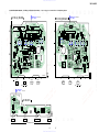
4-6. PRINTED WIRING BOARDS — FILTER (A), FILTER (B), LED SECTION — • Refer to page 10 for Common Note on Printed Wiring Boards.
A
B
1 23
A
B
1 23
R107
R207
R845
R847
R846
R849
R848
JR10
JR3
R113
JR6
R210
R106
R306
R309
R406
C329
R308
C429
R408
JR18
C946
C945
JR25
C307
R311
R413
IC808
IC807
IC809 IC810
JR20
JR19
R414
R417
R415
R316
JR202
R409
R307
C407
R411
R312
R314
JR24
R318
R317
R418
R416
R410
JR207
JR22
JR12
R315
JR11
JR13
R313
R310
JR14
R407
JR209
R412
JR208
R110
R218
R216
R217
C209
C211
C310
C312
C410
JW19
C412
C311
C411
C111
R215
C207
R211
R112
R114
R212
JR9
R118
R117
R209
1-682-373-
1-682-374-
1-682-375-
(11)
11
(11)
11
(11)
11
JR8
JR7
JR17
JR15
JR26
JR21
JR201
JR16
JR204
JR5
JR4
JR2
JR1
JR203
R214
R111
C107
C944
R116
R115
C943
R109
R206
C129
R108
JR205
JR206
R213
C229
R208
FILTER
(
A
)
BOARD
LED BOARD
FILTER
(
B
)
BOARD
IC802
IC803
IC804
IC805
14
85
14
85
14
85
14
85
110
18
JW25
JW26
JW10
JW29
JW24
JW9
JW8
JW7
JW6
JW5
JW4
JW3
JW28
JW27
JW2
JW1
C406
C306
C309
C308
C409
C408
C109
C106
C208
C108
C206
C210
C110
C112
C212
15
LD801
LD801
THERMAL
LD803
LD803
OFFSET
LD802
LD802
OVER CURRENT
LD804
LD804
POWER
3
2
CNJ808
AMP BOARD
CNP808
S801
S803
S802
S802
TEST
TONE
S801
FILTER
(FRONT)
VR802
FILTER
(FRONT)
VR806
FILTER
(REAR)
VR801
PHASE
(FRONT)
VR805
PHASE
(REAR)
VR802
VR806
VR801
VR805
LPF OFF HPF
S803
FILTER
(REAR)
LPF OFF HPF
JW11
JW21
JW18
JW17
JW20
JW23
JW22
JW12
JW13
JW14
JW15
JW16
85
14
85
14
85
14
85
14
CNJ807
CNJ806
AMP BOARD
CNP807
1
AMP BOARD
CNP806
-1
-2
-3
-1
-2-4
-1
-2
-1
-2
-3
-4
-1
-2
-1
-2
BCE
Q808
(POWER/PROTECT)
(Page 11)
(Page 11)
(Page 11)
http://www.xiaoyu163.com
http://www.xiaoyu163.com


17
XM-1004GX
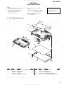
SECTION 5
EXPLODED VIEWS
• Color Indication of Appearance Parts
Example :
KNOB, BALANCE (WHITE) ... (RED)
Parts Color Cabinet’s Color
• Accessories and packing materials and
hardware (# mark) list are given in
the last of this parts list.
Ref. No. Part No. Description Remark
R
R
A
A
#1
#1
F901
#2
#1
#1
1
2
9
3
4
5
6
7
8
8
8
NOTE:
• The mechanical parts with no reference
number in the exploded views are not supplied.
• Items marked “*” are not stocked since
they are seldom required for routine service.
Some delay should be anticipated
when ordering these items.
Ref. No. Part No. Description Remark
5-1. HEAT SINK (MAIN) SECTION
1 3-225-070-11 PLATE (HEAT SINK), ORNAMENTAL
* 2 3-225-071-01 HEAT SINK (MAIN)
* 3 3-225-065-01 HOLDER, LED
4 1-682-375-11 LED BOARD
* 5 3-225-152-01 SHEET (LED), INSULATING
* 6 3-225-081-01 SHEET, INSULATING
* 7 3-225-068-01 PLATE, BOTTOM
8 3-225-185-01 SCREW (+B.TT.3X14)
9 3-225-153-01 SHEET (HEAT SINK), ADHESIVE
0 F901 1-533-743-11 FUSE (BLADE TYPE) (AUTO FUSE) 40A
The components identified by
mark 0 or dotted line with mark
0 are critical for safety.
Replace only with part number
specified.
http://www.xiaoyu163.com
http://www.xiaoyu163.com

18
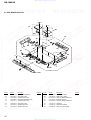
XM-1004GX
Ref. No. Part No. Description Remark Ref. No. Part No. Description Remark
5-2. AMP BOARD SECTION
51
52
53
54
66
56
55
54
56
55
57
58
59
59
59
64
66
65
64
60
#3
#3
#4
#4
61
62
62
63
51 A-3340-162-A AMP BOARD, COMPLETE
* 52 3-225-067-01 HEAT SINK (SUB 2)
53 3-225-183-01 SCREW (+PSW.TT.3XL)
* 54 3-225-080-01 HEAT SINK (RETAINER PLATE)
55 3-225-183-11 SCREW (+PSW.TT.3XL)
* 56 3-226-618-01 HEAT SINK (SUB 3)
* 57 3-225-073-01 BRACKET (4CH.VR2)
* 58 3-225-072-01 BRACKET (4CH.VR1)
59 3-225-184-01 SCREW (+PS.TT.3X6)
* 60 3-225-074-01 PANEL (4CH), FRONT
61 A-3340-163-A FILTER (A) BOARD, COMPLETE
* 62 3-225-076-01 BRACKET (5CH.VR3)
63 A-3340-164-A FILTER (B) BOARD, COMPLETE
64 3-912-431-01 SCREW (P)
65 3-369-647-01 SCREW (M4 SPACER)
* 66 3-225-086-01 SHEET (TR), INSULATING
http://www.xiaoyu163.com
http://www.xiaoyu163.com

19
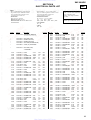
XM-1004GX
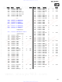
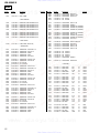
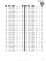
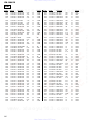
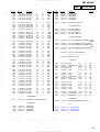
SECTION 6
ELECTRICAL PARTS LIST
Ref. No. Part No. Description Remark Ref. No. Part No. Description Remark
NOTE:
• Due to standardization, replacements in
the parts list may be different from the
parts specified in the diagrams or the
components used on the set.
• RESISTORS
All resistors are in ohms.
METAL:Metal-film resistor.
METAL OXIDE: Metal oxide-film resistor.
F:nonflammable
• Items marked “*” are not stocked since
they are seldom required for routine service.
Some delay should be anticipated
when ordering these items.
• SEMICONDUCTORS
In each case, u : µ, for example:
uA.. : µA.. uPA.. : µPA..
uPB.. : µPB.. uPC.. : µPC.. uPD.. : µPD..
• CAPACITORS
uF : µF
• COILS
uH : µH
A-3340-162-A AMP BOARD, COMPLETE
*********************
* 3-225-067-01 HEAT SINK (SUB 2)
* 3-225-072-01 BRACKET (4CH.VR1)
* 3-225-073-01 BRACKET (4CH.VR2)
* 3-225-080-01 HEAT SINK (RETAINER PLATE)
* 3-225-086-01 SHEET (TR), INSULATING
* 3-226-618-01 HEAT SINK (SUB 3)
< CAPACITOR >
C101 1-126-047-11 ELECT 4.7uF 20% 50V
C102 1-126-047-11 ELECT 4.7uF 20% 50V
C103 1-162-927-11 CERAMIC CHIP 100PF 5% 50V
C104 1-162-927-11 CERAMIC CHIP 100PF 5% 50V
C105 1-162-923-11 CERAMIC CHIP 47PF 5% 50V
C113 1-162-923-11 CERAMIC CHIP 47PF 5% 50V
C114 1-126-047-11 ELECT 4.7uF 20% 50V
C115 1-136-169-00 FILM 0.22uF 5% 50V
C116 1-126-047-11 ELECT 4.7uF 20% 50V
C117 1-162-927-11 CERAMIC CHIP 100PF 5% 50V
C118 1-126-022-11 ELECT 47uF 20% 25V
C119 1-126-022-11 ELECT 47uF 20% 25V
C120 1-162-917-11 CERAMIC CHIP 15PF 5% 50V
C121 1-107-826-11 CERAMIC CHIP 0.1uF 10% 16V
C122 1-107-826-11 CERAMIC CHIP 0.1uF 10% 16V
C123 1-136-165-00 FILM 0.1uF 5% 50V
C124 1-136-161-00 FILM 0.047uF 5% 50V
C125 1-162-927-11 CERAMIC CHIP 100PF 5% 50V
C126 1-162-927-11 CERAMIC CHIP 100PF 5% 50V
C127 1-164-489-11 CERAMIC CHIP 0.22uF 10% 16V
C128 1-164-489-11 CERAMIC CHIP 0.22uF 10% 16V
C201 1-126-047-11 ELECT 4.7uF 20% 50V
C202 1-126-047-11 ELECT 4.7uF 20% 50V
C203 1-162-927-11 CERAMIC CHIP 100PF 5% 50V
C204 1-162-927-11 CERAMIC CHIP 100PF 5% 50V
C205 1-162-923-11 CERAMIC CHIP 47PF 5% 50V
C213 1-162-923-11 CERAMIC CHIP 47PF 5% 50V
C214 1-126-047-11 ELECT 4.7uF 20% 50V
C215 1-136-169-00 FILM 0.22uF 5% 50V
C216 1-126-047-11 ELECT 4.7uF 20% 50V
C217 1-162-927-11 CERAMIC CHIP 100PF 5% 50V
C219 1-126-022-11 ELECT 47uF 20% 25V
C220 1-162-917-11 CERAMIC CHIP 15PF 5% 50V
C221 1-107-826-11 CERAMIC CHIP 0.1uF 10% 16V
C222 1-107-826-11 CERAMIC CHIP 0.1uF 10% 16V
C223 1-136-165-00 FILM 0.1uF 5% 50V
C224 1-136-161-00 FILM 0.047uF 5% 50V
C225 1-162-927-11 CERAMIC CHIP 100PF 5% 50V
C226 1-162-927-11 CERAMIC CHIP 100PF 5% 50V
C227 1-164-489-11 CERAMIC CHIP 0.22uF 10% 16V
C228 1-164-489-11 CERAMIC CHIP 0.22uF 10% 16V
C301 1-126-047-11 ELECT 4.7uF 20% 50V
C302 1-126-047-11 ELECT 4.7uF 20% 50V
C303 1-162-927-11 CERAMIC CHIP 100PF 5% 50V
C304 1-162-927-11 CERAMIC CHIP 100PF 5% 50V
C305 1-162-923-11 CERAMIC CHIP 47PF 5% 50V
C313 1-162-923-11 CERAMIC CHIP 47PF 5% 50V
C314 1-126-047-11 ELECT 4.7uF 20% 50V
C315 1-136-169-00 FILM 0.22uF 5% 50V
C316 1-126-047-11 ELECT 4.7uF 20% 50V
C317 1-162-927-11 CERAMIC CHIP 100PF 5% 50V
C318 1-126-022-11 ELECT 47uF 20% 25V
C319 1-126-022-11 ELECT 47uF 20% 25V
C320 1-162-917-11 CERAMIC CHIP 15PF 5% 50V
C321 1-107-826-11 CERAMIC CHIP 0.1uF 10% 16V
C322 1-107-826-11 CERAMIC CHIP 0.1uF 10% 16V
C323 1-136-165-00 FILM 0.1uF 5% 50V
C324 1-136-161-00 FILM 0.047uF 5% 50V
C325 1-162-927-11 CERAMIC CHIP 100PF 5% 50V
C326 1-162-927-11 CERAMIC CHIP 100PF 5% 50V
C327 1-164-489-11 CERAMIC CHIP 0.22uF 10% 16V
C328 1-164-489-11 CERAMIC CHIP 0.22uF 10% 16V
C401 1-126-047-11 ELECT 4.7uF 20% 50V
C402 1-126-047-11 ELECT 4.7uF 20% 50V
C403 1-162-927-11 CERAMIC CHIP 100PF 5% 50V
C404 1-162-927-11 CERAMIC CHIP 100PF 5% 50V
C405 1-162-923-11 CERAMIC CHIP 47PF 5% 50V
C413 1-162-923-11 CERAMIC CHIP 47PF 5% 50V
C414 1-126-047-11 ELECT 4.7uF 20% 50V
C415 1-136-169-00 FILM 0.22uF 5% 50V
C416 1-126-047-11 ELECT 4.7uF 20% 50V
C417 1-162-927-11 CERAMIC CHIP 100PF 5% 50V
C419 1-126-022-11 ELECT 47uF 20% 25V
C420 1-162-917-11 CERAMIC CHIP 15PF 5% 50V
C421 1-107-826-11 CERAMIC CHIP 0.1uF 10% 16V
C422 1-107-826-11 CERAMIC CHIP 0.1uF 10% 16V
C423 1-136-165-00 FILM 0.1uF 5% 50V
C424 1-136-161-00 FILM 0.047uF 5% 50V
C425 1-162-927-11 CERAMIC CHIP 100PF 5% 50V
AMP
The components identified by
mark 0 or dotted line with mark
0 are critical for safety.
Replace only with part number
specified.
When indicating parts by reference
number, please include the board.
http://www.xiaoyu163.com
http://www.xiaoyu163.com

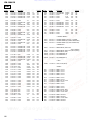
20
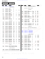
XM-1004GX
Ref. No. Part No. Description Remark Ref. No. Part No. Description Remark
C426 1-162-927-11 CERAMIC CHIP 100PF 5% 50V
C427 1-164-489-11 CERAMIC CHIP 0.22uF 10% 16V
C428 1-164-489-11 CERAMIC CHIP 0.22uF 10% 16V
C801 1-163-021-11 CERAMIC CHIP 0.01uF 10% 50V
C802 1-107-826-11 CERAMIC CHIP 0.1uF 10% 16V
C803 1-126-960-11 ELECT 1uF 20% 50V
C804 1-162-962-11 CERAMIC CHIP 470PF 10% 50V
C805 1-126-965-11 ELECT 22uF 20% 50V
C806 1-162-962-11 CERAMIC CHIP 470PF 10% 50V
C807 1-107-826-11 CERAMIC CHIP 0.1uF 10% 16V
C808 1-126-965-11 ELECT 22uF 20% 50V
C809 1-104-664-11 ELECT 47uF 20% 25V
C810 1-107-826-11 CERAMIC CHIP 0.1uF 10% 16V
C811 1-126-960-11 ELECT 1uF 20% 50V
C812 1-164-489-11 CERAMIC CHIP 0.22uF 10% 16V
C813 1-126-934-11 ELECT 220uF 20% 16V
C814 1-164-489-11 CERAMIC CHIP 0.22uF 10% 16V
C815 1-104-664-11 ELECT 47uF 20% 25V
C816 1-107-826-11 CERAMIC CHIP 0.1uF 10% 16V
C817 1-126-965-11 ELECT 22uF 20% 50V
C851 1-163-021-11 CERAMIC CHIP 0.01uF 10% 50V
C852 1-163-021-11 CERAMIC CHIP 0.01uF 10% 50V
C853 1-163-021-11 CERAMIC CHIP 0.01uF 10% 50V
C854 1-163-021-11 CERAMIC CHIP 0.01uF 10% 50V
C855 1-107-826-11 CERAMIC CHIP 0.1uF 10% 16V
C901 1-137-194-11 FILM 0.47uF 5% 50V
C902 1-162-964-11 CERAMIC CHIP 0.001uF 10% 50V
C903 1-163-021-11 CERAMIC CHIP 0.01uF 10% 50V
C904 1-162-964-11 CERAMIC CHIP 0.001uF 10% 50V
C905 1-104-664-11 ELECT 47uF 20% 25V
C906 1-126-965-11 ELECT 22uF 20% 50V
C907 1-126-933-11 ELECT 100uF 20% 16V
C908 1-136-153-00 FILM 0.01uF 5% 50V
C909 1-131-731-11 ELECT 2200uF 20% 16V
C910 1-131-731-11 ELECT 2200uF 20% 16V
C911 1-131-731-11 ELECT 2200uF 20% 16V
C912 1-131-731-11 ELECT 2200uF 20% 16V
C913 1-126-973-11 ELECT 2200uF 20% 50V
C914 1-126-973-11 ELECT 2200uF 20% 50V
C915 1-126-973-11 ELECT 2200uF 20% 50V
C916 1-126-973-11 ELECT 2200uF 20% 50V
C917 1-126-973-11 ELECT 2200uF 20% 50V
C918 1-126-973-11 ELECT 2200uF 20% 50V
C919 1-126-973-11 ELECT 2200uF 20% 50V
C920 1-126-973-11 ELECT 2200uF 20% 50V
C921 1-136-165-00 FILM 0.1uF 5% 50V
C922 1-136-165-00 FILM 0.1uF 5% 50V
C923 1-136-165-00 FILM 0.1uF 5% 50V
C924 1-136-165-00 FILM 0.1uF 5% 50V
C925 1-126-960-11 ELECT 1uF 20% 50V
C926 1-126-960-11 ELECT 1uF 20% 50V
C927 1-128-576-11 ELECT 100uF 20% 63V
C928 1-128-576-11 ELECT 100uF 20% 63V
C929 1-162-964-11 CERAMIC CHIP 0.001uF 10% 50V
C930 1-162-964-11 CERAMIC CHIP 0.001uF 10% 50V
C931 1-126-963-11 ELECT 4.7uF 20% 50V
C932 1-126-963-11 ELECT 4.7uF 20% 50V
C933 1-126-933-11 ELECT 100uF 20% 16V
C934 1-126-933-11 ELECT 100uF 20% 16V
C935 1-163-021-11 CERAMIC CHIP 0.01uF 10% 50V
C936 1-163-021-11 CERAMIC CHIP 0.01uF 10% 50V
C937 1-163-021-11 CERAMIC CHIP 0.01uF 10% 50V
C938 1-163-021-11 CERAMIC CHIP 0.01uF 10% 50V
C939 1-126-960-11 ELECT 1uF 20% 50V
C940 1-126-960-11 ELECT 1uF 20% 50V
C941 1-104-665-11 ELECT 100uF 20% 25V
C942 1-104-665-11 ELECT 100uF 20% 25V
< TERMINAL BOARD >
CN801 1-694-755-11 TERMINAL BOARD (2P+FUSE) (+12V,GND)
CN803 1-694-756-11 TERMINAL BOARD (4P) (FRONT SPEAKER OUT)
CN804 1-694-756-11 TERMINAL BOARD (4P) (REAR SPEAKER OUT)
< CONNECTOR >
CN809 1-794-219-11 CONNECTOR 4P (HIGH LEVEL
(INPUT (FRONT)))
CN810 1-794-219-11 CONNECTOR 4P (HIGH LEVEL (INPUT (REAR)))
CNJ802 1-815-300-11 CONNECTOR 1P (REM)
CNP806 1-815-823-11 PIN, CONNECTOR 10P
CNP807 1-815-822-11 PIN, CONNECTOR 8P
* CNP808 1-568-954-11 PIN, CONNECTOR 5P
< JACK >
CNJ805 1-779-078-41 JACK, PIN 4P (INPUT)
< DIODE >
D801 8-719-801-78 DIODE 1SS184
D804 8-719-801-78 DIODE 1SS184
D805 8-719-801-78 DIODE 1SS184
D808 8-719-801-78 DIODE 1SS184
D809 8-719-801-78 DIODE 1SS184
D810 8-719-016-74 DIODE 1SS352
D812 8-719-801-78 DIODE 1SS184
D813 8-719-978-33 DIODE DTZ-TT11-6.8B
D814 8-719-016-74 DIODE 1SS352
D815 8-719-016-74 DIODE 1SS352
D816 8-719-016-74 DIODE 1SS352
D851 8-719-801-78 DIODE 1SS184
D901 8-719-025-50 DIODE 02CZ16-TE85L
D902 8-719-978-33 DIODE DTZ-TT11-6.8B
D903 8-719-054-55 DIODE 1SS306-TE85L
D904 8-719-079-00 DIODE FCH10A15
D905 8-719-079-01 DIODE FRH10A15
D906 8-719-054-55 DIODE 1SS306-TE85L
D907 8-719-079-00 DIODE FCH10A15
D908 8-719-079-01 DIODE FRH10A15
AMP
http://www.xiaoyu163.com
http://www.xiaoyu163.com
La page est en cours de chargement...
La page est en cours de chargement...
La page est en cours de chargement...
La page est en cours de chargement...
La page est en cours de chargement...
La page est en cours de chargement...
La page est en cours de chargement...
La page est en cours de chargement...
-
 1
1
-
 2
2
-
 3
3
-
 4
4
-
 5
5
-
 6
6
-
 7
7
-
 8
8
-
 9
9
-
 10
10
-
 11
11
-
 12
12
-
 13
13
-
 14
14
-
 15
15
-
 16
16
-
 17
17
-
 18
18
-
 19
19
-
 20
20
-
 21
21
-
 22
22
-
 23
23
-
 24
24
-
 25
25
-
 26
26
-
 27
27
-
 28
28


Sony XM-1004GX Manuel utilisateur
- Catégorie
- Amplificateurs audio de voiture
- Taper
- Manuel utilisateur
Documents connexes
-
Sony XM-754SX Mode d'emploi
-
Sony XM-475GSX Mode d'emploi
-
-
Sony XM-1502SX Manuel utilisateur
-
Sony xplod xm-1502sx Manuel utilisateur
-
-
Sony XM-460GTX Manuel utilisateur
-
-
-
Autres documents
-
ONKYO HT-R420 Manuel utilisateur
-
 Cubii JR2 Elliptical Bike Pedal Exerciser Le manuel du propriétaire
-
Compaq NSZ2107STTUW Manuel utilisateur
-
iGuzzini R944 Guide d'installation
-
-
-
-
-
-
