
GEPppliances.com
=3
0
Safety Instructions ......... 2, 3
Operating Instructions
Fan Control .................. 4
light Control ................ 4
Care and Cleaning
Grease Filters ................ 5
Hood Lights ................. 6
Stainless Steel Surfhces ......... 5
Installation Instructions ...7-18
Troubleshooting Tips ........ 19
Consumer Support
Consumer Support .......... 24
Owner Registration ....... 21, 22
Warranty ................... 23
CV936
Write the model and serial
numbers here:
Model #
Serial #
You can find them on a label
on the inside of the hood°
LI1275A 49-80521-2 08-09Jfl

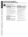
iMPORTANTSAFETYiNFORMATiON.
READALLiNSTRUCTiONSBEFOREUSING.
SAFETYPRECAUTIONS
,i_ WARNING- TOREBUCETHERiSK
OFFIRE,ELECTRICSHOCKORiNJURYTOPERSONS,
OBSERVETHEFOLLOWING:
A.
Use this unit only in the manner intended
by the manufacturer. If you have quesuons,
contact tile manufhcturer.
B. Before servicing or cleaning unit, sxdtch
power offal service panel and lock tile service
disconnecting means to prevent power fiom
being switched on accidentalb: _\_len tile
service disconnecting means cannot be locked,
securely fasten a prominent warning dedce,
such as a tag, to tile service panel.
C. Do not use this unit xdth any solid-state speed
control device.
D. This unit nmst be grounded.
X_,CAUTION-Forgeneralventilatinguse
only. Donot use to exhausthazardousor explosive
materials and vapors.
XILCAUTION-rereducerisko_ireand
to properly exhaustair,besure to duct air outside.
Donot vent exhaustair intospaces within walls
or ceilings or into attics, crawl spaces or garages.
,_ WARNING- ToREBUCETHERiSK
OFiNJURYTOPERSONSiN THEEVENTOFA RANGE
TOPGREASEFiRE,OBSERVETHEFOLLOWING*:
A. SMOTHER FIAMES _dth a close4itting
lid, cookie sheet or metal tray, then turn off
tile burner. BE CAREFUL TO PRE\%NT
BURNS. If tile flames do not go out
immediatel}; E_ACUATE AND CMI_
THE FIRE DEPARTMENT.
B. NEVER PICK UP A FLAMING PAN--
You rnW be burned.
C. DO NOT USE _\ATER, including wet
dishcloths or mwels--a x4olent steam
explosion will result.
D. Use an extinguisher ONLY if".
1. You know you have a Class Agc
extinguishei; and you already know how
to operate it.
2. Tile fire is small and contained in tile
area where it started.
3. Tile fire department is being called.
4. You can fight tile fire x_dthyour back to
an e_t.
* Based on "Kitchen Fire Safety Tips" published
by NFPA.
2

GEAppliances.com
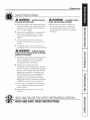
SAFETYPRECAUTIONS
WARNING- TOREBUCETHERISK
OFA RANGETOPGREASEFIRE:
A. Never leave surface units unattended at high
settings, goilovers cause smoking and greasy
spillovers that may ignite. Heat oils slowly on
low or medium settings.
B. Always turn hood ON when cooldng on high
heat or when flamb_ing fbod (i.e. Crepes
S_tzette, CherfiesJubilee, Peppercorn Beef
Idamb_).
C_
Clean ventilating fans flequen@ Grease
should not be allowed to accumulate on fan
or filter.
D. Use proper pan size. Always use cookware
appropriate fbr tile size of tile surface element.
WARNING- TOREBUCETHERISK
OFFIRE,ELECTRICSHOCKORINJURYTOPERSONS,
OBSERVETHEFOLLOWING:
A_
C_
Installation work and electrical _dring must be
done by qualified person(s) in accor<tance
_dth all applicable codes and start<lards,
including fire-rated construction.
Sufficient air is needed fbr proper
combustion and exhausting of gases through
tile flue (chimney) of fuel burning equipment
to prevent back drafting. Follow tile heating
equipment mam_hcmrer's gtfidelines and
safety standards such as those published by
tile National Fire Protection Association
(NFPA), tile American Society fbr Heating,
Refrigeration and Air Conditioning Enfneers
(ASHRAE) and tile local code authorities.
V_llen cutting or drilling into wall or ceiling,
do not damage electrical wiring and other
hidden utilities.
D. Ducted fans must alwaysbe vented to tile
outdoors.
WARNING- TOREBUCETHERISK
OFFIRE,USEONLYMETALDUCTWORK
Do not attempt to repair or replace an},
part of your hood unless it is specifically
recommended in this manual. All other
ser_4cing should be referred to a qualified
technician.
READANDFOLLOWTHISSAFETYINFORMATIONCAREFULLY.
READAND SAVETHESEiNSTRUCTiONS
3

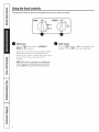
Usingthehoodcontrols.
Throughout this manual, features and appearance may vary from your model.
OFF_ LO LIGHT OFF
, @'
NED LO
] NITE
MED HI
/
HI
,j
0 FAN Control
Turn the FANspeed conQol to tO, MEOtO,
MEB H/ or H/,;_s needed°
Continuous use of the f_m system while cooking
helps keep the kitchen comKnmble and less
humid. It also reduces cooking odors and soiling
moisture that c_eate a flequent need K)r
cleaning.
NOTE:Whenthe fan is operating on the LOsetting,
it will be very quiet.Always make sure that the fan
is turned OFFwhen you are finished in the kitchen.
0 tIGHT Control
Turn die tlGHYconuol to HI for bright light while
cooking. Turn m NITEK_r use as a night light.
4

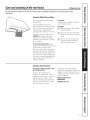
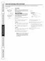
Care and cleaning of the vent hood. aappliancescom
Be sure electrical power is off and all surfaces are cool before cleaning or servicing any part of the
vent hood.
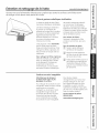
Reusable Metal Grease Filters
The hood has 2 metal reusable
grease filters.
The metal filters trap grease
released by foods on the cooktop.
They also help prevent flaming
foods on the cooktop flom
damaging the inside of the hood.
For this reason, the filters must
ALWAYS be in place when the
hood is used. The grease filters
should be cleaned once a month,
or as needed.
Toclean the grease filters, soak
them and then swish them around
in hot water and detergent.
Don't use ammonia or ammonia
products because they will darken
the metal. Do not use abrasives or
oven cleaners, i,ight brushing can
be used to remove embedded dirt.
Rinse, shake and let them dry
before replacing.
To remove:
Grasp the filter handle and pull it
up, fbrward and out.
Toreplace:
[_ Hold the filter at the bottom
with the handle.
[_ Place the top end of the filter
against the inside flont of the
hood.
[_ Slide it up until it stops and
push the bottom end back
until it snaps into place.
Stainless Steel Surfaces
Oo notuse a steel wool pa& # will
scratchthesurface.
To clean the stainless steel
stlIf_ce, tlse warIIl sudsy water or
a stainless steel cleaner or polish.
Always wipe the surfime in the
direction of the grain. Follow the
cleaner instructions for cleaning
the stainless steel smface.
To inquire about prochasing
stainless steel appliance cleaner or
polish, or to find the location of a
dealer nearest you, please call our
toll-flee nmnber:
NationalParts Center
800.626.2002
GEAppliances.com
5

Care and cleaning of the vent hood.
Be sure electrical power is off and aftsurfaces are cool before cleaning or servicing any part of
the vent hood.
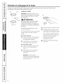
Receptacle Socket Hood Lights
/
ii
/
Glasscover
\ Bulb
NOTE:The glass cover should be removed
only when cold. Wearing latex gloves may
offer a better grip.
A CAUT/O_V.. Before replacing
your light bulb, disconnect the electrical
power to the hood at the main fuse or
circuit breaker panel.
Be sure to let file light cover and bulb cool
completely.
For your safeb,, do not touch a hot bulb
with bare hands or a damp cloth.
TO remove:
[_ Turn the glass cover counterclockwise
until the glass cover clea_ the socket.
[_ Using gloves or a (hT cloth, remove
the bulb by pulling it straight out.
Toreplace:
S c ) c •
[y] U_e a new 12w(lt, 20-watt (maxmmm)
Halogen bulb for a (;-4 base.
Receptacle
/
orcloth _
Push the bulb straight into the
receptacle all the way.
Place the gl_kss cover onto the socket
and mrn clockwise undl secure.
For improved lighting, clean file glass
cover fiequently using a damp cloth.
This should be done when the hood
is complemly cool.
[_ Reconnect electrical power to
the hood.
[_ Using gloves or a (hT cloth, remove
the new bulb flom its packaging.
NOTE:Donot touch thenewhalogen bulb
with bare fingers.Touchingthebulb with
bare fingers will significantlyreduce the
life of thebulb.
6

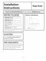
Installation
instructions
RangeHoods
m
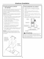
BEFORE YOU BEGIN
Read these instructions completely and carefully.
•IMPORTANT- S.ve_hesei.s_,uc_io.s
for local inspector's use.
•IMPORTANT- Obse,ve.ll,_ove,.i._
codes and ordinances.
• Note to Installer - Be sure to leave these instruc-
tions with the Consmner.
• Note to Consumer - Keep these instructions for
furore reference.
• Skill Level - Installation of this vent hood requires
basic mechanical and electrical skills.
•Completion time - 1 to 3 hours.
• Proper installation is the responsibiliD_ of the installer.
• Product failure due to improper installation is not
covered under the _uranty.
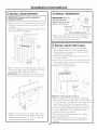
PRODUCT DIMENSIONS
18
i
30" Models
Requirea30"Wide Opening
ACAUTION:
Due to the weight and size of these vent hoods and to
reduce the risk of personal i_j ury or damage to the
product, TWO PEOPLE ARE REQUIRED FOR
PROPER INSTALLATION.
FOR YOUR SAFETY:
Before beginning the installation, switch power off at
service panel and lock the smMce disconnecting means
to prevent power fiom being switched on accidentally.
When the se_wice disconnecting means cannot be
locked, securely fasten a prominent warning device,
such as a rag, to the service panel.

Installation instructions
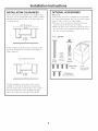
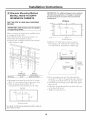
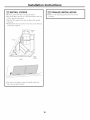
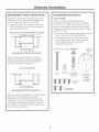
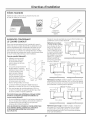
iNSTALLATiON CLEARANCES
These vent hoods are designed to be installed onto a
wall. They may be installed beneath a soffit or cabinet.
* Install these hoods 24" Min. to 36" Max. above the
cooking surface.
SOFFITINSTALLATION
SOFFIT
24"MIN.
36" MAX.
it--
In this installation the ductwork running from the
top of the hood will be concealed in the soffit or
upper cabinet_ T.
WALLMOUNTINSTALLATION
For this installation, a decorative duct cover is
available to conceal the duct_,vork running flom
the top of the hood. Use of the duct cover requires
special consideration to the installation height
above the countertop. See page 12 for details.
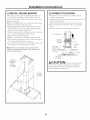
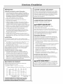
OPTIONAL ACCESSORIES
Duct Cover
A Decorative duct cover is available to accommodate
8 to 10 ft. ceiling heights. The duct cover will expand
flom 12" Min. or 24" to 34 "Max. height.
* The duct cover conceals the ductwork running
flom the top of the hood to the ceiling.
* Order the duct cover accessory at the same time as
the vent hood. All accessories should be on site at
the dine of hood installation.
Order: JXCHSS
2 Wood
Screws
2Washers
2WaII
Fasteners
g T 2 PhillipsHead
Decorative Screws
CeilingBracket
2-Piece
DuctCoverWith
CeilingBracket
8

Installation instructions
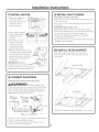
ADVANCE PLANNING
Ductwork Planning
. This hood may be vented vertically through upper
cabinets, soffit or ceiling. A duct transition piece is
supplied for vertical exhaust. Use locally supplied
elbows to vent horizontally through the rear wall.
See page 13.
* Determine the exact location of the vent hood.
* Plan the route for venting exhaust to the outdoors°
* Use the shortest and straightest duct rotlte possible.
For safisfhctory peffbrmance, duct run should not
exceed 100 R. equivalent length for any duct
configurations.
* Refer to "Duct Fittings" chart to compute the maximum
permissible length for duct runs to the outdoors.
* Use metal duct_,vork only.
* A transition piece for 7" round duct is supplied. Use
7" rotuxd duct or you may use 3-1/4" x 12" rectangular.
* Install a wall cap or roof cap with damper at the
exterior opening. Order the wall or roof cap and
any transition needed in advance.
Kit -JXDW1
Order kitJXDW1 if your installation requires horizon ml
ducfing fi'om the top of the hood through the back _vtll and:
* You have an 8 fL ceiling and need to use aJXCH
Series Chimney Corm; or
* You have a 12" cabinet or 12" soffit that the hood is to
be mounted beneath.
This kit provides a duct transition fiom 7" round to
3¼" x 10" rectangular for through-the-wall venting.
Wall Framing for Adequate Support
* This vent hood is heavy. Adequate structural support
must be provided. The hood must be secured to
vertical studs in the wall. See page 14.
* We strongly recommend that the vent hood with
duct cover be on site before final f]aming and wall
finishing. This will also help to accurately locate the
ductwork and electrical service.
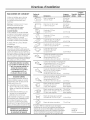
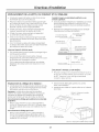
DUCT FiTTiNGS
Follow these guidelines fin proper duct sizing in the
ducting charts.
DUCTIN6CHART-30"Models
EquivalentLengthinFeetFor7" RoundDuct
Z 0 25 50 75 100 125 150
E
>
600
500
400
300
200
7" Round90° Elbow= 14ft. 7" RoofCap=39ft.
MAXIMUM DUCT LENGTH: 7" dia. duct should not
exceed 100 equivalent feet.
DECORATIVE DUCT COVERS
A decorative duct cover is available. The duct cover
conceals the ductwork running f?om the top of the
hood to the ceiling or soffit. The duct cover will fit
8 R. to 10 R. ceiling heights. See page 12 for details.
POWER SUPPLY
IMPORTANT- (Please read carefully)
,&WARNING'.
FOR PERSONAL SAFETY, THIS APPLIANCE MUST
BE PROPERIX GROU NDED.
Remove house fl_se or open circuit breaker before
beginning installation.
Do not use an extension cord or adapter plug with
this appliance. Follow National Electrical Code or
prevailing local codes and ordinances.
Electrical supply
This vent hood must be supplied with 120V, 60Hz, and
connected to an individual, properly grounded branch
circuit, and protected by a 15 or 20 amp circuit breaker
or time delay fl_se.
* Wiring must be 2 wire with ground.
* If the electrical supply does not meet the above
requirements, call a licensed electrician before
proceeding.
* Route house wiring as close to the installation
location as possible in the ceiling, soffit or wall.
See page 13 for details.
* Connect the wiring to the house wiring in
accordance with local codes.
Grounding instructions
The grounding conductor must be connected to a
grounded metal, permanent wiring system, or an
equipment-grounding terminal or lead on the hood.
AWARNING"
[]The improper connection
of the equipment-grounding conductor can result in a
risk of electric shock. Check with a qualified electrician
or service representative if you are in doubt whether
the appliance is properly grounded.
9

Installation instructions
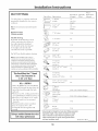
DUCT FiTTiNGS
Use this chart to compute maximum
permissible lengths for duct runs to
Outdoors.
Note: Donotexceedmaximumpermissibleequivalent
lengths!
Maximum duct length:
100 foot for vent hoods•
Flexible ducting:
If flexible metal ducting is used,
all the equivalent feet values in
the ruble should be doubled.
The flexible metal duct should
be straight and smooth and
extended as much as possible.
Do NOT use flexible plastic ducting.
Note: Anyhomeventilation system,suchasa
ventilation hood,mayinterrupttheproperflow of
combustionair andexhaustrequiredbyfireplaces,
gasfurnaces,gaswater heatersandothernaturally
ventedsystems.Tominimizethechanceofinterruption
ofsuchnaturallyventedsystems,follow the heating
equipmentmanufacturer'sguidelinesandsafety
standardssuchasthosepublishedby NFPAandASHRAE.
Duct Piece Dimensions
7" Round,straight
• -1/4 x 12"
straight
7" 90° elb(m
7" 45 °elbox_
• -1/4 x 12"
90 ° elbo_
• -1/4 x 12"
45 ° elb o_,_
:_ p*• -I/4 x 12"
90 ° fiat elbo_
Total
Equivalent Quandty Equivalent
Length* Used Length
ltt.
(per %ot
length)
lit.
(per foot
length)
14it.
9it.
15 ft.
9it.
36fl.
@_11_ 7 p' i'Ot/lld to
p,• -1/4 x12"
transition
• -1/4 xl2"to / rmnd
transition
lit.
lit.
This HoodMust Use 7" Round
Duct. It CanTransition To
3=1/4,, × 12" Duct
Kit - JXDWI
Order ldtJXDW1 if your installation
requires horizontal ducfing f)om the
top of the hood through the back
wall and:
*You have an 8 fk. ceiling and need to
use aJXCH Series Chimney Corm; or
* You have a 12"cabinet or 12" soflit
that the hood is to be mounted
beneath.
This ldt provides a duct transition
f}'oIIl 7** rotlnd to 31/4 " X 10"
rectangular for through-the-wall
venting.
Using a smaller diameter duct size
will reduce performance
7 p*I'Ot/lld to
•-1/4 x 12"
transition 90° elb(m
• -1/4 x12 t_ / rmnd
transition 90° elb(m
7" Round
wall cap
with damper
• -1/4 x 12"
_all cap _ith
damper
4it.
4it.
28 it. (21 it. x_ithout damper)
26 it. (19 it. x_ithout damper)
7" Round
roof cap 39 fk
Round
roof vent 24 ft.
*Actual length of straight duct plusduct fitting equivalent.
Equivalentlength of duct piecesare basedon actual
testsconductedby GEEvaluationEngineeringand
reflectrequirementsfor good venting performance
with any ventilation hood. Total Duct Run
10

Installation instructions
TOOLS AND MATERIALS
REQU iRED INOTSUPPUEDI
Pencil and Phillipsand
tape measure Hat blade screwdrivers
Ducttape
1/8"and 3/8" bits
Spirit level
Flashlight
1/4"pivoting hex socket
Safety glasses
UL ListedWire nuts
Pliers
Hammer Tin Snips
Wire Cutter/
Stripper
Ladder
Saber saw or Key Hole Saw
Allen
Wrench
AdditioaalMaterials:
,120V 60Hz.15or 20Amp,2wire with ground.
Properly grounded branch circuit.
, Strain relief for junction box.
,7" round metal duct, 3-1/4" x 10" rectangular duct
or 3-1/4" x 12" rectangular duct length to suit installation.
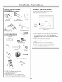
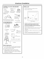
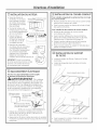
REMOVE THE PACKAGING
= Remove the small box housing the motor.
* i,iff the hood out of the box.
Wood
Mounting
Support
i
/ ,/
Hood,:::7
i I /
! ,,:7
Motor I ,",'" Parts
,/
' ' '* Package
I II /
,__2............. ",t ...............
Shipping Carton
* Remove shipping screws holding tile wood mounting
piece to tile back side of tile hood. Set aside wood
mounting piece and screws for later installation. Do not
discard.
* Remove tlle"V" shaped carton insert.
* Remove parts package flom tile "V" shaped cardboard
insert.
* Removej unction box cover and knockout.
* Install strain relief onto back or top of hood.
* Remove all tape and packing material flom tile
hood, duct transition and motor.
11

Installation instructions
PARTS PROVIDED
i,ocate the hardware accessory box packed with the
hood and check contents.
@
2Aluminum Screws, wall
Grease Filters fasteners, washers
Duct
Transition
with Damper
Filter
Support
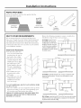
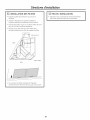
DUCT COVER REQUIREMENTS
We recommend that the vent hood and decorative
duct cover (if used) be on site before final flaming and
wall finishing. This will help to accurately locate studs,
ductwork and electrical service. Read these instructions
to determine if the duct cover accesso_ T can be used for
your installation situation.
Duct Cover Accessory:
* Use the decorative duct
cover to conceal duct_,vork
running flom the top of
the hood to the ceiling°
* The duct cover accessory
consists of 2 pieces. The
outside piece is 12" high,
the inside piece is 22".
Nested together they are
24" rain., expanding to
a total maximum height
of 34 ".
* The outside piece can
be used alone to fill a
12" height.
* For heights over 12", the
ceiling bracket must be
installed to secure the
cover at the top.
To avoid unsightly gaps, plan the hood installation height
for duct cover use.
* The cover will fit a 12" rain. height flom the top of the
hood to the ceiling, or 24" rain. and expanding up to
34" flom the top of the hood to the ceiling.
THE DUCT COVER CANNOT BE USED WHEN THE
DISTANCE ABOVE THE TOP OF THE HOOD IS
BETWEEN 12 "AND 24".
Review the ff_llowing examples to ensure a trouble flee
installation using the duct cover accesso_ T.
8R. Ceilings: The hood must 8ft. Ceiling
beinstalled at30"above the
cooking surface (or 66"above
the floor). Theduct cover will
notfit ifthe hood is installed at
a lower or higher height. Use
the outside 12"section, discard
the inside section.
--11 1 I--
24"
--1 r
9ft. Ceiling
24"
30"
1F il IF--
9R. Ceifings: Install the hood 24"min. and up to a maximum of 30"
above the cooking surface. The duct cover will expand to reach
ceiling height,
10ft. Ceiling
f
30"
36" Max.
L
3_"
32"
--1[ 1F --7t II--
10ft. Ceilings: Install the hood32" min.to 36"max. above the cooking
surface. Theduct cover will expandto a maximumof 34"above the
top ofthe hoodto meet the ceiling.
12

Installation instructions
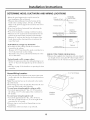
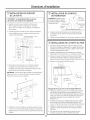
DETERMINE HOOD, DUCTWORK AND WIRING LOCATIONS
• Keep the wood support piece and its screws for
later h_stallation. Do not discard.
• Measure desired distance flom the bottom of the
hood to the cooking surf_ce, 24" rain. to 36 "Max.
Refer to the previous page if the access<n T duct cover
will be used.
• Use a level to draw a horizontal line indicating the
bottom of the hood.
• Use a level to draw the cooktop centerline location.
• Measure 15-3/8 "up flom the horizontal line fin the
bottom of the hood. Draw another horizontal line.
• Measure 18" up flom the line for the botton_ of the
hood, draw another horizontal line to indicate the
top of the hood.
FOR VERTICAL (Straight Up) DUCTING:
*If venting out the ceiling, extend the centerline
fbrward on the ceiling.
- Measure 6-7/8" flom drywall to mark centerline fin a
7-1/2" dia. duct hole on the ceiling.
- If drywall is not present, add drywall thickness to the
6-7/8" dimension.
Venting through a soffit or upper cabinet.
* Follow the same procedure ff_r ceiling ducting to cut
the 7-1/2" dia. hole through the top of the cabinet or
soffit.
* See Step 4, page 15 fin derails to cut opening fin duct
transition.
,, , _FOR CEILING
6-7/,8.... ',,/VENT DUCTING
benterllne/o vvall_X_- _
F== E,ectrica,
/
7-1/2" Dia.Hole
X
\ ,
i
"\\ =
,
"\\ i
"\,4, _Centerline
8" Min.Above
FOR , Topof Hood
Topof Hood
Wood
18" , Support
II 15-3/8"
| i Electrical
Bottomof Hood ,r II
,
i
,
,
i
FOR DUCTING THROUGH REAR WALL:
* Measure the supplied duct transition with any straight
run length of duct used, plus 90 oelbow height. Draw a
horizontal line on the wall intersecting the centerline.
House Wiring Location:
* Thej unction box is fastened to the back of the hood
on the right side. See illustrations fin hood knockout
locations.
Note: The j unction box can be relocated to the inside
top of the hood.
House wiring may enter thejtmcdon box fYom the rear
or the top of the hood at the right side.
To route house wiring through the ceiling or soffit:
- Cut a hole approximately 1" dia., 5-7/8" finward on
the ceiling, 11-1/8" to the right of the centerline fin.
30" models.
To route house wiring through the wall:
- Cut a hole approximately 1" dia., 10-1 / 16" down
fYom the top of the hood, 11-1/S" to the right of the
centerline fin 30" models.
* Remove top or rear knockout depending on your
installation.
* Install strain relief onto back or top of hood.
Knockout
Locations
, j ............11-1/8"for30" Models
11-1/8"for30"models
13

Installation instructions
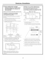
iNSTALL HOOD SUPPORT
IMPORTANT: Framing must be capable of
supporting 100 Ibs.
. i.ocate at least 2 vertical studs at the wood mounting
location by tapping drywall with a lmmmer or use a
stud finder.
* Center the supplied wood horizontal support, left to
right and below the marked line.
7" Min.Openingfor Ductworl<
Support
',,
,',
,',
\ Centerlineof
Installation
/
Space
*Drill 1/8" pilot holes thro ugh the support, drywall
and into the studs. Secure the support to 2 or more
vertical studs with supplied wood screws.
IMPORTANT: Screws must penetrate at least 1-1/2"
into vertical studs. Countersink screws into support.
i
i
i
l
/
/
Gap
* Install mounting screws in the center of the wood
support, 13-1/16 "fl'om the centerlin e. The screws
should protrude forward 1/4 'i This 1/4 "gap will
provide clearance to hang the hood.
INSTALL TRANSITION
IMPORTANT: Remove
shipping tape from
damper and check that
damper moves freely.
Remove
Shipping
Tapeon
Damper
Duct -- Topof
Transition Hood
* Place the transition piece over the hood exhaust.
Secure transition to hood with 4 screws provided.
e Use duct tape to seal the connection.
iNSTALL HOOD ONTO WALL
* Lif_ the hood and place over the wood support.
The top keyhole slots in the hood should engage
the protruding mounting screws. Allow the hood
to slide down into position.
* Pull house wiring through knockout at the rear or
the top of the hood.
. Check to be sure the hood is level and centered. The
arrow shaped c!ltotlt in the back of the hood allows
viewing the marked centerline.
*Remove cover flomj unction box.
14
24"
to
36"
Centerlineof \ _ __
Installation
Space
Drill Bottom Mounting Hole Locations
* Drill 1/8" pilot boles into the two lower mounting
boles. Enlarge the holes if they did not enter studs to
3/8". Tap anchors for wall fasteners into bottom boles.
Install screws by band into the fasteners to allow
anchors to expand against the wall. Remove screws.
* Using two large fiat washers (supplied), install wood
screws or wall fastener screws, loosely, into lower
mounting boles. Do not tighten.
* Check hood level. Tighten upper screws. Tighten
lower IIlotlnting sciews.
* For additional securiv, drive screws through the
original wood support screw boles in the back of
the hood.

Installation instructions
_Alternate Mounting Method
iNSTALL HOOD TO SOFFIT
OR BENEATH CABINETS
IMPORTANT: For additional support and to minimize
vibration during operation, we strongly recommend
that the hood also be secured to the back wall with
wall fasteners.
SKIP THiS STEP IF USING WALL MOUNTING
METHOD
IMPORTANT: Soffit framing must be capable
of supporting 100 Ibs.
When necessary, the hood may be installed so that
it is supported by the soffit.
* The soft=it should be constructed with 2 x 4's.
* Determine the installation location.
* Continue the centerline forward on the bottom
of the cabinet or soffit.
30" Models
"A" "B"
Centerline to Opening
Centerof Stud For Ductwork
14-1/2" 10-3/4"W x 8-7/16"D
Mounting screws must be secured to 2 x 4 studs
(Dim. "A") at locations shown in the above chart.
* Allow minimum opening (Dim. "B") to
accommodate the duct transition in the sofIlt.
t
24/8"
RearWall
I
I
4 3/8
' :T
(_ ',8-7/16"
......... _......... ] 1
I
TopView,FrontSide
2-9/16"
7-1/16"
f
2-1/4"
30"Models
_14-1/2'_1R_14-1/2 '_
t
2-3/8" 10-3/4"_
',8#/16"
I "
/
......... 4......... i ;
I
29-7/8"
TopView,FrontSide
*Drill four 1/8" pilot boles in locations shown.
- If mounting to the underside of a cabinet with
a recessed bottom, install shims to fill the gap.
i.........
: Cabinet
or
Soffit
1/4"Gap
EngageKeyholeSlots
andPushBack
to Wall
]
AddShims
If Bottom
Is Recessed
Back
Wall
* Drive mounting screws into the studs until they
protrude 1/4". Tiffs 1/4" gap will provide clearance
to engage the keyhole slots in the top of the hood.
* i,if_ hood onto mounting screws. Slide back against
the rear wall.
* Pull house wiring through the knockout at the rear
or the top of the hood.
* Tighten mounting screws.
Cuta 10-3/4"x 8-7/16"hole through bottomof soffit or cabinet for
duct transition as shown.
15

Installation instructions
iNSTALL CEiLiNG BRACKET
The ceiling bracket must be installed when the duct
cover is used to span 24" or more height above the
hood. The bracket will hold the decorative duct cover
in place at the top.
Note: The ceiling bracket is not required when using
only the ]2" section of the duct cover.
* Install the 2 small screws into the sides of the duct
bracket. Remove the screws. Pre-tapping the boles
will insure ease of final installation.
* Match center notch on the bracket to the centerline
on the wall and flush against the ceiling.
* Mark the 2 screw hole locations.
* Drill 1/8" pilot boles in marked bracket location.
* If pilot boles do not enter studs, enlarge the boles to
3/8" and install wall fastener anchors.
* Secure the bracket to the rear wall with wood screws
and washers. Use wall anchors if needed.
Note: Bracket has 2sets of holes. Uselarger hobs for wall
fasteners or wood screws with washers. Usesmaller holes for
wood screws with washers.
Install
CeilingBracket_ ' i4! "-.
WhenDuct ,'"
Coveris
UsedtoSpan
24"orMore
See Step 9
to Install
Duct Cover
CONNECT DUCTWORK
* Push duct over the end of the transition until it
reaches the stop tabs.
* Install ductwork, making connections in direction of
airflow as illustrated.
* Secure joints in ductwork with sheetmeml screws.
* Wrap all duct joints with duct rope for an airdght
seal.
* Use duct rope to seal the flange connection.
HouseDuctworl<
DuctTape
OverSeam
andScrew
DuctTape
Onlyfor Proper
Operation
ofDamper /_//
f
DuctTape J
OverFlange
_Air
Flow
Screw
Ductworl<
Duct
Stops
\
sition
ACAUTION"
[] Do not use sheet metal
screws at the transition to duct_,vork connection.
Doing so will prevent proper damper operations.
Seal connection with rope only.
16

Installation instructions
INSTALL MOTOR
• Align and engage tile
slots in tile blower
assembly to the 3 books
at the rear of the
exhaust opening°
MotorHook_
• Rotate motor upwards r_-_
_1ooo oo i_
until it aligns with. th.e ,A_r_"_L
attacbmdK screw
location.
• Sectlre the illotoi to
attachment bracket
at the front of the
opening with washer
and screw provided. S__
//ylx_
the mating hood connector. See /!_i_ \ :
connector location. Touch the _
hood to locate and make tile /
/
COllllectioll. (_
IMPORTANT: Hold tile _x_ __L_f_
connector so tlle two square_'_J_ _--]--O_.L_
corner terminals are at tile top__ you \_-_ J
position tile connector to plug it in.
CONNECT ELECTRICAL
Verify that power is turned off at the source.
AWARNING"
[] Ifhouse wiring is not
2-wire with a ground wire, a ground must be provided
by the insmllm: When house wiring is aluminmn, be
sure to use U.L. approved and-oxidant colnpound
and aluminmn-to-copper connectors.
/ -o .............. .__
A Remove C InsertPower ,_"_,
JunctionBox ConduitThru i'a_(" ._,_
Cover StrainRelief '\ "%_"_t;_ I /,
andTighten _ ,,___.A..__y_
.... " .... . . _/
IIDi I II i_ ...........White
Ground--.._I I Z_.J /_glacl<
B CheckThatWhite,Blackand ['_/ff _ [
GreenHoodWires AreThreadedIt_/"!_,,,/'_g_ _I
ThruSmallHolein Bracket _ J
D UseULListedWire Nuts
* Use wire nuts to connect incoming ground to green,
white to white and black to black.
e Push wires intojmlction box and replace cover.
Be sure wires are not pinched.
17
INSTALL DUCT COVERS
To install the 12 "duct cover alone:
* Place tlle 12" section of tlle decorative duct cover on
top of tlle hood.
e Secure tile cover to tile top of tile hood with 4 screws
provided.
To install the 2-piece duct cover:
* Place tlle 2-piece duct cover on top of tile hood.
* Secure tile bottom cover to the top of the hood with
4 screws provided. See illustration, page 16.
* Extend tlle inside section upwards to meet tlle
ceiling and ceiling bracket.
* Secure the duct cover to the bracket with the 2 small
Phillips screws provided.
INSTALL FILTER SUPPORT
* Tip filter support into tile rear of tile hood.
* Insert support robs into the slots at the rear of
tile hood.
/
/
¢
/
InsertTabsIntoSlots
/
* Secure the support to the hood with screws as shown.

Installation instructions
iNSTALL FILTERS
* Remove protective film covering the filters.
* Insert the filter into the "C" clips mounted to the top
of the vertical flont panel.
* Tap the filter against one side to align with outside
opening.
* Pull the filter down into the lower slots at the bottom
of the filter support.
Junction
Box
"C"Clip
Filters
Filter
Support
J
*To remove the filters, grasp the handle, push the
filter up and pull forward.
FINALIZE iNSTALLATiON
* Refer to the operating instructions to test all
contIols.
18

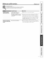
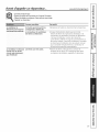
Beforeyou call forservice... C ,,,/iances.com
Troubleshooting tips
Save time and money! Review the charts on the following
pages first and you may not need to call for service.
Possible Causes What ToDo
Fandoes notoperate A fuse may be blown or a * Replace fuse or reset circuit breaker:
when the switch is on circuit breaker tripped.
Fanfails to circulate air
or movesair slower than
normal
The blower connector is loose
or not plugged into its mating
connector.
Excessively soiled filters.
* Disconnect power to the unit. Remove the filters
and look up at the blowei: If the blower connector
plug is loose or you see the connector dangling,
the installer failed to plug it in securely. Although it
is a blind connection, it is easy to plug in. See the
Installation Instructions in this manual for the plug
]ocadon and how to plug the connector in.
* Remove the filters, clean if necessary and replace
them. If cleaning and replacing the filters does not
correct the problem, call for service.
19

m
-i
_w
ML
m
m
w
Notes.
2O
La page est en cours de chargement...
La page est en cours de chargement...
La page est en cours de chargement...
La page est en cours de chargement...
La page est en cours de chargement...
La page est en cours de chargement...
La page est en cours de chargement...
La page est en cours de chargement...
La page est en cours de chargement...
La page est en cours de chargement...
La page est en cours de chargement...
La page est en cours de chargement...
La page est en cours de chargement...
La page est en cours de chargement...
La page est en cours de chargement...
La page est en cours de chargement...
La page est en cours de chargement...
La page est en cours de chargement...
La page est en cours de chargement...
La page est en cours de chargement...
La page est en cours de chargement...
La page est en cours de chargement...
La page est en cours de chargement...
La page est en cours de chargement...
La page est en cours de chargement...
La page est en cours de chargement...
La page est en cours de chargement...
La page est en cours de chargement...
-
 1
1
-
 2
2
-
 3
3
-
 4
4
-
 5
5
-
 6
6
-
 7
7
-
 8
8
-
 9
9
-
 10
10
-
 11
11
-
 12
12
-
 13
13
-
 14
14
-
 15
15
-
 16
16
-
 17
17
-
 18
18
-
 19
19
-
 20
20
-
 21
21
-
 22
22
-
 23
23
-
 24
24
-
 25
25
-
 26
26
-
 27
27
-
 28
28
-
 29
29
-
 30
30
-
 31
31
-
 32
32
-
 33
33
-
 34
34
-
 35
35
-
 36
36
-
 37
37
-
 38
38
-
 39
39
-
 40
40
-
 41
41
-
 42
42
-
 43
43
-
 44
44
-
 45
45
-
 46
46
-
 47
47
-
 48
48


GE CV936M1SS Le manuel du propriétaire
- Catégorie
- Hottes
- Taper
- Le manuel du propriétaire
dans d''autres langues
- English: GE CV936M1SS Owner's manual
Documents connexes
Autres documents
-
Blomberg BCHP30100SS Manuel utilisateur
-
-
Beko CHP30100SS Manuel utilisateur
-
Forno FRHWM5029-30HB Le manuel du propriétaire
-
Forno FRHWM502936HB Le manuel du propriétaire
-
 ALASKA ELECTRIC SA-398WC Manuel utilisateur
-
Electrolux PLHV36W7CC Guide d'installation
-
 GE Monogram ZVTSFSS Guide d'installation
-
GE Profile GEJV936DSS Mode d'emploi
-

