Miller KJ164358 Le manuel du propriétaire
- Catégorie
- Système de soudage
- Taper
- Le manuel du propriétaire
Ce manuel convient également à

OM-1586
155
318P
June
1998
Processes
~
MIG
(GMAW)
Welding
Pulsed
MIG
(GMAW-P)
Flux
Cored
(FCAW)
Welding
SS-64M
SwingarcTM
Miller
The
Power
ofBlue.
Description
Wire
Feeder
(Use
with
CC/CV
Power
Sources)
D~
Visit
our
website
at
www.MillerWetdz.com
12
and
16
Foot
OWNERS
MANUAL

U
From
Miller
to
You
I
Thank
you
and
congratulations
on
choosing
Miller.
Nowi
you
can
get
the
job
done
and
get
it
done
right.
We
know
you
dont
have
time
to
do
it
any
other
way.
Thats
why
when
Niels
Miller
first
started
building
arc
welders
in
1929,
he
made
sure
his
products
offered
long-lasting
value
and
superior
quality.
Like
you,
his
customers
couldnt
afford
anything
less.
Miller
products
had
to
be
more
than
the
best
they
could
be.
They
had
to
be
the
best
you
could
buy.
Today,
the
people
that
build
and
sell
Miller
products
continue
the
tradition.
Theyre
just
as
committed
to
providing
equipment
and
service
that
meets
the
high
standards
of
quality
and
value
established
in
1929.
This
Owners
Manual
is
designed
to
help
you
get
the
most
out
of
your
Miller
products.
Please
take
time
to
read
the
Safety
precautions.
They
will
help
you
protect
yourself
against
potential
hazards
on
the
worksite.
Weve
¶~f~Jfl1i1J1fl1~
iIh(iUIIIW
REGISTERED
QUALITY
SYSTEM
Miller
is
the
first
welding
equipment
manufacturer
in
the
U.S.A.
to
be
registered
to
the
ISO
9001
Quality
System
Standard.
Working
as
bard
asyoudo
.
power
source
Tram
MlltB~
Is
backed
by
the
must
hassle-tree
wepranty
in
the
blIsIlIesS:
made
installation
and
operation
quick
and
easy.
With
Miller
you
can
count
on
years
of
reliable
service
with
proper
maintenance.
And
if
for
some
reason
the
unit
needs
repair,
theres
a
Troubleshooting
section
that
will
help
you
figure
out
what
the
problem
is.
The
parts
list
will
then
help
you
to
decide
which
exact
part
you
may
need
to
fix
the
problem.
Warranty
and
service
information
for
your
particular
model
are
also
provided.
~
Miller
Electric
manufactures
a
full
line
of
welders
and
welding
related
equipment.
For
information
on
other
quality
Miller
products,
contact
your
local
Miller
distributor
to
receive
the
latest
full
line
catalog
or
individual
catalog
sheets.
To
locate
your
nearest
distributor
call
1-800-4-A-Miller.
Miller
offers
a
Technical
Manual
which
provides
more
detailed
service
and
parts
information
for
your
unit
To
obtain
a
Technical
Manual,
contact
your
local
distributor
Your
distributor
can
also
supply
you
with
Welding
Process
Manuals
such
as
SMAW,
GTAW.
GMAW,
and
GMAW-P,
L

OM-1
586P
TABLE
OF
CONTENTS
SECTION
1
-
SAFETY
PRECAUTIONS
-
READ
BEFORE
USING
1
1-1.
Symbol
Usage
1
1
-2.
Arc
Welding
Hazards
1
1-3.
Additional
Symbols
for
Installation,
Operation,
and
Maintenance
3
1-4.
Principal
Safety
Standards
3
1-5.
EMF
Information
4
SECTION
1
-
CONSIGNES
DE
SECURITE
-
LIRE
AVANT
UTILISATION
5
1-1.
Signification
des
symboles
5
1-2.
Dangers
relatifs
au
soudage
a
arc
5
1-3.
Dangers
supplØmentaires
en
relation
avec
Iinstallation,
le
fonctionnement
et
Ia
maintenance
7
1-4.
Principales
normes
de
sØcuritØ
8
1-5.
Information
sur
les
champs
ØlectromagnØtiques
8
SECTION
2
-
INTRODUCTION
9
2-1.
Specifications
9
SECTION
3
-
INSTALLATION
9
3-1.
Installing
Swivel
Into
Pipe
Post
9
3-2.
Installing
Boom
And
Reel
Support
10
3-3.
Installing
Wire
Guide
Extension
10
3-4.
Adjusting
Control
Tilt
Bracket
10
3-5.
Equipment
Connection
Diagrarrt
11
3-6.
Connecting
Weld
Cables
And
Gas
Hoses
12
3-7.
Control
Box
Connections
13
3-8.
14-Pin
Plug
Information
13
3-9.
Motor
Start
Control
14
3-10.
Removing
Safety
Collar
And
Adjusting
Boom
14
3-11.
Gun
Recommendation
Table
15
3-12.
Wire
Type,
Size,
And
Feed
Speed
Capability
Table
15
3-13.
Installing
And
Threading
Welding
Wire
16
SECTION
4
-
OPERATION
17
4-1.
Operational
Terms
17
4-2.
Pulse
Welding
Terms
17
4-3.
Front
Panel
Controls
18
4-4.
Side
And
Rear
Panel
Controls
18
SECTION
5
-
SETFING
SEQUENCE
PARAMETERS
19
5-1.
Sequence
Parameters
In
A
Program
19
SECTION
6-
SETFING
DUAL
SCHEDULE
PARAMETERS
20
6-1.
Selecting
Dual
Schedule
Pair
20
6-2.
Dual
Schedule
Switch
Diagrams
21
SECTION
7
-
USING
THE
OPTIONAL
DATA
CARU
22
7-1.
Data
Card
Terms
22
7-2.
Installing
Data
Card
22
7-3.
Card
Displays
23
SECTION
8-
SYSTEM
SETUP
24
8-1.
System
Setup
Display
Parameters
24
SECTION
9-
STANDARD
PULSE
WELDING
PROGRAMS
25
9-1.
Program
1
-
Steel
25
9-2.
Program
2
-
Steel
25
9-3.
Program
3
-
Steel
25
9-4.
Program
4
-
Steel
25
9-5.
Program
5
-
Stainless
26
9-6.
Program
6
-
Stainless
26
9-7.
Program
7
-
Nickel
Alloy
26
9-8.
Program
8
-
Silicon
Bronze
26
SECTION
10-
TEACH
POINTS
27
10-1.
Teach
Using
15
Points
27
10-2.
Teach
Using
4
Points
28
10-3.
Redefining
Teach
Points
29
SECTION
11
-
MAINTENANCE
AND
TROUBLESHOOTING
31
11-1.
Routine
Maintenance
31
11-2.
Error
Displays
32
11-3.
Troubleshooting
33
SECTION
12
-
ELECTRICAL
DIAGRAM
34
SECTION
13-
PARTS
LIST
.36
OPTIONS
AND
ACCESSORIES
WARRANTY


SECTION
1
-
SAFETY
PRECAUTIONS
-
READ
BEFORE
USING
som
nd_5/97
1-1.
Symbol
Usage
a
A
Marks
a
special
safety
message.
lET
Means
Note~
not
safety
related.
1-2
Arc
Welding
Hazards
A
The
symbols
shown
below
are
used
throughout
this
manual
to
call
attention
to
and
identify
possible
hazards.
When
you
see
the
symbol,
watch
out,
and
followthe
related
instructions
to
avoid
the
hazard.
The
safety
information
given
below
is
only
a
summary
of
the
more
complete
safety
information
found
in
the
Safety
Standards
listed
in
Section
1
-4.
Read
and
follow
all
Safety
Standards.
A
Only
qualified
persons
should
install,
operate,
maintain,
and
repair
this
unit.
A
During
operation,
keep
everybody,
especially
children,
away.
ELECTRIC
SHOCK
can
kill.
Touching
live
electrical
parts
can
cause
fatal
shocks
or
severe
burns.
The
electrode
and
work
circuit
is
electrically
live
whenever
the
output
is
on.
The
input
power
circuit
and
machine
internal
circuits
are
also
live
when
power
is
on.
In
semiautomatic
or
automatic
wire
welding,
the
wire,
wire
reel,
drive
roll
housing,
and
all
metal
parts
touching
the
welding
wire
are
electrically
live.
Incorrectly
installed
or
improperly
grounded
equipment
is
a
hazard.
Do
not
touch
live
electrical
parts.
Wear
dry,
hole-free
insulating
gloves
and
body
protection.
Insulate
yourself
from
work
and
ground
using
dry
insulating
mats
or
covers
big
enough
to
prevent
any
physical
contact
with
the
work
or
ground.
Do
not
use
AC
output
in
damp
areas,
if
movement
is
confined,
or
if
there
is
a
danger
of
falling.
Use
AC
output
ONLY
if
required
for
the
welding
process.
If
AC
output
is
required,
use
remote
output
control
if
present
on
unit.
Disconnect
input
power
or
stop
engine
before
installing
or
servicing
this
equipment.
Lockout/tagout
input
power
according
to
OSHA
29
CFR
191
0.147
(see
Safety
Standards).
Properly
install
and
ground
this
equipment
according
to
its
Owners
Manual
and
national,
state,
and
local
codes.
Always
verify
the
supply
ground
-
check
and
be
sure
that
input
power
cord
ground
wire
is
properly
connected
to
ground
terminal
in
disconnect
box
or
that
cord
plug
is
connected
to
a
properly
grounded
receptacle
outlet.
When
making
input
connections,
attach
proper
grounding
conductor
first
-
double-check
connections.
Frequently
inspect
input
power
cord
for
damage
or
bare
wiring
-
replace
cord
immediately
if
damaged
-
bare
wiring
can
kill.
Turn
off
all
equipment
when
not
in
use.
Do
not
use
worn,
damaged,
undersized,
or
poorly
spliced
cables.
Do
not
drape
cables
over
your
body.
This
group
of
symbols
means
Warning!
Watch
Out!
possible
ELECTRIC
SHOCK,
MOVING
PARTS,
and
HOT
PARTS
hazards.
Consult
symbols
and
related
instructions
below
for
necessary
actions
to
avoid
the
hazards.
It
earth
grounding
of
the
workpiece
is
required,
ground
it
directly
with
a
separate
cable
-
do
not
use
work
clamp
or
work
cable.
Do
not
touch
electrode
if
you
are
in
contact
with
the
work,
ground,
or
another
electrode
from
a
different
machine.
Use
only
well-maintained
equipment.
Repair
or
replace
damaged
parts
at
once.
Maintain
unit
according
to
manual.
Wear
a
safety
harness
if
working
above
floor
level.
Keep
all
panels
and
covers
securely
in
place.
Clamp
work
cable
with
good
metal-to-metal
contact
to
workpiece
or
worktable
as
near
the
weld
as
practical.
Insulate
work
clamp
when
not
connected
to
workpiece
to
prevent
contact
with
any
metal
object.
Do
not
connect
more
than
one
electrode
or
work
cable
to
any
single
weld
output
terminal.
SIGNIFICANT
DC
VOLTAGE
exists
after
removal
of
input
power
on
inverters.
Turn
Off
inverter,
disconnect
input
power,
and
discharge
input
capacitors
according
to
instructions
in
Maintenance
Section
before
touching
any
parts.
FUMES
AND
GASES
can
be hazardous
L_.
IIV
Welding
produces
fumes
and
gases.
Breathing
-~-~
~
these
fumes
and
gases
can
be
hazardous
to
your
health.
Keep
your
head
out
of
the
fumes.
Do
not
breathe
the
fumes.
If
inside,
ventilate
the
area
and/or
use
exhaust
at
the
arc
to
remove
welding
fumes
and
gases.
If
ventilation
is
poor,
use
an
approved
air-supplied
respirator.
Read
the
Material
Safety
Data
Sheets
(MSDSs)
and
the
manufacturers
instructions
for
metals,
consumables,
coatings,
cleaners,
and
degreasers.
Work
in
a
confined
space
only
if
it
is
well
ventilated,
or
while
wearing
an
air-supplied
respirator.
Always
have
a
trained
watch-
person
nearby.
Welding
fumes
and
gases
can
displace
air
and
lower
the
oxygen
level
causing
injury
or
death.
Be
sure
the
breathing
air
is
safe.
Do
not
weld
in
locations
near
degreasing,
cleaning,
or
spraying
operations.
The
heat
and
rays
of
the
arc
can
react
with
vapors
to
form
highly
toxic
and
irritating
gases.
Do
not
weld
on
coated
metals,
such
as
galvanized,
lead,
or
cadmium
plated
steel,
unless
the
coating
is
removed
from
the
weld
area,
the
area
is
well
ventilated,
and
if
necessary,
while
wearing
an
air-supplied
respirator.
The
coatings
and
any
metals
containing
these
elements
can
give
off
toxic
fumes
if
welded.
Means
Warning!
Watch
Out!
There
are
possible
hazards
with
this
procedure!
The
possible
hazards
are
shown
in
the
adjoining
symbols.
.
.
OM-1586
Page
1

Arc
rays
from
the
welding
process
produce
intense
visible
and
invisible
(ultraviolet
and
infrared)
rays
that
can
burn
eyes
and
skin.
Sparks
fly
off
from
the
weld.
Wear
awelding
helmet
fitted
with
a
proper
shade
offilterto
protect
your
face
and
eyes
when
welding
or
watching
(see
ANSI
249.1
and
Z87.1
listed
in
Safety
Standards).
Wear
approved
safety
glasses
with
side
shields
under
your
helmet.
Use
protective
screens
or
barriers
to
protect
others
from
flash
and
glare;
warn
others
not
to
watch
the
arc.
Wear
protective
clothing
made
from
durable,
flame-resistant
material
(leather
and
wool)
and
foot
protection.
WELDING
can
caUsefireorexplosion.
Welding
on
closed
containers,
such
as
tanks,
drums,
or
pipes,
can
causethem
to
blow
up.
Sparks
can
fly
off
from
the
welding
arc.
The
flying
sparks,
hot
workpiece,
and
hot
equipment
can
cause
fires
and
burns.
Accidental
contact
of
electrode
to
metal
objects
can
cause
sparks,
explosion,
overheating,
or
fire.
Check
and
be
surethe
area
is
safe
before
doing
any
welding.
Protect
yourself
and
others
from
flying
sparks
and
hot
metal.
Do
not
weld
where
flying
sparks
can
strike
flammable
material.
Remove
all
flammables
within
35
ft
(10.7
m)
of
the
welding
arc.
If
this
is
not
possible,
tightly
cover
them
with
approved
covers.
Be
alert
that
welding
sparks
and
hot
materials
from
welding
can
easily
go
through
small
cracks
and
openings
to
adjacent
areas.
Watch
for
fire,
and
keep
a
fire
extinguisher
nearby.
Be
aware
that
welding
on a
ceiling,
floor,
bulkhead,
or
partition
can
cause
fire
on
the
hidden
side.
Do
not
weld
on
closed
containers
such
as
tanks,
drums,
or
pipes,
unless
they
are
properly
prepared
according
to
AWS
F4.1
(see
Safety
Standards).
Connect
work
cable
to
the
work
as
close
to
the
welding
area
as
practical
to
prevent
welding
current
from
traveling
long,
possibly
unknown
paths
and
causing
electric
shock
and
fire
hazards.
Do
not
use
welder
to
thaw
frozen
pipes.
Remove
stick
electrode
from
holder
or
cut
off
welding
wire
at
contact
tip
when
not
in
use.
Wear
oil-free
protective
garments
such
as
leather
gloves,
heavy
shirt,
cuffless
trousers,
high
shoes,
and
a
cap.
Remove
any
combustibles,
such
as
a
butane
lighter
or
matches,
from
your
person
before
doing
any
welding.
FLYING
METAL
can
injure
eyes.
Welding,
chipping,
wire
brushing,
and
grinding
cause
sparks
and
flying
metal.
As
welds
cool,
they
can
throw
off
slag.
Wear
approved
safety
glasses
with
side
shields
even
under
your
welding
helmet.
BUILDUP
OF
GAS
can
injure
or
kill
Shut
off
shielding
gas
supply
when
not
in
use.
Always
ventilate
confined
spaces
or
use
approved
air-supplied
respirator.
HOT.
PARTS
can
cause
severe
burns.
Do
not
touch
hot
parts
bare
handed.
Allow
cooling
period
before
working
on
gun
or
torch.
MAGNETIC
FIELDS
can
affect
pacemakers.
Pacemaker
wearers
keep
away.
Wearers
should
consult
their
doctor
before
going
near
arc
welding,
gouging,
or
spot
welding
operations.
NOISE
can
damage
hearing.
Noise
from
some
processes
or
equipment
can
damage
hearing.
Wear
approved
ear
protection
if
noise
level
is
high.
Shielding
gas
cylinders
contain
gas
under
high
pressure.
If
damaged,
a
cylinder
can
explode.
Since
gas
cylinders
are
normally
part
of
the
welding
process,
be
sure
to
treat
them
carefully.
Protect
compressed
gas
cylinders
from
excessive
heat,
mechanical
shocks,
slag,
open
flames,
sparks,
and
arcs.
Install
cylinders
in
an
upright
position
by
securing
to
a
stationary
support
or
cylinder
rack
to
prevent
falling
or
tipping.
Keep
cylinders
away
from
any
welding
or
other
electrical
circuits.
Never
drape
a
welding
torch
over
a
gas
cylinder.
Never
allow
a
welding
electrode
to
touch
any
cylinder.
Never
weld
on
a
pressurized
cylinder
-
explosion
will
result.
Use
only
correct
shielding
gas
cylinders,
regulators,
hoses,
and
fittings
designed
for
the
specific
application;
maintain
them
and
associated
parts
in
good
condition.
Turn
face
away
from
valve
outlet
when
opening
cylinder
valve.
Keep
protective
cap
in
place
overvalve
except
when
cylinder
is
in
use
or
connected
for
use.
Read
and
follow
instructions
on
compressed
gas
cylinders,
associated
equipment,
and
CGA
publication
P-i
listed
in
Safety
Standards.
ARC
RAYS
can
burn
eyes
and
skin
CYLINDERS
can
explode
if
damaged.
.
.
OM-1586
Page
2

FIRE
OR
EXPLOSION
hazard.
Do
not
install
or
place
unit
on,
over,
or
near
combustible
surfaces.
Do
not
install
unit
near
flammables.
Do
not
overload
building
wiring
-
be
sure
power
supply
system
is
properly
sized,
rated,
and
protected
to
handle
this
unit.
FALLiNG
UNIT
can
cause
injury
Use
lifting
eye
to
lift
unit
only,
NOT
running
gear,
gas
cylinders,
or
any
other
accessories.
Use
equipment
of
adequate
capacity
to
lift
and
support
unit.
If
using
lift
forks
to
move
unit,
be
sure
forks
are
long
enough
to
extend
beyond
opposite
side
of
unit.
OVERUSE
can
cause
OVERHEATING
Allow
cooling
period;
follow
rated
duty
cycle.
Reduce
current
or
reduce
duty
cycle
before
starting
to
weld
again.
Do
not
block
or
filter
airflow
to
unit.
STATIC
(ESD)
can
damage
PC
boards
Put
on
grounded
wrist
strap
BEFORE
handling
boards
or
parts.
Use
proper
static-proof
bags
and
boxes
to
store,
move,
or
ship
PC
boards.
MOVING
PARTS
can
cause
injury
Keep
away
from
moving
parts.
Keep
away
from
pinch
points
such
as
drive
rolls.
WELDING
WIRE
can
cause
injury.
Do
not
press
gun
trigger
until
instructed
to
do
so.
Do
not
point
gun
toward
any
part
of
the
body,
other
people,
or
any
metal
when
threading
welding
wire.
1-4.
Principal
Safety
Standards
Safety
in
Welding
and
Cutting,
ANSI
Standard
Z49.1,from
American
Welding
Society,
550
N.W.
LeJeune
Rd,
Miami
FL
33126
Safety
and
Health
Standards,
OSHA
29
CFR
1910,
from
Superinten
dent
of
Documents,
U.S.
Government
Printing
Office,
Washington,
D.C.
20402.
Recommended
Safe
Practices
for
the
Preparation
for
Welding
and
Cutting
of
Containers
That
Have
Held
Hazardous
Substances,
American
Welding
Society
Standard
AWS
F4.1,
from
American
Welding
Society,
550
N.W.
LeJeune
Rd,
Miami,
FL
33126
National
Electncal
Code,
NFPA
Standard
70,
from
National
Fire
Protection
Association,
Batterymarch
Park,
Quincy,
MA
02269.
MOVING
PARTS
can
cause
injury
Keep
away
from
moving
parts
such
as
fans.
Keep
all
doors,
panels,
covers,
and
guards
closed
and
securely
in
place.
HF.
RADIATION
can
causeinterference.
High-frequency
(HF.)
can
interfere
with
radio
navigation,
safety
services,
computers,
and
communications
equipment.
Have
only
qualified
persons
familiar
with
electronic
equipment
perform
this
installation.
The
user
is
responsible
for
having
a
qualified
electrician
promptly
correct
any
interference
problem
resulting
from
the
installation.
If
notified
by
the
FCC
about
interference,
stop
using
the
equipment
at
once.
Have
the
installation
regularly
checked
and
maintained.
Keep
high-frequency
source
doors
and
panels
tightly
shut,
keep
spark
gaps
at
correct
setting,
and
use
grounding
and
shielding
to
minimize
the
possibility
of
interference.
ARC
WELDING
can
cause
interference
Electromagnetic
energy
can
interfere
with
sensitive
electronic
equipment
such
as
computers
and
computer-driven
equipment
such
as
robots.
Be
sure
all
equipment
in
the
welding
area
is
electromagnetically
compatible.
To
reduce
possible
interference,
keep
weld
cables
as
short
as
possible,
close
together,
and
down
low,
such
as
on
the
floor.
Locate
welding
operation
100
meters
from
any
sensitive
elec
tronic
equipment.
Be
sure
this
welding
machine
is
installed
and
grounded
according
to
this
manual.
If
interference
still
occurs,
the
user
must
take
extra
measures
such
as
moving
the
welding
machine,
using
shielded
cables,
using
line
filters,
or
shielding
the
work
area.
Safe
Handling
of
Compressed
Gases
in
Cylinders,
CGA
Pamphlet
P-i,
from
Compressed
Gas
Association,
1235
Jefferson
Davis
Highway,
Suite
501,
Arlington,
VA
22202.
Code
for
Safety
in
Welding
and
Cutting,
CSA
Standard
Wi
17.2,
from
Canadian
Standards
Association,
Standards
Sales,
178
Rexdale
Boulevard,
Rexdale,
Ontario,
Canada
M9W
1
R3.
Safe
Practices
For
Occupation
And
Educational
Eye
And
Face
Protection,
ANSI
Standard
Z87.1
,from
American
National
Standards
Institute,
1430
Broadway,
New
York,
NY
10018.
Cutting
And
Welding
Processes,
NFPA
Standard
51
B,
from
National
Fire
Protection
Association,
Batterymarch
Park,
Quincy,
MA
02269.
1
-3~
Additional
Symbols
For
Installation,
Operation,
And
Maintenance
OM-1586
Page
3

1-5
EMF
Information
Considerations
About
Welding
And The
Effects
Of
Low
Frequency
Electric
And
Magnetic
Fields
Welding
current,
as
it
flows
through
welding
cables,
will
cause
electro
magnetic
fields.
There
has
been
and
still
is
some
concern
about
such
fields.
However,
after
examining
more
than
500
studies
spanning
17
years
of
research,
a
special
blue
ribbon
committee
of
the
National
Research
Council
concluded
that:
The
body
of
evidence,
in
the
committees
judgment,
has
not
demonstrated
that
exposure
to
power-
frequency
electric
and
magnetic
fields
is
a
human-health
hazard.
However,
studies
are
still
going
forth
and
evidence
continues
to
be
examined.
Until
the
final
conclusions
of
the
research
are
reached,
you
may
wish
to
minimize
your
exposure
to
electromagnetic
fields
when
welding
or
cutting.
To
reduce
magnetic
fields
in
the
workplace,
use
the
following
procedures:
1.
Keep
cables
close
together
by
twisting
or
taping
them.
2.
Arrange
cables
to
one
side
and
away
from
the
operator.
3.
Do
not
coil
or
drape
cables
around
your
body.
4.
Keep
welding
power
source
and
cables
as
far
away
from
opera
tor
as
practical.
5.
Connect
work
clamp
to
workpiece
as
close
to
the
weld
as
possible.
About
Pacemakers:
Pacemaker
wearers
consult
your
doctor
first,
If
cleared
by
your
doctor,
then
following
the
above
procedures
is
recommended.
OM-1586
Page
4

SECTION
1
-
CONSIGNES
DE
SECURITE
-
LIRE
AVANT
UTI
LISATION
Signification
des
symboles
Signifie
Mise
en
garde!
Soyez
vigilant!
Cette
procedure
prØsente
des
risques
de
danger!
Ceux-ci
sont
identifies
par
des
symboles
adjacents
aux
directives.
1-2.
DangersrØlatifs
au
soudage
a
Iarc
A
Les
symboles
prØsentØs
ci-aprŁs
sont
utilisØs
tout
au
long
du
present
manuel
pour
attirer
votre
attention
et
identifier
les
risques
de
danger.
Lorsque
vous
voyez
un
symbole,
soyez
vigilant
et
suivez
les
directives
mentionnØes
afin
dØviter
tout
danger.
Les
consignes
de
sØcuritØ
prØsentØes
ci-aprŁs
ne
font
que
rØsumer
linformation
contenue
dans
les
normes
de
sØcuritØ
ØnumØrØes
a
Ia
section
1-4
Veuillez
lire
et
respecter
toutes
ces
normes
de
sØcuritØ.
A
Linstallation,
lutilisation,
lentretien
et
les
reparations
ne
dol
vent
Łtre
confiØs
qu
des
personnes
qualifiØes.
A
Au
coursde
lutilisation,
tenirtoute
personne
a
lØcartet
plus
par
ticuliŁrement
les
enfants.
UN
CHOC
ELECTRIQUE
peut
tuer
Un
simple
contact
avec
des
piŁces
Ølectriques
peut
provoquer
une
electrocution
ou
des
blessures
graves.
LØlectrode
et
le
circuit
de
soudage
sont
sous
tension
des
que
lappareil
est
sur
ON.
Le
circuit
dentrŁe
et
les
circuits
internes
de
lappareil
sont
egalement
sous
tension
a
ce
moment-l.
En
soudage
semi-automatique
ou
automatique,
le
f
ii,
le
dØvidoir,
le
logement
des
galets
dentrainement
et
es
piŁces
mØtalliques
en
contact
avec
le
fil
de
soudage
sont
sous
tension.
Des
matŁriels
mal
installŁs
ou
mal
mis
a
Ia
terre
prŁsentent
un
danger.
Ne
jamais
toucher
es
piŁces
Łlectriques
sous
tension.
Porter
des
gants
et
des
vŒtements
de
protection
secs ne
comportant
pas
de
trous.
Sisoler
de
Ia
piŁce
et
de
Ia
terre
au
moyen
de
tapis
ou
dautres
moyens
isolants
suffisamment
grands
pour
empŁcher
le
contact
phy
sique
Łventuel
avec
Ia
piŁce
ou
a
terre.
Ne
pas
se
servir
de
source
Łlectrique
courant
electrique
dans
les
zones
humides,
dans
les
endroits
confines
ou
l
ou on
risque
de
tomber.
Se
servir
dune
source
electnque
courant
Łlectrique
UNIQUEMENT
Si
le
procŁdØ
de
soudage
le
demande.
Si
Iutilisation
dune
source
Łlectrique
courant
Łlectrique
savŁre
nØces
saire,
se
servir
de
Ia
fonction
de
tØlØcommande
Si
Iappareil
en
est
ŁquipØ.
Couperlalimentation
ou
arrŒter
le
moteuravantde
procŁder
linstal
lation,
a
Ia
reparation
ou
a
lentretien
de
lappareil.
DØverrouiller
Ialimentation
selon
Ia
norme
OSHA
29
CFR
191
0.147
(voir
normes
de
sØcuritŁ).
Installeretmettrelaterre
correctement
cet
appareil
conformŁment
son
manuel
dutilisation
et
aux
codes
nationaux,
provinciaux
et
municipaux.
Toujours
verifier
Ia
terre
du
cordon
datimentation
-
Verifier
et
sassu
rer
que
le
fll
de
terre
du
cordon
dalimentation
est
bien
raccordŁ
a
Ia
borne
deterre
du
sectionneur
ou
que
Ia
fiche
du
cordon
est
raccordØe
a
une
prise
correctement
mise
a
Ia
terre.
En
effectuant
les
raccordements
dentrØe
fixer
dabord
le
conducteur
de
mise
a
Ia
terre
appropriŁ
et
contre-vØrifier
les
connexions.
Verifier
frequemment
le
cordon
dalimentation
pour
voir
siI
nest
pas
endommagŁ
ou
dŁnudŁ
-
remplacer
le
cordon
immŁdiatement
sil
est
endommage
-
un
cable
dŁnudØ
peut
provoquer
une
electrocution.
Mettre
lappareil
hors
tension
quand
on
ne
Iutilise
pas.
Ne
pas
utiliser
des
cables
uses,
endommages,
de
grosseur
insuffi
sante
ou
mal
ŁpissØs.
Ne
pas
enrouler
les
cables
autour
du
corps.
Si
Ia
piŁce
soudØedoitŒtre
mise
a
laterre,
lefairedirectementavec
un
cable
distinct
-
ne
pas
utiliser
le
connecteur
de
piŁce
ou
le
cable
de
retour.
scm
ndfre
5/97
Ce
groupe
de
symboles
signifie
Mise
en
garde
!
Soyez
vigilant
lIy
a
des
risques
de
danger
relies
aux
CHOCS
ELECTRIQUES,
aux
PIECES
EN
MOUVEMENTetaux
PIECESCHAUDES.
Reportez-vousauxsymboles
etauxdirectivesci-dessous
afin
de
connaitre
les
mesures
a
prendre
pour
Øviter
tout
danger.
Ne
pas
toucher
lŁlectrode
quand
on
est
en
contact
avec
Ia
piŁce,
Ia
terre
ou
une
electrode
provenant
dune
autre
machine.
Nutiliser
quun
materiel
en
bon
Łtat.
RØparer
ou
remplacer
sur-le
champ
es
piŁcesendommagŁes.
Entretenir
lappareilconformØment
a
ce
manuel.
Porter
un
harnais
de
sŁcuritŁ
quand
on
travaille
en
hauteur.
Maintenir
solidement
en
place
tous
les
panneaux
et
capots.
Fixer
Ie
cable
de
retour
de
facon
a
obtenir
un
bon
contact
mŁtal-mØtal
avec
Ia
piŁce
a
souderou
a
table
detravail,
le
plus
prŁs
possible
de
Ia
soudure.
solar
Ia
pince
de
masse
quand
pas
mis
a
Ia
piŁce
pour
Øviter
le
contact
avec
tout
objet
metallique.
ily
a
DU
COU
RANT
CONTINU
IMPORTANT
dans
les
convertisseurs
aprŁs
Ia
suppression
de
Ialimenta
tion
Ølectrique.
ArrŒter
Ies
convertisseurs,
dŁbrancher
le
courant
electrique,
et
dŁ
charger
les
condensateurs
dalimentation
selon
Ies
instructions
indiquŁes
dons
Ia
partie
entretien
avant
de
toucher
Ies
piŁces.
LES
FUMEES
ET
LES
GAZ
peuvent
Œtredangereux.
Le
soudage
genere
des
fumŁes
et
des
gaz.
Leur
W
inhalation
peut
Œtre
dangereux
pour
votre
sante.
_____________
Eloigner
votre
tŒte
des
fumŁes.
Ne
pas
respirer
Ies
fumŁes.
A
IintØrieur,
ventiler
Ia
zone
et/ou
utiliser
un
Łchappement
au
ni
veau
de
Iarc
pour
IØvacuation
des
fumŁes
et
des
gaz
de
soudage.
Si
Ia
ventilation
est
insuffisante,
utiliser
un
respirateur
a
alimenta
tion
dair
homologuŁ.
Ure
Iesspecificationsde
sŁcuritØ
des
matØriaux
(MSDSs)
et
les
ins
tructions
du
fabricant
concernant
Ies
mŁtaux,
les
consommables,
les
revØtements,
les
nettoyants
et
les
dØgraisseurs.
Travailler
dans
un
espace
fermØ
seulement
siI
est
bien
ventilØ
ou
en
portant
un
respirateur
a
alimentation
dair.
Demander
toujours
a
un
surveillant
dment
formØ
de
se
tenir
a
proximitØ.
Des
fumØes
et
des
gaz
de
soudage
peuvent
dØplacer
lair
et
abaisser
le
niveau
doxygene
provoquant
des
blessures
ou
des
accidents
mortels.
Sassurer
que
lair
de
respiration
ne
prØsente
aucun
danger.
Ne
pas
souder
dansdes
endroits
situØs
a
proximitØ
dopØrations
de
degraissage,
de
nettoyage
ou
de
pulvØnsation.
La
chaleur
et
les
rayons
de
Iarc
peuvent
rØagir
en
presence
de
vapeurs
et
former
des
gaz
hautement
toxiques
et
irritants.
Ne
pas
souder
des
mØtaux
munis
dun
revØtement,
tels
que
lacier
galvanise,
plaque
en
p10mb
ou au
cadmium
a
moms
que
le
revŒte
ment
nait
Łte
enlevØ
dans
Ia
zone
de
soudure,
que
lendroit
soit
bien
ventilØ,
et
Si
nØcessaire,
en
portant
un
respirateur
a
alimenta
tion
dair.
Les
revØtements
et
tous
les
mØtaux
renfermant
ces
Ł!Ø~
ments
peuvent
dØgager
des
fumØes
toxiques
en
cas
de
soudage.
~1.
A
Identifie
un
message
de
sØcuritØ
particulier.
lET
Signifie
NOTA
nest
pas
relatif
a
a
sØcuritØ.
OM-1586
Page
5

LES
RAVONS
DE
LARCpeuventpro-.
voquer
des
bri~Iures
dans
les
yeux
et
sur
Ia
P~U
1..
Le
rayonnement
de
arc
du
procØdØ
de
soudage
gØnŁre
des
rayons
visibles
et
invisibles
intenses
(ultraviolets
et
infrarouges)
susceptibles
de
provoquer
des
brfilures
dans
les
yeux
et
sur
Ia
peau.
Des
Øtincettes
sont
projetØes
pendant
le
soudage.
Porter
un
casque
de
soudage
muni
dun
Øcran
de
filtre
appropriØ
pour
protØger
votre
visage
et
vos
yeux
pendant
te
soudage
ou
pour
regar
der
(voir
ANSI
Z49.
1
et
Z87.
1
ØnumØrØ
dans
les
normes
de
sØcuritØ).
Porter
des
protections
approuvØs
pour
les
oreilles
si
le
niveau
sondre
est
trop
ØlevØ.
Utiliser
des
Øcrans
ou
des
barriŁres
pour
protØger
des
tiers
de
IØclair
et
de
lØblouissement;
demander
aux
autres
personnes
de
ne
pas
re
garder
larc.
Porter
des
vŒtements
de
protection
constituØ
dans
une
matiŁre
dura
ble,
resistant
au
feu
(cuir
ou
lame)
et
une
protection
des
pieds.
LE
SOUDAGE
peut
provbquer
Un
I
incendie
ou
une
explosion.
Le
souda~e
effectuØ
sur
des
conteneurs
fermØs
tels
que
des
reservoirs,
tambours
ou
des
conduites
peut
provo9uerleurØclatement.
DesØtincellespeuventŒtre
projetees
de
larc
de
soudure.
La
projection
dØtincel
les,
des
piŁces
chaudes
et
des
Øquipements
chauds
peut
provoquer
des
incendies
et
des
brlures.
Le
contact
accidentel
de
IŁlectrode
avec
des
objets
mØtalliques
peut
provoquer
des
Øtincelles,
une
explosion,
un
surchauffement
ou
un
incendie.
Avant
de
commencer
le
soudage,
verifier
et
sassurer
que
lendroit
ne
prØsente
pas
de
danger.
Se
protØger
et
dautres
personnes
de
Ia
projection
dØtincelles
et
de
metal
chaud.
Ne
pas
souder
dans
un
endroit
l
o
des
Øtincelles
peuvent
tomber
sur
des
substances
inflammables.
DŁplacertoutes
les
substances
inflammables
a
une
distance
del
0,7
m
de
larc
de
soudage.
En
cas
dimpossibilitØ
es
recouvrirsoigneuse
ment
avec
des
protections
homologues.
Des
Łtincelles
et
des
matØriaux
chauds
du
soudage
peuvent
facile
ment
passer
dans
dautres
zones
en
traversant
de
petites
fissures
et
des
ouvertures.
SurveillertoutdØctenchementdincendieettenirunextincteuraproxi
mite.
Le
soudage
effectuŁ
sur
un
plafond,
plancher,
paroi
Cu
separation
peut
dØclencher
un
incendie
de
lautre
ctØ.
Ne
pas
effectuer
le
soudage
sur
des
conteneurs
fermØs
tels
que
des
reservoirs,
tambours,
ou
conduites,
a
moms
quils
naient
ØtØ
prØpa
rØs
correctement
conformØment
a
AWS
F4.1
(voir
es
normes
de
sØcurite).
Brancher
le
cable
sur
Ia
piŁce
le
plus
prŁs
possible
de
Ia
zone
de
sou
dage
pour
Øviter
le
transport
du
courant
sur
une
longue
distance
par
des
chemins
inconnus
Øventuels
en
provoquant
des
risques
dØlec
trocution
et
dincendie.
Ne
pas
utiliser
le
poste
de
soudage
pour
dØgeler
des
conduites
ge
lees.
En
cas
de
non
utilisation,
enlever
Ia
baguette
dØlectrode
du
porte
electrode
ou
couper
le
fil
a
Ia
pointe
de
contact.
Porter
des
vŒtements
de
protection
dØpourvus
dhuile
tels
que
des
gants
en
cuir,
une
chemise
en
matØriau
lourd,
des
pantalons
sans
re
vers,
des
chaussures
hautes
et
un
couvre
chef.
Avant
de
souder,
retirer
toute
substance
combustible
de
vos
poches
telles
quun
allumeur
au
butane
ou
des
allumettes.
DES
PARTJCULES
VOLANTES
~
peuvent
blesser
les
yeux~.:
Le
soudage,
lŁcaillement,
le
passage
de
Ia
piŁce
a
Ia
brosse
en
fil
de
fer,
et
le
meulage
gŁnerent
desØtincellesetdes
particules
mØtalliquesvolan
tes.
Pendant
Ia
pØriode
de
refroidissement
des
soudures,
elles
risquent
de
projeter
du
laitier.
Porter
des
lunettes
de
sØcuritŁ
avec
Øcrans
latØraux
ou
un
Øcran
facial.
LES
ACCUMU
ATIONSDE
GAZ
ris~
quent
de
provoquer
des
blessures
o
mŒme
Ia
mart.
Fermer
lalimentation
du
gaz
protecteur
en
cas
de
non
utilisation.
Veiller
toujours
a
bien
aØrer
las
espaces
confines
ou
se
servir
dun
respi
rateur
dadduction
dair
homotoguŁ.
DES
PI¨CES
CHAUDES
peuvent
pro
voquer
des:brlures
graves.
Ne
pas
toucher
des
parties
chaudes
a
mains
nues
PrŁvoir
une
pŁriode
de
refroidissement
avant
dutiliser
le
pistolet
ou
Ia
torche.
LES
CHAMPS
MAGNETIQUES
peuvent
affecter
les
stimulateurs
cardiaques.
Porteurs
de
stimutateur
cardiaque,
restez
a
distance.
Les
porteurs
dun
stimutateur
cardiaque
doivent
dabord
consulter
leur
mØdecin
avant
de
sapprocher
des
operations
de
soudage
a
larc,
de
gougeage
ou
de
soudage
par
points.
LE
BRUIT
peut
affecter
louIe.
Le
bruit
des
processus
et
des
Øquipements
peut
affecter
IouIe.
Porter
des
protections
approuves
pour
les
oreilles
si
le
niveau
sondre
est
trop
ØlevØ.
Si
des
BOIJTEILLES
sont
endomma
gØes,
elles
purront
exploser.
Des
bouteilles
de
gaz
protecteur
contiennent
du
gaz
sous
haute
pression.
Si
une
bouteille
est
endomma
gee,
ella
peutexploser.
Du
faitque
les
bouteillesde
gaz
font
normalement
partie
du
procØdØ
de
soudage,
les
manipuler
avec
precaution.
ProtØger
les
bouteilles
de
gaz
comprimØ
dune
chaleur
excessive,
des
chocs
mecaniques,
du
laitier,
des
flammes
ouvertes,
des
Øtin
celles
et
des
arcs.
Placer
les
bouteilles
debout
en
les
fixant
dans
un
support
station
naire
ou
dans
un
porte-bouteilles
pour
las
empŒcher
de
tomber
ou
de
se
renverser.
Tenir
las
bouteilles
ØtoignØes
des
circuits
de
soudage
cu
autres
cir
cuits
Ølectriques.
Ne
jamais
placer
une
torche
de
soudage
sur
une
bouteille
a
ga.z.
Une
electrode
de
soudage
ne
dolt
jamais
entrer
en
contact
avec
une
bouteille.
Ne
jamais
souder
une
bouteille
pressurisØe
-
risque
dexplosion.
Utiliser
seulement
des
bouteilles
de
gaz
protecteur,
rØgulateurs,
tuyaux
et
raccords
convenables
pour
cette
application
specifique;
les
maintenir
ainsi
que
les
ØlŁments
associØs
en
bon
Łtat.
Ne
pas
tenir
Ia
tŒte
en
face
de
Ia
sortie
en
ouvrant
Ia
soupape
de
Ia
bouteille.
Maintenir
le
chapeau
de
protection
sur
Ia
soupape,
sauf
en cas
dutilisation
ou
de
branchement
de
Ia
bouteille.
Ure
et
suivre
les
instructions
concernant
las
bouteilles
de
gaz
corn
prime,
les
Øquipements
associØs
et
les
publications
P-l
CGA
Ønu
mØrØes
dans
Ies
normes
de
sØcuritØ.
OM-1586
Page
6

LA
CHUTE
DE
LAPPAREIL
peut
blesser.
Utiliser
lanneau
de
levage
uniquement
pour
sou
lever
lappareil,
NON
PAS
les
chariot,
les
bouteil
les
de
gaz
ou
tout
autre
accessoire.
Utiliser
un
engin
dune
capacitØ
appropriØe
pour
soulever
lappareil.
En
utilisant
des
fourches
de
levage
pour
dØplacer
lunitØ,
sassurer
que
lestourches
sont
suflisamment
tongues
pour
dØpasser
du
ctØ
oppose
de
lappareil.
LEMPLOI
EXCESSIF
peut
SURCHAUFFER
LEQUIPEMENT.
PrØvoir
une
pØriode
de
ref
roidissement,
respec
ter
le
cycle
opØratoire
nominal.
RØduire
le
courantou
le
cycle
opØratoire
avantde
recommancer
le
soudage.
Ne
pas
obstruer
les
passages
dair
du
poste.
LES
CHARGES
ELECTROSTATIQUES
peuvent
endommager
tes
circuits
im
primes.
Etablir
Ia
connexion
avec
Ia
barrette
de
terre
avant
de
manipuler
des
cartes
Cu
des
piŁces.
Utiliser
des
pochettes
et
des
boItes
antistatiques
pour
stocker,
dØplacer
ou
expØdier
des
cartes
de
circuits
imprimes.
DES
ORGANES
MOBILES
peuvent
provoquer
des
blessures.
Ne
pas
sapprocher
des
organes
mobiles.
Ne
pas
sapprocher
des
points
de
coincement
tels
que
des
rouleaux
de
commande.
LES
FILS
DE
SOUDAGE
peuvent
pro
voquer
des
blessures.
Ne
pas
appuyer
sur
Ia
gachette
avant
den
avoir
recu
linstruction.
Me
pas
diriger
le
pistolet
vers
soi,
dautres
per
sonnes
ou
toute
piŁce
mØcanique
en
engageant
le
fil
de
soudage.
DES
ORGANES
MOBILES
peuvent
provoquer
des
blessures.
Rester
a
lØcart
des
organes
mobiles
comme
le
ventilateur.
Maintenir
fermØs
et
fixement
en
place
les
portes,
panneaux,
recouvrements
et
dispositifs
de
protection.
LE
RAYONNEMENT
HAUTE
FRE
QUENCE
(H.F.)
risque
de
provoquer
des
interferences.
Le
rayonnement
haute
frequence
peut
provoquer
des
interferences
avec
les
Øquipements
de
ra
dio-navigation
etde
communication,
les
services
de
sØcuritØ
et
les
ordinateurs.
Demander
seulement
a
des
personnes
qualifiØes
familiarisØes
avec
des
Øquipements
Ølectroniques
de
faire
fonctionner
linstalla
tion.
Lutilisateur
est
tenu
de
faire
corriger
rapidement
par
un
Ølectricien
qualifiŁ
es
interferences
resultant
de
linstallation.
Si
le
FCC
signale
des
interferences,
arrŒter
immØdiatement
lappa
reil.
Effectuer
reguliŁrement
le
contrle
et
lentretien
de
linstallation.
Maintenir
soigneusement
fermØs
les
portes
et
les
panneaux
des
sources
de
haute
frequence,
maintenir
les
Øclateurs
a
une
distance
correcte
et
utiliser
une
terre
et
et
un
blindage
pour
rØduire
les
inter
fØrences
Øventuelles.
LE
SOUDAGE
A
LARC
risque
de
provoquer
des
interferences.
LØnergie
ØlectromagnØtique
risque
de
provoquer
des
interferences
pour
lØquipement
Ølectronique
sensible
tel
que
es
ordinateurs
et
lØquipement
commandØ
par
ordinateur
tel
que
les
robots.
Veiller
ace
que
tout
lØquipement
de
Ia
zone
de
soudage
soit
com
patible
ØlectromagnØtiquement.
Pour
rŁduire
Ia
possibilitØ
dinterfØrence,
maintenir
les
cables
de
soudage
aussi
courts
que
possible,
les
grouper,
et
les
poser
aussi
bas
que
possible
(ex.
par
terre).
Veiller
a
souder
a
une
distance
de
100
metres
de
tout
equipement
Łlectronique
sensible.
Veitler
a
ce
que
ce
poste
de
soudage
soit
pose
et
mis
a
Ia
terre
conformØment
a
ce
mode
demploi.
En
cas
dinterfØrences
aprŁs
avoir
pris
les
mesures
prØcØdentes,
ii
incombe
a
lutilisateur
de
prendre
des
mesures
supplØmentaires
telles
que
le
dØplacement
du
poste,
lutilisation
de
cØbles
blindØs,
lutilisation
de
filtres
de
ligne
ou
Ia
pose
de
protecteurs
dans
Ia
zone
de
travail.
LES
CHAMPS
MAGNETIQUES
peuvent
affecter
les
stimulateurs
cardiaques.
Porteurs
de
stimulateur
cardiaque,
restez
a
dis
tance.
Les
porteurs
dun
stimulateur
cardiaque
doivent
dabord
consulter
leur
mØdecin
avant
de
sappro
cher
des
operations
de
soudage
a
larc,
de
gou
geage
Cu
de
soudage
par
points.
1-3.
Dangers
supplØmentairesen
relation
avec
linstatlation,
le
fonctionnement
et
Ia
maintenance
~
Risque
DINCENDIE
OU
~
DEXPLOSION.
A
Ne
pas
placer
lappareil
sur,
au-dessus
Cu
a
proximitØ
de
surfaces
infllammables.
Ne
pas
installer
lappareil
a
proximitØ
de
produits
inflammables
Ne
pas
surcharger
linstallation
Ølectrique
-
sassurer
que
lalimen
tation
est
correctement
dimensionnØ
et
protØgØ
avant
de
mettre
lappareil
en
service.
OM-1586
Page
7

1-4
Principales
normes
de
securitØ
Safetyin
Welding
and
Cutting,
norme
ANSI
Z49.
1,
de
lAmerican
Wel
ding
Society,
550
N.W.
Lejeune
Rd,
Miami
FL
33126
Safetyand
Health
Sandards,
OSHA
29
CFR
1910,
du
Superintendent
of
Documents,
U.S.
Government
Printing
Office,
Washington,
D.C.
20402.
Recommended
Safe
Practice
for
the
Preparation
for
Welding
and
Cut
ting
of
Containers
That
Have
Held
Hazardous
Substances,
norme
AWS
F4.
1,
de
lAmerican
Welding
Society,
550
N.W.
Lejeune
Rd,
Mia
mi
FL
33126
National
Electrical
Code,
NFPA
Standard
70,
de
Ia
National
Fire
Pro
tection
Association,
Batterymarch
Park,
Quincy,
MA
02269.
DonnØes
sur
le
soudage
Ølectrique
et
sur
les
effets,
pour
lorganisme,
des
champs
magnØtiques
basse
frØquence
Le
cournt
de
soudage,
pendant
son
passage
dans
les
cables
de
sou
dage,
causera
des
champs
Ølectromagnetiques.
II
y
a
eu
et
il
y
a
encore
un
certain
souci
a
propos
de
tels
champs.
Cependant,
aprŁs
avoir
examine
plus
de
500
etudes
qui
ont
ØtØ
faites
pendant
une
pe
node
de
recherche
de
17
ans,
un
comitØ
special
ruban
bleu
du
National
Research
Council
a
conclu:
Laccumulation
de
preuves,
sui
vant
le
jugement
du
comitØ,
na
pas
dØmontrØ
que
lexposition
aux
champs
magnØtiques
et
champs
Ølectriques
a
haute
frequence
reprØ
sente
un
risque
a
Ia
sante
humaine.
Toutefois,
des
etudes
sont
toujours
en
cours
et
les
preuves
continuent
a
Œtre
examinØes.
En
at
tendant
que
les
conclusions
finales
de
Ia
recherche
soient
Øtablies,
ii
vous
serait
souhaitable
de
rØduire
votre
exposition
aux
champs
Ølec
tromagnØtiques
pendant
le
soudage
ou
le
coupage.
Safe
Handling
of
Compressed
Gases
in
Cylinders,
CGA
Pamphlet
P-i,
de
Ia
Compressed
Gas
Association,
1235
Jefferson
Davis
High
way,
Suite
501,
Arlington,
VA
22202.
RŁgles
de
sØcuritØ
en
soudage,
coupage
et
procØdds
connexes,
nor-
me
CSA
Wi
17.2,
de
lAssociation
canadienne
de
normalisation,
vente
de
normes,
178 Rexdale
Boulevard,
Rexdale
(Ontario)
Canada
M9W
1R3.
Safe
Practices
ForOccupationAndEducationalEyeAnd
Face
Protec
tion,
norme
ANSI
Z87.i,
de
lAmerican
National
Standards
Institute,
1430
Broadway,
New
York,
NY
10018.
Cutting
and
Welding
Processes,
norme
NFPA
51
B,
de
Ia
National
Fire
Protection
Association,
Batterymarch
Park,
Quincy,
MA
02269.
Afin
de
rØduire
es
champs
ØlectromagnØtiques
dans
lenvironnement
de
travail,
respecter
les
consignes
suivantes
1
Garder
les
cables
ensembles
en
les
torsadant
ou
en
les
attachant
avec
du
ruban
adhØsif.
2
Mettre
tous
les
cables
du
ctØ
oppose
de
lopØrateur.
3
Ne
pas
courber
pas
et
ne
pas
entourer
pas
les
cables
autour
de
votre
corps.
4
Garder
le
poste
de
soudage
et
les
cables
le
plus
loin
possible
de
vous.
5
Relier
Ia
pince
de
masse
le
plus
prŁs
possible
de
Ia
zone
de
soudure.
Consignes
relatives
aux
stimulateurs
cardiaques
Les
personnes
qui
portent
un
stimulateur
cardiaque
doivent
avant
tout
consulter
leur
docteur.
Si
vous
Œtes
dØclarØ
apte
par
votre
docteur,
il
est
alors
recommandØ
de
respecter
les
consignes
ci-dessus.
.
1-5.
Information
sur
les
champs
ØlectromagnØtiqes
OM-1586
Page
8

2-1.
Specifications
SECTION
2-
INTRODUCTION
Type
of
Input
Power.
Welding
Power
Source
Type
Wire
Feed
Speed
Range
Wire Diameter
Range
Welding
Circuit
Rating
Weight
24
Volts
AC
Single-Phase
10
Amperes
50/60
Hertz
Constant
Voltage
(CV)
DC
For
GMAW
Or
Constant
Voltage
(CV)
/
Constant
Current
(CC)
DC
For
GMAW-P
All
Need
14-Pin
And
Contactor
Control
Standard:
50
To
780
1pm
(1.3
To
19.8
mpm)
Optional
High
Speed:
92
To
1435
ipm
(2.3
To
36.5
mpm)
.023
To
1/8
in
(0.6
To
3.2
mm)
Max
Spool
Weight:
60
lb
(27
kg)
100
Volts,
750
Amperes,
100%
Duty
Cycle
12
ft
(3.7
m):
160
lb
(73
kg)
16
ft
(4.9
m):
210
lb
(95
kg)
12
ft
(3.7
m)
Boom
16
ft
(4.9
m)
Boom
Maximum
Height
With
4
ft
(1.2
m)
Post
17
ft
(5.2
m)
21
ft
(6.4
m)
Vertical
Lift
Of
Boom
Horizontal
to
60
Above
Horizontal
Horizontal
to
60
Above
Horizontal
SECTION
3-
INSTALLATION
3-1.
Installing
Swivel
Into
Pipe
Post
2
1
Swingpak
Base
or
CBC
Cart
5
2
Pipe
Post
With
Base
3
Steel
Bolt
4
Secure
as
shown
using
as
a
mini
mum
1/2
in
diameter
SAE
grade
5
steel
bolts.
4
Swivel
Assembly
Insert
into
pipe
post.
Lubricate
swivel.
5
Safety
Collar
3
A
Do
not
remove
until
instructed
to.
ST-152
268
Tools
Needed:
~
OM-1586
Page
9

6
3-4.
Adjusting
Control
Tilt
Bracket
.
4
1
Swivel
Plates
2
Yoke
Remove
hardware
from
swivel
plates
and
yoke.
5
3
Boom
Set
boom
into
swivel
as
shown.
4
Yoke
Pin
Install
pin
through
yoke.
Install
cot
ter
pin
and
spread
ends.
2
Tools
Needed:
~
3/8,
3/4
in
5
Bolt
Install
bolt,
tighten
hardware,
and
back
bolt
off
one
half
turn.
6
Locking
Knob
Install
locking
knob
but
do
not
tighten.
7
Reel
Support
Install
reel
support.
3-3.
Installing
Wire
Guide
Extension
ST-142
596-C
Tools
Needed:
cIII~J~==iJ
3/8
in
1
Wire
Guide
Fitting
2
Bolt
3
Monocoil
Liner
4
Wire
Guide
Extension
Tighten
bolt
to
secure
liner
in
wire
guide
fitting.
Do
not
overtighten
bolt
and
crush
liner.
ST-i
52
323
1
Tilt
Bracket
2
Rear
Pivot
Screw
3
Front
Screw
Loosen
rear
pivot
screw.
Remove
front
screw.
Pivot
control
down
ward
to
desired
viewing
angle.
Re
place
and
tighten
front
screw.
Tighten
pivot
screw.
5T-801
279
3
OM-1
586
Page
10

3-5.
Equipment
Connection
Diagram
1
300/400
Ampere
Model
CC/CV
Inverter
Welding
Power
Source
U?
Use
settings
shown
for
both
pulse
MIG
welding
and
MIG
welding.
2
450
Ampere
Model
DC
Inverter
Welding
Power
Source
3
14-Pin
Cord
4
Positive
(+)
Weld
Cable
5
Negative
(-)
Weld
Cable
Be
sure
weld
cables
are
sized
properly
for
peak
amperage
if
pulse
welding
(see
welding
power
source
Owners
Manual).
6
Workpiece
7
Voltage
Sensing
Lead
(Optional
Use)
8
Wire
Feeder
For
connections
see
Section
3-7.
9
Gun
Be
sure
gun
is
rated
for
peak
am
perage
if
pulse
welding.
Install
ac
cording
to
its
Owners
Manual.
10
Gas
Hose
From
Boom
11
Shielding
Gas
Supply
ST-aol
805/Ref
ST.175086/Ref
ST.180311-B
.
ri~ł~
~
0
PANEL
0
REMOTE
INDUCTANCE/DIG
V/A
CONTROL
~
6
10
OM-1
586
Page
11

3-6.
Connecting
Weld
Cables
And
Gas
Hoses
The
weld
cable
and
shielding
gas
hose
extend
10
ft
(3
m)
from
the
boom.
Route
weld
cable
from
boom
through
reed
relay,
if
applicable.
If
the
welding
power
source
or
gas
supply
are
further
from
the
boom,
extend
cable
or
hose
as
follows:
1
Weld
Cable
2
Insulated
Sleeving
Bolt
together
weld
cables
from
welding
power
source
and
boom.
Use
electrical
tape
and
insulated
sleeving
to
cover
connection.
3
Shielding
Gas
Hose
Connect
hose
to
gas
supply
or
ex
tension
hose.
The
hose
from
the
boom
has
5/8-18
right-hand
threads.
Tools
Needed:
~
5/8
in
Ref.
ST-aol
8051
Ref.
ST-152
800-A
.
OM-1586
Page
12

3-7.
Control
Box
Connections
3-8.
14-Pin
Plug
Information
*The
remaining
pins
are
not
used.
REMOTE
14
~jfl*
Pin
Information
A
24
volts
ac
with
respect
to
socket
G.
B
Contact
closure
to
A
completes
24
volts
ac
contactor
control
circuit.
G
Circuit
common
for
24
volts
AC
circuit.
C
+10
volts
dc
output
to
remote
control
with
respect
to
socket
D.
D
Remote
control
circuit
common.
E
0
to
+10
volts
dc
input
command
signal
from
remote
control
with
respect
to
socket
D.
H
Voltage
feedback;
0
to
+10
volts
dc,
1
volt
per
10
arc
volts.
F
Current
feedback;
Oto
+10
volts
dc,
1
volt
per
100
amperes.
M
CC/CV
Select
(+24
V
=
CV)
N
Inductance
(0-10
V)
1
Optional
Reed
Relay
Connection
2
Wire
Feed
Motor
And
Gas
Valve
Control
Receptacle
3
Wire
Feed
Motor
And
Gas
Valve
Control
Plug
From
Boom
4
14-Pin
Cord
5
Volt
Sense
Lead
(Optional
Use)
6
Gun
Trigger
Plug
From
Boom
=
=
=
=
=
=
4
ST-157
433-B
/
Ref.
ST-157
434
OM-1
586
Page
13

3-9.
Motor
Start
Control
3
Loosen
jam
nut
and
turn
threaded
rod
until
boom
baJances.
Tighten
jam
nut.
Be
sure
several
full
threads
are
through
yoke
to
pre
vent
boom
falling.
4
Yoke
.
To
change
wire
feed
starting
speed
proceed
as
follows:
Turn
Off
unit
and
welding
power
source.
Remove
wrapper.
1
Front
Panel
Remove
screw
from
upper
left
cor
ner,
and
open
hinged
front
panel.
2
Motor
Board
PCi
3
Motor
Start
Control
Potentiometer
R70
Rotate
potentiometer
clockwise
to
increase
time
it
takes
the
motor
to
ramp
up
to
speed.
Remove
protec
tive
white
rubber
cap
before
making
adjustment.
Adjust
poten
tiometer
R70
using
a
small
non-
conductive
screwdriver.
Close
and
secure
front
panel,
and
reinstall
wrapper.
Tools
Needed:
Non-Conductive
c:I:::::z:J=::::=fLJ
1/4
in
ST-i
57480-A
/
Ref.
SA-183
121-B
1
Locking
Knob
Tighten
knob
to
prevent
boom
movement.
Loosen
knob
to
allow
boom
movement.
Change
knob
position
to
limit
upward
movement.
Pull
boom
down
slightly
and
re
move
safety
collar.
Boom
should
balance
in
any
position
from
hori
zontal
to
60
degrees
above
hori
zontal.
If
necessary,
adjust
boom
as
follows:
2
Threaded
Rod
3
Jam
Nut
2
Rod
Increasing
Spring
Pressure
For
A
Heavy
Gun
Tools
Needed:
~-~-~r
1-1/8
in
E
4
Retain
safety
collar
for
use
in
disas
sembling
or
moving
boom.
2
Decreasing
Spring
Pressure
For
A
Ught
Gun
Ref.
ST-152
380-A
OM-i
586
Page
14

3-11.
Gun
Recommendation
Table
Process
Gun
GMAW-P
-
Hard
or
Cored
Wires
GW-500
Or
GW-600
GMAW
-
Hard
or
Cored
Wires
M25,
M40,
Or
GA-50C
FCAW
-
Self-Shielding
Wires
GA-4OGL
Or
GA-5OGL
3-12.
Wire
Type,
Size,
And
Feed
Speed
Capability
Table
Motor
Speed
Wire
Type
Wire
Size
Feed
Speed
Capability
Standard
All
.023
To
5/64
in
(0.6
To
2
mm)
50
To
780
ipm
(1.3
To
19.8
mpm)
Standard
All
3/32
To
7/64
in
(2.4
To
2.8
mm)
50
To
700
ipm
(1.3
To
17.8
mpm)
Standard
All
1/8
in
(3.2
mm)
50
To
300
pm
(1.3
To
7.6
mpm)
Optional
High
All
.023
To
5/64
in
(0.6102
mm)
92
To
1440
ipm
(2.3
To
35.6
mpm)
OM-1
586
Page
15

3-13.
Installing
And
Threading
Welding
Wire
-~
Tools
Needed:
~~
3/16,5/641n
~=z~
15/16,3/8
in
4-
g?
Be
sure
that
outlet
cable
has
proper
size
liner
for
the
welding
wire
size.
When
installing
gun,
position
liner
extending
from
outlet
wire
guide
as
close
as
possible
to
drive
rolls
without
touching.
Install
gun.
Lay
gun
cable
out
straight.
Cut
off
end
of wire.
Push
wire
through
guides
up
to
drive
rolls;
continue
to
hold
wire.
Press
Jog
button
to
feed
wire
out
gun.
To
adjust
drive
roll
pressure,
hold
nozzle
about
2
in
(51
mm)
from
nonconductive
surface
and
press
gun
trigger
to
feed
wire
against
surface.
Tighten
knob
so
wire
does
not
slip.
Do
not
overtighten.
If
contact
tip
is
completely
blocked,
wire
should
slip
at
the
feeder
(see
pressure
adjustment
above).
Cut
wire
off.
Close
cover.
Repeat
for
other
side.
5T-152
648.A/
Ref.
5T-157
432/
Ref.
51-137
391-A/
ST-142
597-Al
Ref.
S-0627-A/
Ref.
ST-150
922
Install
wire
spool.
Adjust
tension
nut
so
wire
is
taut
when
wire
feed
stops.
4,
Install
wire
guide.
OJ~
Forsoft
wire
orsmall
diameterstainless
steel
wire,
use
2
drive
rolls
and
set
drive
roll
pressure
from
0
to
a
maximum
of
4
on
the
pressure
indicator
scale
(so
that
only
the
inner
spring
is
compressed).
This
setting
will
generally
give
the
best
performance
for
these
types
of
wires.
OM-1586
Page
16
La page est en cours de chargement...
La page est en cours de chargement...
La page est en cours de chargement...
La page est en cours de chargement...
La page est en cours de chargement...
La page est en cours de chargement...
La page est en cours de chargement...
La page est en cours de chargement...
La page est en cours de chargement...
La page est en cours de chargement...
La page est en cours de chargement...
La page est en cours de chargement...
La page est en cours de chargement...
La page est en cours de chargement...
La page est en cours de chargement...
La page est en cours de chargement...
La page est en cours de chargement...
La page est en cours de chargement...
La page est en cours de chargement...
La page est en cours de chargement...
La page est en cours de chargement...
La page est en cours de chargement...
La page est en cours de chargement...
La page est en cours de chargement...
La page est en cours de chargement...
La page est en cours de chargement...
La page est en cours de chargement...
La page est en cours de chargement...
La page est en cours de chargement...
La page est en cours de chargement...
La page est en cours de chargement...
La page est en cours de chargement...
La page est en cours de chargement...
La page est en cours de chargement...
La page est en cours de chargement...
La page est en cours de chargement...
La page est en cours de chargement...
La page est en cours de chargement...
La page est en cours de chargement...
La page est en cours de chargement...
-
 1
1
-
 2
2
-
 3
3
-
 4
4
-
 5
5
-
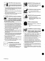 6
6
-
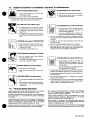 7
7
-
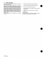 8
8
-
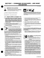 9
9
-
 10
10
-
 11
11
-
 12
12
-
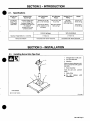 13
13
-
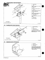 14
14
-
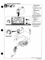 15
15
-
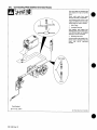 16
16
-
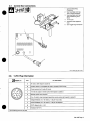 17
17
-
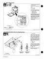 18
18
-
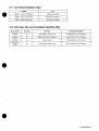 19
19
-
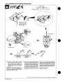 20
20
-
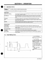 21
21
-
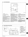 22
22
-
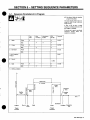 23
23
-
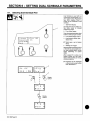 24
24
-
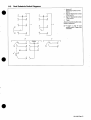 25
25
-
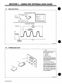 26
26
-
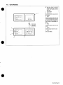 27
27
-
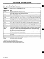 28
28
-
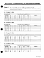 29
29
-
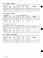 30
30
-
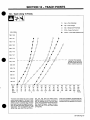 31
31
-
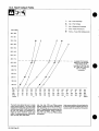 32
32
-
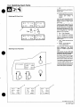 33
33
-
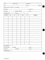 34
34
-
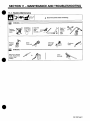 35
35
-
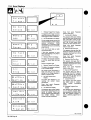 36
36
-
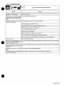 37
37
-
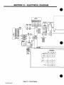 38
38
-
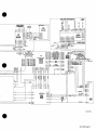 39
39
-
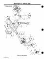 40
40
-
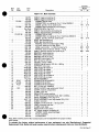 41
41
-
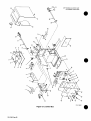 42
42
-
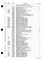 43
43
-
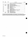 44
44
-
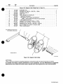 45
45
-
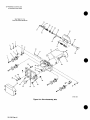 46
46
-
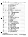 47
47
-
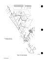 48
48
-
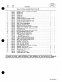 49
49
-
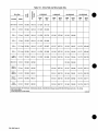 50
50
-
 51
51
-
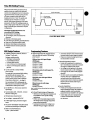 52
52
-
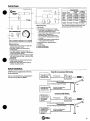 53
53
-
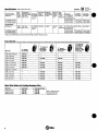 54
54
-
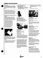 55
55
-
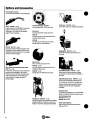 56
56
-
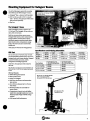 57
57
-
 58
58
-
 59
59
-
 60
60


Miller KJ164358 Le manuel du propriétaire
- Catégorie
- Système de soudage
- Taper
- Le manuel du propriétaire
- Ce manuel convient également à
dans d''autres langues
- English: Miller KJ164358 Owner's manual
Documents connexes
-
Miller SS-64M SWINGARC Le manuel du propriétaire
-
-
-
-
-
-
-
-
-