0523-54654
Instructions pour chanfreineuse sans l Bevel Boss®
CPBDK, CPBDBT, CPBDKE, CPBDADP, CPBMADP, CPBMADP29, CPBBADP
Les chanfreineuses sans l Bevel Boss® de REED sont conçues pour
être utilisées avec une meule à rectier les matrices sans l pour
chanfreiner le diamètre extérieur et/ou le diamètre intérieur d’un tuyau
en plastique. Les adaptateurs de chanfreineuse CPBDADP, CPBBADP,
et CPBMADP / CPBMADP29 sont conçus pour être utilisés avec les
meules à rectier les matrices DeWalt®/Milwaukee®/Bosch® sans l
UNIQUEMENT. Les instructions de montage sont fournies dans ce
document.
L’ensemble CPBDK de REED est complet avec une xation de
chanfrein avec protection extérieure, une fraise RBIT1, une meuleuse,
une pile DeWalt® et un chargeur dans un étui de rangement. L’outil de
base CPBDBT avec accessoire de chanfrein et meuleuse nécessite
une fraise et une pile DeWalt®. Reportez-vous à ces instructions pour
l’assemblage de la fraise dans le chanfrein. De nombreux utilisateurs
possèdent déjà la pile et peuvent l’utiliser sur cet outil REED.
REMARQUE : Le carénage intérieur CPBIDS no 94644 doit être
utilisé pour chanfreiner les diamètres intérieurs et est offert
comme accessoire.
SÉCURITÉ PERSONNELLE
1.
Restez vigilant, regardez ce que vous faites et utilisez votre bon
sens lors de l'utilisation d'un outil électrique. N'utilisez pas d'outil
lorsque vous êtes fatigué ou sous l'inuence de drogues, d'alcool
ou de médicaments. Un moment d'inattention lors de l'utilisation
d'outils électriques peut entraîner des blessures graves.
2.
Habillez-vous adéquatement. Ne portez pas de vêtements
trop grands ou de bijoux. Attachez vos cheveux s’ils sont longs.
Gardez vos cheveux, vos vêtements et vos gants loin des pièces
en mouvement. Les vêtements, les bijoux ou les cheveux longs
peuvent se prendre dans les pièces mobiles.
3.
Portez toujours des lunettes de sécurité.
INSTRUCTIONS DE FONCTIONNEMENT :
Cet outil doit être utilisé uniquement sur les tubes en plastique. Pour
régler la profondeur du chanfrein, desserrez le bouton de réglage et
faites glisser la plaque de guidage vers le haut ou vers le bas jusqu'à
ce que la quantité requise de la fraise à défoncer soit exposée au-
dessus de la plaque de guidage et serrez le bouton de réglage. Sur
le côté gauche du bouton de réglage, il y a quatre lignes gravées
sur l'adaptateur avec des incréments de 0,32 cm (1/8 po). Lorsque
vous utilisez la fraise RBIT1 avec la bague de réglage jusqu'en bas, la
chanfreineuse coupera un chanfrein de 1,59 cm (5/8 po) de long. En
alignant le bas de la bague de réglage avec la ligne gravée, la longueur
du chanfrein est réduite de 0,32 cm (1/8 po) pour chaque ligne.
Si la meule à rectier les matrices est en mesure d’atteindre
plusieurs vitesses, réglez-la sur le réglage le plus rapide. Mettez
la meule en marche et placez la plaque de guidage à plat contre
l'extrémité du tuyau. Amenez lentement la fraise contre le bord du
tuyau jusqu'à ce que le roulement à l'extrémité de la fraise soit en
contact avec le tuyau. Faites tourner lentement la chanfreineuse dans
le sens contraire des aiguilles d’une montre (antihoraire) pour
un chanfrein DE et dans le sens des aiguilles d’une montre
(horaire) pour un chanfrein DI, en veillant à maintenir le roulement
en contact avec le tuyau. Un deuxième passage rapide autour du
tuyau peut être nécessaire si le chanfrein n'est pas lisse. Un chanfrein
irrégulier peut se produire si la plaque de guidage n'est pas maintenue
perpendiculaire au tuyau et que le roulement sur la fraise n'est pas
maintenu contre le tuyau.
INSTRUCTIONS DE FONCTIONNEMENT POUR
FRAISE DE 2,54 CM (1 PO) UNIQUEMENT :
La fraise RBIT2 de 2,54 cm (1 po) enlève une grande quantité de
matériel. Par conséquent, il est FORTEMENT RECOMMANDÉ lors
de la coupe d'un chanfrein de 1,9 à 2,54 cm (¾ à 1 po) de profondeur
de faire deux passes autour du tuyau, en enlevant la moitié du
matériau à chaque passe. Pour le premier passage, réglez la bague
de réglage de sorte qu'elle s'aligne avec la ligne gravée à droite de
la vis de réglage et faites le premier passage autour du tuyau. Pour
terminer le chanfrein, réajustez la bague de réglage pour retirer le reste
du matériau.
SCHÉMA SYNOPTIQUE
LE BOUTON DE
RÉGLAGE DOIT
ÊTRE SITUÉ À 90 °
DE L’INTERRUPTEUR
COMME INDIQUÉ
PLAQUE DE
GUIDAGE
CARÉNAGE
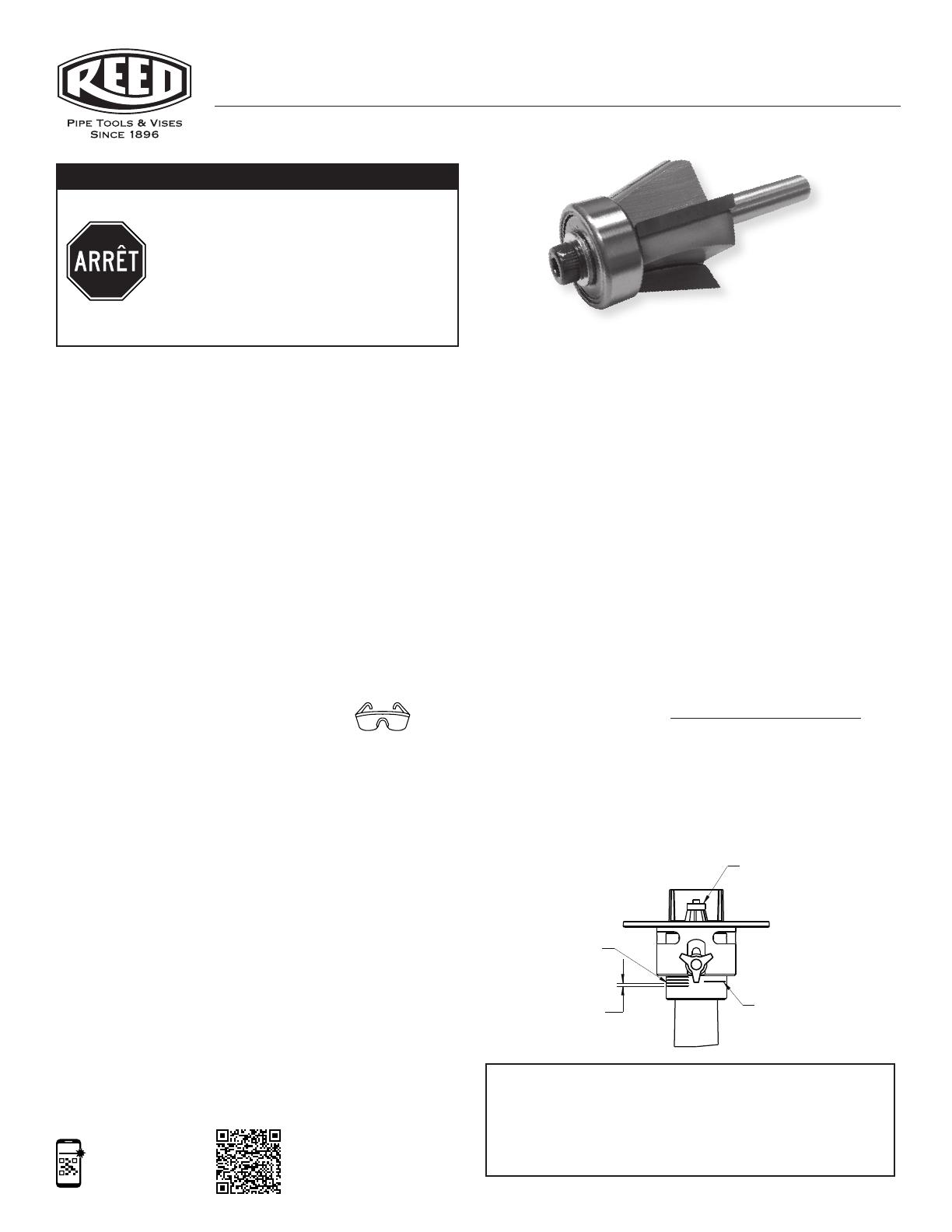
ASSEMBLY DIAGRAM 1
ASSEMBLY DIAGRAM 2
PINCE
ENVIRON
4,0 CM (5/32 PO)
LA PLAQUE DE
GUIDAGE DOIT ÊTRE
À NIVEAU AVEC LE
BAS DE LA FRAISE
VIS DE SERRAGE
ADAPTATEUR
MILWAUKEE®
CHANFREINEUSE
SCHÉMA SYNOPTIQUE
RECOMMANDÉ :
RÉGLER LA HAUTEUR DE
CETTE LIGNE POUR ENLEVER
LA MOITIÉ DU MATÉRIAU
POUR LA PREMIÈRE PASSE
SUR UN CHANFREIN PLUS
GRAND LORS DE L'UTILISA-
TION DE LA RBIT2
RBIT2
4 LIGNES DE
RÉFÉRENCE À INCRÉ-
MENTS DE 0,32 CM (1/8
PO) AFIN DE RÉGLER
LA DIMENSION DU
CHANFREIN
0,32 cm
(1/8 po)
LOCALISER LA MÈCHE
EN CARBURE POUR QUE
LA ZONE NON FINIE SUR
L'ARBRE SE TROUVE
JUSTE AU-DESSUS DU
HAUT DE LA PINCE
CPBDADP s’adapte au modèle DeWalt® DCG426B 20V MAX XR
CPBMADP convient aux modèles Milwaukee® 2784-20
and 2784-22 M18 FUEL™
CPBMADP29 convient aux modèles Milwaukee®
2984-20 and 2939-20 M18 FUEL™
S’adapte aux meules à rectier les matrices DeWalt
®
, Milwaukee
®
et Bosch
®
5
1. Vériez la longueur/le réglage du biseau de la
fraise à défoncer.
2. Démarrez la meule à rectier AVANT de toucher
le tuyau avec la fraise à défoncer. Elle doit être
à plein régime avant de toucher le tuyau.
3. Les nouveaux utilisateurs doivent faire un biseau
ou deux avant de travailler sur le tuyau du
chantier.
À LIRE AVANT D’UTILISER
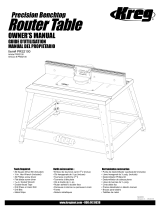
RBIT1
VIDEO DE
CAPACITACIÓN