
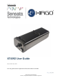
XT4392 User Guide
P a g e 1 | 10
CONFIDENTIAL AND PROPRIETARY
Disclosure, storage and use subject to non-disclosure agreement
XT4392 User Guide
Revised OCT 09, 2022
This user guide contains supplemental information about the XT4392.

XT4392 User Guide
P a g e 2 | 10
CONFIDENTIAL AND PROPRIETARY
Disclosure, storage and use subject to non-disclosure agreement
1. FUNCTIONAL DESCRIPTION ...................................................................................................................... 3
2. GENERAL OPERATION ............................................................................................................................... 4
2 INSTALLATION PROCEDURE ....................................................................................................................... 4
2.1 TERMINOLOGY .................................................................................................................................... 4
2.2 INSTALLATION ..................................................................................................................................... 4
3. ELECTRICAL CHARACTERISTICS ................................................................................................................. 6
3.1. MAXIMUM RATINGS .......................................................................................................................... 6
3.2. CHARGING CIRCUIT ............................................................................................................................ 6
4 REGULATORY STATEMENTS ....................................................................................................................... 8
4.1 FCC: ..................................................................................................................................................... 8
4.2 RADIOFREQUENCY RADIATION EXPOSURE INFORMATION: .............................................................. 8
4.3 INDUSTRY CANADA ............................................................................................................................. 8
GNSS Antenna Specifications ; Receive Only ........................................................................................ 9
2.45 GHz Antenna Specifications ........................................................................................................ 10
4G LTE Antenna Specifications ........................................................................................................... 10

XT4392 User Guide
P a g e 3 | 10
CONFIDENTIAL AND PROPRIETARY
Disclosure, storage and use subject to non-disclosure agreement
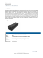
1. FUNCTIONAL DESCRIPTION
1.1. OVERVIEW
The XT4300 is used for asset tracking and tire monitoring services for fleets. The tire pressure monitoring
capabilities reduce tire-related costs, which subsequently reduces fleet costs from tire replacement and
expensive roadside service. The design engages the challenging industrial vehicle environment,
minimizing downtime and avoiding replacement expenses. The XT4300 features a powerful 32-bit
microprocessor and flexible power management algorithm, providing the capability of periodic reporting
of tire health, status, and location of remote assets. The device is designed to allow GPS tracking under
extreme conditions and leverages the latest tire pressure monitoring technology. The weatherproof case
(meets IEC 68-2-27 environmental standard and is IP67 certified) allows the XT4300 to be used for a
multitude of applications.
1.2. MECHANICAL
Mechanical
Dimensions
2.07" x 2.46" x 7.6" (52.7 x 62.6 x 193 mm)
Weight
TBD
Operating
Temperature
-22 to 158 degrees Fahrenheit (-30 to 70 degrees Celsius)
Charging
Temperature
32 to 140 degrees Farenheit (0 to 60 degrees Celsius)
Supported MNO
AT&T, Verizon

XT4392 User Guide
P a g e 4 | 10
CONFIDENTIAL AND PROPRIETARY
Disclosure, storage and use subject to non-disclosure agreement
2. GENERAL OPERATION
The XT4300 is connected to the vehicle and communicates to the server via the cellular network in one of
two operating modes: tracking and snapshot.
While in tracking mode, the device operates in a continuous integration mode where it is receiving GNSS
solutions at a rate of 1Hz. When in tracking mode the device default state is ACTIVE, and the device will
enter HIBERNATE as a secondary state for low power.
While in snapshot mode, the device enables the GNSS receiver to obtain a 2D positional fix and then turns
off the GNSS receiver. This mode will have the GNSS off, the cellular modem off, and the microprocessor
in a deep sleep or hibernate mode of operation.
When in snapshot mode the device default state is HIBERNATE and the device will enter ACTIVE to capture
the state of the system, environment, and report that data along with data recorded from sensors while
in HIBERNATE to the customer’s application server
2 INSTALLATION PROCEDURE
2.1 TERMINOLOGY
Term
Description
Unit
Xirgo XT6264
Asset
Customer product that the XT6264 is mounted to.
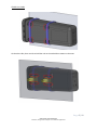
2.2 INSTALLATION
The Unit can be wire-tied to the Asset under the trailer chassis beam with its own Wiring Harness
Connected. The Label Side must look away from the metal while its being installed. The Zip tie must pass
through inside the holding features of the Unit.

XT4392 User Guide
P a g e 5 | 10
CONFIDENTIAL AND PROPRIETARY
Disclosure, storage and use subject to non-disclosure agreement
On the other side, there are ribs to hold the unit on the underside to mount on the asset.

XT4392 User Guide
P a g e 6 | 10
CONFIDENTIAL AND PROPRIETARY
Disclosure, storage and use subject to non-disclosure agreement
3. ELECTRICAL CHARACTERISTICS
3.1. MAXIMUM RATINGS
The maximum ratings are the limits to which the device can be subjected without permanently damaging
the device. Device reliability may be adversely affected by exposure to absolute-maximum ratings for
extended periods.
NOTE: The device is not guaranteed to operate properly at the maximum ratings.
Parameter
Parameter Name Min
Max
Unit
V_IN V_IN supply voltage 8.0 30.0 V
Current Consumption (Measured when supplied 12V)
min(mA)
max(mA)
Idle
31
52
Active Network
68
91
Active Network - GPS Off
58
81
Battery Charging - FAST MODE
365
380
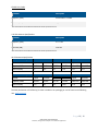
3.2. CHARGING CIRCUIT
At 12 V the device may draw up to 380 mA from power supply.
This device uses a Synchronous Step-Down Battery charger with switchable charge rates:
Fast charge
Fast charge is enabled when Main Voltage is above 9.0 V and the temperature is above 0 degrees Celsius
(32°F). If Main voltage drops below 9 V, it needs to raise back up to 9.25 V to begin fast charging. Expect
to see up to 140 mA from Main Voltage Power supply (At 12.0 V).
Slow charge
Slow charge is enabled when Main Voltage is below 9.0 V or the temperature is between 0 and -20 degrees
Celsius (32° to -4°F). The device will enter a No Charge state if the voltage goes below 4.4 V. Expect to see
up to 50 mA from Main Voltage Power supply (At 8.0 V).
NOTE: Slow charging may lead to an insufficient charge for long-term operation.

XT4392 User Guide
P a g e 7 | 10
CONFIDENTIAL AND PROPRIETARY
Disclosure, storage and use subject to non-disclosure agreement
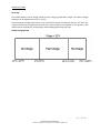
No Charge
The XT4300 battery cannot charge outside of their charging temperature ranges. The device charges
between 0 to 45 degrees Celsius (32° to 113°F).
Once the battery charge drops below 3.4 V, the device will enter low battery where it will retain any
unsent events but will not generate any new ones. Once the device is charged to 3.6 V or greater, it will
publish events retained prior to low battery state and begin generating new ones.
XT4300 Charging Graph

XT4392 User Guide
P a g e 8 | 10
CONFIDENTIAL AND PROPRIETARY
Disclosure, storage and use subject to non-disclosure agreement
4 REGULATORY STATEMENTS
4.1 FCC:
This device complies with Part 15 of the FCC Rules.
Operation is subject to the following two conditions:
(1) this device may not cause harmful interference, and
(2) this device must accept any interference received, including interference that may cause
Changes or modifications made to this equipment not expressly approved by Xirgo Technology may void
the FCC authorization to operate this equipment.
NOTE: This equipment has been tested and found to comply with the limits for a Class B digital device,
pursuant to Part 15 of the FCC Rules. These limits are designed to provide reasonable protection
against harmful interference in a residential installation. This equipment generates, uses and can
radiate radio frequency energy and, if not installed and used in accordance with the instructions,
may cause harmful interference to radio communications. However, there is no guarantee that
interference will not occur in a particular installation. If this equipment does cause harmful
interference to radio or television reception, which can be determined by turning the equipment
off and on, the user is encouraged to try to correct the interference by one or more of the following
measures:
• Reorient or relocate the receiving antenna.
• Increase the separation between the equipment and receiver.
• Connect the equipment into an outlet on a circuit different from that to which the receiver is
connected.
• Consult the dealer or an experienced radio/TV technician for help.
4.2 RADIOFREQUENCY RADIATION EXPOSURE INFORMATION:
This equipment complies with FCC radiation exposure limits set forth for an uncontrolled environment.
This equipment should be installed and operated with minimum distance of 20 cm between the radiator
and your body. This transmitter must not be co-located or operating in conjunction with any other antenna
or transmitter.
4.3 INDUSTRY CANADA
This device complies with Industry Canada license-exempt RSS standard(s). Operation is subject to the
following two conditions:
(1) this device may not cause interference, and
(2) this device must accept any interference, including interference that may cause undesired
operation of the device.

XT4392 User Guide
P a g e 9 | 10
CONFIDENTIAL AND PROPRIETARY
Disclosure, storage and use subject to non-disclosure agreement
Le présent appareil est conforme aux CNR d'Industrie Canada applicables aux appareils radio exempts
de licence. L'exploitation est autorisée aux deux conditions suivantes :
(1) l'appareil ne doit pas produire de brouillage, et
(2) l'utilisateur de l'appareil doit accepter tout brouillage radioélectrique subi, même si le
brouillage est susceptible d'en compromettre le onctionnement.
Under Industry Canada regulations, this radio transmitter may only operate using an antenna of a type
and maximum (or lesser) gain approved for the transmitter by Industry Canada. To reduce potential radio
interference to other users, the antenna type and its gain should be so chosen that the equivalent
isotropically radiated power (e.i.r.p.) is not more than that necessary for successful communication.
Conformément à la réglementation d'Industrie Canada, le présent émetteur radio peut fonctionner avec
une antenne d'un type et d'un gain maximal (ou inférieur) approuvé pour l'émetteur par Industrie Canada.
Dans le but de réduire les risques de brouillage radioélectrique à l'intention des autres utilisateurs, il faut
choisir le type d'antenne et son gain de sorte que la puissance isotrope rayonnée équivalente (p.i.r.e.) ne
dépasse pas l'intensité nécessaire à l'établissement d'une communication satisfaisante.
This radio transmitter (IC:10281A-XT4392, Model Number: XT4392) has been approved by Industry
Canada to operate with the antenna types listed below with the maximum permissible gain and
required antenna impedance for each antenna type indicated. Antenna types not included in this list,
having a gain greater than the maximum gain indicated for that type, are strictly prohibited for use
with this device.
Cet émetteur radio (identifier le périphérique par numéro de certification, ou le numéro de modèle si
Catégorie II) a été approuvé par Industrie Canada pour fonctionner avec les types d'antennes énumérées
ci-dessous avec le gain maximal admissible et l'impédance d'antenne requise pour chaque antenne type
indiqué. Types d'antennes ne figurent pas dans cette liste, ayant un gain supérieur au maximum gagner
indiqué pour ce type, sont strictement interdites pour une utilisation avec cet appareil.
GNSS Antenna Specifications ; Receive Only
Parameter
Description
Band Support
GPS, SBAS: 1575.42 MHz ± 1.02 MHz
GLONASS: 1575.42MHz, 1602MHz
GPS: ≤ 2.5 dBi
GLONASS: ≤ 3.0 dBi
Peak Realized Gain
UHF Antenna Specifications

XT4392 User Guide
P a g e 10 | 10
CONFIDENTIAL AND PROPRIETARY
Disclosure, storage and use subject to non-disclosure agreement
Parameter
Description
Frequency (GHz)
433.92 MhZ ± 0.5 MHz
Peak Gain (dBi)
≤(-)5 dBi
1Gain measured with all the Mechanical Elements with 3D printed Enclosures
2.45 GHz Antenna Specifications
Parameter
Description
Frequency (GHz)
2.4 - 2.48
Peak Gain (dBi)
≤2.6 dBi
1Gain measured with all the Mechanical Elements with 3D printed Enclosures
4G LTE Antenna Specifications
Specification Description
Band 12
Band 13
Band 4
Channel
Uplink
Downlink
Uplink
Downlink
Uplink
Downlink
Frequency (MHz)
699-716
729-746
777-787
746-756
1710-1755
2110-2155
Peak Gain [dBi]
<1
<1.9
<1.1
<1.9
<5.6
<3.2
Specification Description
Band 20
Band 28
Band 2
Channel
Uplink
Downlink
Uplink
Downlink
Uplink
Downlink
Frequency (MHz)
832-862
791-821
703-748
758-803
1850-1910
1930-1990
Peak Gain [dBi]
<0.2
<0.2
<1.9
<0.35
<5.0
<3.8
The DOC (Declaration of Conformity) is either included in the packaging or can be found at the following
link: www.xirgo.com
-
 1
1
-
 2
2
-
 3
3
-
 4
4
-
 5
5
-
 6
6
-
 7
7
-
 8
8
-
 9
9
-
 10
10


dans d''autres langues
- English: XIRGO XT4392 User guide
Autres documents
-
LG TLVLM3IU-N Manuel utilisateur
-
Samsara Unpowered Asset Gateway AG51 Manuel utilisateur
-
Fortinet FG-81F Unified Threat Protection Mode d'emploi
-
Telit Wireless Solutions LN940 WWAN M.2 Manuel utilisateur
-
Mediatek MT7922A12L Mode d'emploi
-
Samsara AG46 Manuel utilisateur
-
-
-
-
Rand McNally OverDryve 8 Pro Guide de démarrage rapide