Skil OS5937-00 Le manuel du propriétaire
- Catégorie
- Outils électroportatifs
- Taper
- Le manuel du propriétaire

WARNING: To reduce the risk of injury, the user must read and understand the
Owner’s Manual before using this product. Save these instructions for future reference.
AVERTISSEMENT : Afin de réduire les risques de blessure, l’utilisateur doit lire et
comprendre le guide d’utilisation avant d’utiliser cet article. Conservez le présent guide
afin de pouvoir le consulter ultérieurement.
ADVERTENCIA : Para reducir el riesgo de lesiones, el usuario debe leer y comprender
el Manual del operador antes de utilizar este producto. Guarde estas instrucciones para
consultarlas en caso sea necesario.
Owner’s Manual
Guide d’utilisation
Manual del propietario
For Customer Service
Pour le service à la clientèle
Servicio al cliente
20V Brushless Multi-Tool
Outil sans balai à multiples fonctions de 20 V
Multiherramienta sin escobillas de 20 V
1-877-SKIL-999 OR www.skil.com
Model/ Modelo/ Modèle: OS5937-00

2
TABLE OF CONTENTS
General Power Tool Safety Warnings .............................3-5
Safety Warnings for Multi-Tool .....................................5
Symbols .....................................................6-9
Get to Know Your Multi-Tool ......................................10
Specications .................................................10
Operating Instructions .......................................11-19
Selecting the Accessory for Your Application .......................20
Maintenance ...................................................21
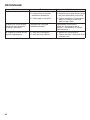
Troubleshooting ...............................................21
Limited Warranty Of SKIL Consumer Tools .........................22
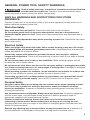
WARNING
• Some dust created by power sanding, sawing, grinding, drilling and other construction
activities contains chemicals known to the State of California to cause cancer, birth defects
or other reproductive harm. Some examples of these chemicals are:
– Lead from lead-based paints.
– Crystalline silica from bricks, cement, and other masonry products.
– Arsenic and chromium from chemically-treated lumber.
– Your risk from these exposures varies, depending upon how often you do this type of work.
• To reduce your exposure to these chemicals:
– Work in a well-ventilated area.
– Work with approved safety equipment, such as dust masks that are specially designed to
lter out microscopic particles.
– Avoid prolonged contact with dust from power sanding, sawing, grinding, drilling, and
other construction activities. Wear protective clothing and wash exposed areas with soap
and water. Allowing dust to get into your mouth or eyes or to lie on the skin may promote
absorption of harmful chemicals.

3
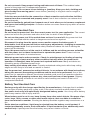
GENERAL POWER TOOL SAFETY WARNINGS
WARNING Read all safety warnings, instructions, illustrations and specications
provided with this power tool. Failure to follow all instructions listed
below may result in electric shock, re and/or serious injury.
SAVE ALL WARNINGS AND INSTRUCTIONS FOR FUTURE
REFERENCE.
The term “power tool” in the warnings refers to your mains-operated (corded) power tool or
battery-operated (cordless) power tool.
Work Area Safety
Keep work area clean and well lit. Cluttered or dark areas invite accidents.
Do not operate power tools in explosive atmospheres, such as in the presence of
ammable liquids, gases or dust. Power tools create sparks which may ignite the dust or
fumes.
Keep children and bystanders away while operating a power tool. Distractions can cause
you to lose control.
Electrical Safety
Power tool plugs must match the outlet. Never modify the plug in any way. Do not use
any adapter plugs with earthed (grounded) power tools. Unmodied plugs and matching
outlets will reduce risk of electric shock.
Avoid body contact with earthed or grounded surfaces, such as pipes, radiators,
ranges and refrigerators. There is an increased risk of electric shock if your body is earthed
or grounded.
Do not expose power tools to rain or wet conditions. Water entering a power tool will
increase the risk of electric shock.
Do not abuse the cord. Never use the cord for carrying, pulling or unplugging the power
tool. Keep cord away from heat, oil, sharp edges or moving parts. Damaged or entangled
cords increase the risk of electric shock.
When operating a power tool outdoors, use an extension cord suitable for outdoor use.
Use of a cord suitable for outdoor use reduces the risk of electric shock.
If operating a power tool in a damp location is unavoidable, use a ground fault circuit
interrupter (GFCI) protected supply. Use of a GFCI reduces the risk of electric shock.
Personal Safety
Stay alert, watch what you are doing and use common sense when operating a power
tool. Do not use a power tool while you are tired or under the inuence of drugs,
alcohol or medication. A moment of inattention while operating power tools may result in
serious personal injury.
Use personal protective equipment. Always wear eye protection. Protective equipment
such as a dust mask, non-skid safety shoes, hard hat or hearing protection used for
appropriate conditions will reduce personal injuries.
Prevent unintentional starting. Ensure the switch is in the off-position before
connecting to power source and/or battery pack, picking up or carrying the tool.
Carrying power tools with your nger on the switch or energising power tools that have the
switch on invites accidents.
Remove any adjusting key or wrench before turning the power tool on. A wrench or a
key left attached to a rotating part of the power tool may result in personal injury.

4
Do not overreach. Keep proper footing and balance at all times. This enables better
control of the power tool in unexpected situations.
Dress properly. Do not wear loose clothing or jewellery. Keep your hair, clothing and
gloves away from moving parts. Loose clothes, jewellery or long hair can be caught in
moving parts.
If devices are provided for the connection of dust extraction and collection facilities,
ensure these are connected and properly used. Use of dust collection can reduce dust-
related hazards.
Do not let familiarity gained from frequent use of tools allow you to become complacent
and ignore tool safety principles. A careless action can cause severe injury within a fraction
of a second.
Power Tool Use And Care
Do not force the power tool. Use the correct power tool for your application. The correct
power tool will do the job better and safer at the rate for which it was designed.
Do not use the power tool if the switch does not turn it on and off. Any power tool that
cannot be controlled with the switch is dangerous and must be repaired.
Disconnect the plug from the power source and/or remove the battery pack, if
detachable, from the power tool before making any adjustments, changing accessories,
or storing power tools. Such preventive safety measures reduce the risk of starting the
power tool accidentally.
Store idle power tools out of the reach of children and do not allow persons unfamiliar
with the power tool or these instructions to operate the power tool. Power tools are
dangerous in the hands of untrained users.
Maintain power tools and accessories. Check for misalignment or binding of moving
parts, breakage of parts and any other condition that may affect the power tool’s
operation. If damaged, have the power tool repaired before use. Many accidents are
caused by poorly maintained power tools.
Keep cutting tools sharp and clean. Properly maintained cutting tools with sharp cutting
edges are less likely to bind and are easier to control.
Use the power tool, accessories and tool bits etc. in accordance with these instructions,
taking into account the working conditions and the work to be performed. Use of the
power tool for operations different from those intended could result in a hazardous situation.
Keep handles and grasping surfaces dry, clean and free from oil and grease. Slippery
handles and grasping surfaces do not allow for safe handling and control of the tool in
unexpected situations.
Battery Tool Use And Care
Recharge only with the charger specied by the manufacturer. A charger that is suitable
for one type of battery pack may create a risk of re when used with another battery pack.
Use power tools only with specically designated battery packs. Use of any other battery
packs may create a risk of injury and re.
When battery pack is not in use, keep it away from other metal objects, like paper clips,
coins, keys, nails, screws or other small metal objects, that can make a connection
from one terminal to another. Shorting the battery terminals together may cause burns or a
re.
Under abusive conditions, liquid may be ejected from the battery; avoid contact. If
contact accidentally occurs, ush with water. If liquid contacts eyes, additionally seek
medical help. Liquid ejected from the battery may cause irritation or burns.

5
Do not use a battery pack or tool that is damaged or modied. Damaged or modied
batteries may exhibit unpredictable behaviour resulting in re, explosion or risk of injury.
Do not expose a battery pack or tool to re or excessive temperature. Exposure to re or
temperature above 265 °F may cause explosion.
Follow all charging instructions and do not charge the battery pack or tool outside the
temperature range specied in the instructions. Charging improperly or at temperatures
outside the specied range may damage the battery and increase the risk of re.
Service
Have your power tool serviced by a qualied repair person using only identical
replacement parts. This will ensure that the safety of the power tool is maintained.
Never service damaged battery packs. Service of battery packs should only be performed
by the manufacturer or authorized service providers.
SAFETY WARNINGS FOR MULTI-TOOL
Hold the power tool by insulated gripping surfaces, when performing an operation
where the cutting tool may contact hidden wiring or its own cord. Cutting tool contacting
a “live” wire may make exposed metal parts of the tool “live” and could give the operator an
electric shock.
A suitable breathing respirator must be worn while sanding lead paint, some woods
and metal to avoid breathing the harmful/toxic dust or air.
Always wear safety goggles and a dust mask when sanding, especially when sanding
over-head.
The machine is not suitable for wet sanding.
Do not use sanding paper larger than needed. Extra paper extending beyond the sanding
pad can cause serious lacerations.
Secure the workpiece. A workpiece clamped with clamping devices or in a vice is held more
securely than by hand.
Keep hands away from the cutting range. Do not reach under the workpiece. Contact with
the blade can lead to injuries.
Keep your hands away from the motor-housing vents. Hot air comes from the vents during
operation.

6
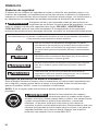
SYMBOLS
Safety Symbols
The purpose of safety symbols is to attract your attention to possible dangers. The safety
symbols and the explanations with them deserve your careful attention and understanding.
The symbol warnings do not, by themselves, eliminate any danger. The instructions and
warnings they give are no substitutes for proper a cident prevention measures.
WARNING Be sure to read and understand all safety instructions in this Owner’s
Manual, including all safety alert symbols such as “DANGER,”
“WARNING,” and “CAUTION” before using this tool. Failure to following all instructions listed
below may result in electric shock, re, and/or serious personal injury.
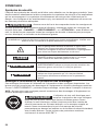
The denitions below describe the level of severity for each signal word. Please read the manual
and pay attention to these symbols.
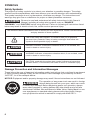
This is the safety alert symbol. It is used to alert you to potential
personal injury hazards. Obey all safety messages that follow this
symbol to avoid possible injury or death.
DANGER DANGER indicates a hazardous situation which, if not avoided, will
result in death or serious injury.
WARNING WARNING indicates a hazardous situation which, if not avoided, could
result in death or serious injury.
CAUTION CAUTION, used with the safety alert symbol, indicates a hazardous
situation which, if not avoided, will result in minor or moderate injury.
Damage Prevention and Information Messages
These inform the user of important information and/or instructions that could lead to equipment
or other property damage if they are not followed. Each message is preceded by the word
“NOTICE”, as in the example below:
NOTICE: Equipment and/or property damage may result if these instructions are not followed.
WARNING The operation of any power tools can result in foreign
objects being thrown into your eyes, which can result
in severe eye damage. Before beginning power tool operation, always
wear safety goggles or safety glasses with side shields and a full face
shield when needed. We recommend a Wide Vision Safety Mask for use
over eyeglasses or standard safety glasses with side shields. Always
use eye protection which is marked to comply with ANSI Z87.1..

7
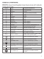
SYMBOLS (CONTINUED)
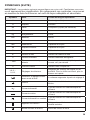
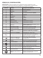
IMPORTANT: Some of the following symbols may be used on your tool. Please study them
and learn their meaning. Proper interpretation of these symbols will allow you to operate the
tool better and more safely.
Symbol Name Designation/Explanation
V Volts Voltage (potential)
AAmperes Current
Hz Hertz Frequency (cycles per second)
WWatt Power
kg Kilograms Weight
min Minutes Time
s Seconds Time
Wh Watt-hours Battery capacity
Ah Ampere-Hours Battery capacity
ØDiameter Size of drill bits, grinding wheels, etc.
n0No load speed Rotational speed, at no load
nRated speed Maximum attainable speed
…/min Revolutions or reciprocation
per minute Revolutions, strokes, surface speed,
orbits, etc. per minute
0Off position Zero speed, zero torque...
1,2,3,…
I,II,III, Selector settings Speed, torque or position settings. Higher
number means greater speed
Innitely variable selector
with off Speed is increasing from 0 setting
Arrow Action in the direction of arrow
Alternating current Type or a characteristic of current
Direct current Type or a characteristic of current
Alternating or direct current Type or a characteristic of current
Class II tool Designates Double Insulated Construction
tools.
Earthing terminal Grounding terminal
Li-ion RBRC seal Designates Li-ion battery recycling
program

8
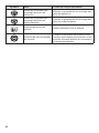
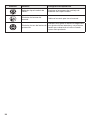
Symbol Name Designation/Explanation
Ni-Cad RBRC seal Designates Ni-Cad battery recycling
program
Read manual symbol Alerts user to read manual
Wear eye protection symbol Always wear safety goggles or safety
glasses with side shields and a full face
shield when operating this product.

9
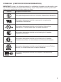
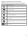
SYMBOLS (CERTIFICATION INFORMATION)
IMPORTANT: Some of the following symbols for certication information may be used on your
tool. Please study them and learn their meaning. Proper interpretation of these symbols will
allow you to operate the tool better and more safely.
Symbol Designation/Explanation
This symbol designates that this tool is listed by Underwriters Laboratories.
This symbol designates that this component is recognized by
Underwriters Laboratories.
This symbol designates that this tool is listed by Underwriters
Laboratories, to United States and Canadian Standards.
This symbol designates that this tool is listed by the Canadian
Standards Association.
This symbol designates that this tool is listed by the Canadian
Standards Association, to United States and Canadian Standards.
This symbol designates that this tool is listed by the Intertek Testing
Services, to United States and Canadian Standards.
This symbol designates that this tool complies to NOM Mexican
Standards.

10
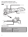
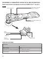
GET TO KNOW YOUR MULTI-TOOL
20V PWRCORE™ Brushless Multi-Tool
Locking Rod
On/Off SwitchClamping Lever
Variable-Speed Dial
Ribs
Drive Shaft
Fig. 1
LED Light
SPECIFICATIONS
General
Max Oscillation Rate 11000~17000 /min
Oscillation Angle ±1.8°
Recommended working temperature 14 ~ 104°F (-10 ~ 40℃)
Recommended storage temperature 32 ~ 104°F (0 ~ 40°C)

11
OPERATING INSTRUCTIONS
WARNING To reduce the risk of re, personal injury, and product damage due to
a short circuit, never immerse your tool, battery pack or charger in
uid or allow a uid to ow inside them. Corrosive or conductive uids, such as seawater,
certain industrial chemicals, and bleach or bleach-containing products, etc, can cause a short
circuit.
WARNING If any parts are damaged or missing do not operate this product until
the parts are replaced. Use of this product with damaged or missing
parts could result in serious personal injury.
WARNING Do not attempt to modify this multi-tool or create accessories not
recommended for use with this multi-tool. Any such alteration or
modication is misuse and could result in a hazardous condition leading to possible serious
injury.
WARNING To prevent accidental starting that could cause serious personal injury,
always remove the battery pack from the multi-tool when assembling
parts.
This cordless multi-tool must be used only with the battery packs and chargers listed below:
Battery Pack Charger
2Ah 2.5Ah 4Ah 5Ah
SKIL BY519701
SKIL BY519702 SKIL BY519703 SKIL BY519601 SKIL BY519603 SKIL SC535801
SKIL QC536001
NOTICE: Please refer to the charger and battery manual for detailed operating information.
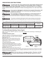
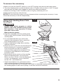
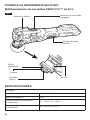
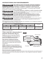
To Attach/Detach Battery Pack (Fig.2)
Make sure that the ON/OFF switch is in the “OFF” position when attaching or detaching the
battery pack.
To attach the battery pack:
Align the raised rib on the battery pack with the
grooves of the tool, and then slide the battery
pack onto the tool.
NOTICE: Make sure that the latch on the
battery pack snaps into place and that the
battery pack is secured to the tool before
beginning operation.
To detach the battery pack:
Depress the battery-release button located
on the front of the battery pack to release the
battery pack. Pull the battery pack out and
remove it from the tool.
NOTICE: When placing the battery pack on
the tool, be sure that the raised rib on battery pack aligns with the groove inside the tool and
that the latches snap into place properly. Improper attachment of the battery pack can cause
damage to internal components.
WARNING Battery tools are always in operating condition. Therefore, the ON/
OFF switch should always be in OFF position when not in use or
carrying at your side.
Fig. 2
Detach
Attach Battery-release
Button

12
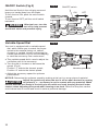
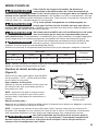
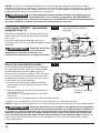
ON/OFF Switch (Fig.3)
Hold the tool rmly in the soft grip area and
keep your hands away from the blade.
To turn the tool ON, push the on/off switch
forward.
To turn the tool OFF, pull the on/off switch
backward.
WARNING After tool use, turn the
tool off to help prevent
accidental starts and possible injury.
Variable-Speed Dial
Your tool is equipped with a variable-speed
dial, which allows you to match the proper
speed to the material being cut, sawed,
scraped, or sanded, thereby enhancing the
overall performance of your tool and helping
to save the accessory from undue wear.
a. The variable-speed dial is used to adjust the
oscillation rate of the accessory.
b. Turn the dial to increase or decrease the
speed. (Fig.4)
Position “1” selects the slowest speed;
Position “6” selects the fastest speed.
c. Adjust the accessory speed for optimum
performance.
NOTICE: Determine the optimum speed by making a trial cut in a scrap piece of material.
CAUTION Adjust the speed only when the tool is off or when the tool is running
at no-load (i. e ., accessory is not in contact with any material). Make
sure to hold the tool rmly in the soft grip area with one hand, keeping the tool under
control, when adjusting the speed when running at no-load. Failure to obey this caution
could cause loss of control and result in serious personal damage.
Fig. 3 ON/OFF switch
ON OFF
Fig. 4
Variable-speed dial

13
LED Light
Your tool is equipped with two LED lights,
located on the head of the tool. This provides
additional light on the surface of the work piece
for operation in lower-light areas.
The LED light will automatically turn on when
the on/off switch is in “ON” position, and off
when the on/off switch is in “OFF” position.
(Fig.5)
When the tool and/or battery pack becomes
overloaded or too hot, the internal sensors will
turn the tool off, and the LED lights will ash
rapidly to indicate the over-load or
over-temperature condition.
Rest the tool for a while or place the tool and battery pack separately under air ow to cool.
Installing and Removing Accessories
WARNING Always turn the tool off and remove the battery pack before assembling
parts.
WARNING Wear protective gloves when changing accessories. Accessories
become hot after prolonged use. And the sharp edges of the accessories
can cause personal injury.
WARNING Check that the accessories are correctly attached. Incorrect or
insecurely attached accessories can come loose during operation
and cause a hazard.
Fig.5
LED Lights

14
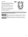
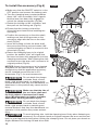
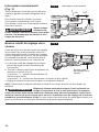
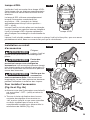
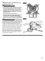
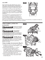
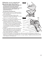
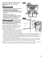
To install the accessory (Fig.6)
a. Make sure that the ON/OFF switch is in the
OFF position and remove the battery pack.
b. Turn the clamping lever counterclockwise
about 140° until an audible “click” signals
that the lever has been fully engaged to
unlock the clamp mechanism (Fig.6a).
c. Rotate the locking rod 90° clockwise, and
then pull out the locking rod (Fig.6b).
d. Ensure that the locking rod and the
drive shaft are clean before installing the
accessory.
e. Position the accessory on the drive shaft,
making sure that all the grooves on the
accessory align with the ribs on the drive
shaft (Fig.6c).
f. Insert the locking rod into the drive shaft,
then press the locking rod and rotate it 90°
counterclockwise so that it is secured in the
drive shaft (Fig.6c).
g. Return the clamping lever to its original
positon. An audible “click” will signal that
the lever has been fully engaged to lock the
clamping mechanism. After hearing the click,
continue to turn the lever until it returns to its
original position (Fig.6c).
NOTICE: Attach the accessory in the desired
orientation for the task at hand. The shaft is
congured so that the application accessory
can be installed around the tool in 30°
increments (Fig.7) for most accessories.
WARNING Do not attach the plunge-
cut blade, ush circular
blade, rigid scraper blade, or carbide grout-
removal blade so that they face backwards, as
attachment in this position may cause serious
injury.,
WARNING Make sure that the ribs of
the tool drive shaft and
the lock pattern of accessories t each
other. Misalignment can lead to unstable
attachment, causing personal injury.
WARNING Do not attach the plunge-
cut blade, ush circular
blade, rigid scraper blade or carbide grout-
removal blade so that they face backwards, as
operation in this position may cause serious
injury.
CAUTION To avoid pinching skin, hold the clamping lever rmly when fastening an
accessory. Do not place hands or ngers between the lever and the tool
body to guard against bruising when locking the clamping lever. Do not place your hands or
ngers between the locking rod and drive shaft.
-90o
-60o
-30o
90o
60o
30o
0o
Fig.7
140o
Fig.6a
90o
Fig.6b
Fig.6c

15
To remove the accessory
a. Make sure that the ON/OFF switch is in the OFF position and remove the battery pack.
b. Turn the clamping lever counterclockwise (refer to Fig.6a) until you hear a “click” to signal
that the lever has been fully engaged to unlock the clamp mechanism.
c. Rotate the locking rod 90° clockwise (refer to Fig.6b), and then pull it off.
d. Remove the accessory from the tool.
NOTICE: Do not allow the locking rod face downward when removing the accessory. It may
cause the accessory to fall off unexpectedly.
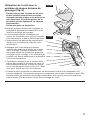
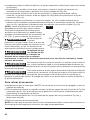
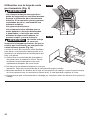
Using with Sanding Base Plate
Set (Fig.8)
WARNING
– Always wear safety goggles or safety
glasses with side shields during power
tool operation. If the operation is dusty,
also wear a dust mask.
– Wear protective gloves.
a. Align the sandpaper with the sanding plate
and use your hand to press it rmly onto the
sanding plate.
b. It is recommended that you sand a test
sample of the workpiece rst to select the
best sanding paper for your job.
c. Select a high-speed range when sanding
with the multi-tool.
d. Allow the tool to reach its full selected speed
before allowing it to contact the workpiece.
Press the power tool with the sanding
plate set rmly against the workpiece. This
provides for good adhesion and prevents
premature wear.
e. Work with the entire surface of the sanding
plate and sanding paper, not just the tip.
When one tip or corner of the sanding paper
is worn, the sandpaper can be removed,
turned 120°, and reattached.
f. Sand the workpiece in a continuous motion
with moderate pressure. Excessive pressure
does not increase the rate of removal. It will result in unwanted sanding marks and cause
the sanding paper to wear more quickly. It can also cause tool overload.
Fig.8a
Fig.8b

16
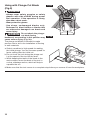
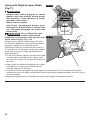
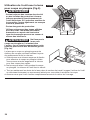
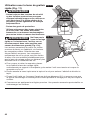
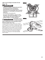
Using with Plunge-Cut Blade
(Fig.9)
WARNING
– Always wear safety goggles or safety
glasses with side shields during power
tool operation. If the operation is dusty,
also wear a dust mask.
– Wear protective gloves.
– Use sharp, undamaged blades only.
Deformed or blunt blades or blades that
are otherwise damaged can break and
cause injury.
WARNING Do not attach the plunge-
cut blade facing
backward, as operation in this position may
cause serious injury (Fig. 9a).
The plunge-cut blade is intended to make
precise cuts to aid in the installation of ooring
or wall materials.
a. Select a medium to high speed for making
the initial plunge. You can increase speed for
faster cutting after the initial cut.
b. Do not force the tool during the plunge cut.
Let the speed of the tool do the work.
c. While keeping the teeth of the blade in the
work surface, move the back of the tool in
a slow, sideways motion, which will help to
expedite the cut.
d. Make sure that the tool comes to a complete stop before you remove it from the workpiece.
Fig. 9b
X
Fig.9a

17
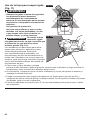
Using with Flush Circular Blade
(Fig.10)
WARNING
– Always wear safety goggles or safety
glasses with side shields during power
tool operation. If the operation is dusty,
also wear a dust mask.
– Wear protective gloves.
– Use sharp, undamaged blades only.
Deformed or blunt blades or blades that
are otherwise damaged can break.
WARNING Do not attach the ush
circular blade facing
backward, as operation in this position may
cause serious injury (Fig. 10a).
The ush circular blade is ideal for making
cuts in wood, plaster, drywall, non-ferrous
metals, thin sheet metal, and other materials.
The blade works best on softer woods, such
as pine. For harder woods, the blade life
will be limited. Allow the tool to reach its full
selected speed before allowing it to contact the
workpiece.
Fig. 10b
X
Fig.10a

18
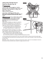
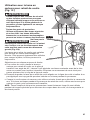
Using with Rigid Scraper Blade
(Fig.11)
WARNING
– Always wear safety goggles or safety
glasses with side shields during power
tool operation. If the operation is dusty,
also wear a dust mask.
– Wear protective gloves.
– Use sharp, undamaged blades only.
Deformed or blunt blades or blades that
are otherwise damaged can break and
cause injury.
WARNING Do not attach the rigid
scraper blade facing
backward, as operation in this position may
cause serious injury (Fig. 11a).
Scrapers are suitable for removing old coats
of varnish or adhesives and removing bonded
carpeting. Select low to medium speed.
Carpet/vinyl ooring is removed more easily if
it is scored prior to removal, so that the scraper
blade can move more freely underneath the
ooring material.
a. To cut and remove carpet, rst place the rigid
scraper blade vertically on the carpet, then
turn the tool on and cut through the carpet to
the oor.
b. Next, place the blade at between the carpet
and the oor to remove the adhesive and
free the carpet from the oor.
c. Put the tool on the workpiece at a at angle (not more than 20°) and make sure that the
locking rod does not make contact with surface during the scraping process, so as to not cut
into the surface.
d. Begin with light pressure. Excessive pressure can gouge or damage surfaces.
Fig. 11b
X
Fig.11 a

19
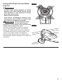
Using with Carbide Grout-
Removal Blade (Fig.12)
WARNING
-Always wear safety goggles or safety
glasses with side shields during power tool
operation. If the operation is dusty, also
wear a dust mask.
-Wear protective gloves.
-Use sharp, undamaged blades only.
Deformed or blunt blades or blades that are
otherwise damaged can break and cause
injury.
WARNING Do not attach the carbide
grout-removal blade
facing backward, as operation in this
position may cause serious injury
(Fig. 12a).
Grout-removal blades are ideal for removing
damaged or cracked grout. They can also
be used to cut plaster, porous concrete, and
masonry. Select a medium to high speed.
a. To remove grout, place the carbide grout-
removal blade against the workpiece at a
90° angle. Allow the tool to reach its full
selected speed before allowing it to contact
the workpiece. Use a back-and-forth motion to
make several passes along the grout line.
b. Try to keep the grout-removal blade aligned
with the grout line and be careful not to apply
too much side pressure on the grout blade during the process.
c. Cut out the grout around the tile, then use a hand chisel to remove the tile from the wall.
If the blade jams during the grout removal process, you can use a brush to clean the grit and
resume work.
NOTICE: When cutting grout, masonry and porous cement, take into consideration that the
accessories wear heavily when used for longer periods of time.
Fig. 12b
X
Fig.12 a

20
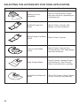
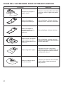
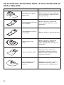
SELECTING THE ACCESSORY FOR YOUR APPLICATION
Accessory Materials
Sanding Pad and
Sandpaper
Bare or Painted Wood, Plaster,
and other surfaces, depending on
sandpaper grit
Bi-Metal Plunge-Cut
Blade Wood, Plastic, Drywall, Soft
Metals, and other materials
Wood Plunge-Cut Blade
(HCS) Wood, Plastic, Drywall
Flush Circular Blade
(HCS)
Wood, Plastic, Drywall, Non-
Ferrous Metals, Thin Sheet Metal,
and other materials
Rigid Scraper Blade Paint & Varnish, Bonded Carpet,
Soft Adhesives, Vinyl Flooring,
Wood, and other oor coverings
Carbide Grout-Removal
Blade Tile or Tile Crevice, Grout, Plaster,
Porous Concrete, and Masonry
La page est en cours de chargement...
La page est en cours de chargement...
La page est en cours de chargement...
La page est en cours de chargement...
La page est en cours de chargement...
La page est en cours de chargement...
La page est en cours de chargement...
La page est en cours de chargement...
La page est en cours de chargement...
La page est en cours de chargement...
La page est en cours de chargement...
La page est en cours de chargement...
La page est en cours de chargement...
La page est en cours de chargement...
La page est en cours de chargement...
La page est en cours de chargement...
La page est en cours de chargement...
La page est en cours de chargement...
La page est en cours de chargement...
La page est en cours de chargement...
La page est en cours de chargement...
La page est en cours de chargement...
La page est en cours de chargement...
La page est en cours de chargement...
La page est en cours de chargement...
La page est en cours de chargement...
La page est en cours de chargement...
La page est en cours de chargement...
La page est en cours de chargement...
La page est en cours de chargement...
La page est en cours de chargement...
La page est en cours de chargement...
La page est en cours de chargement...
La page est en cours de chargement...
La page est en cours de chargement...
La page est en cours de chargement...
La page est en cours de chargement...
La page est en cours de chargement...
La page est en cours de chargement...
La page est en cours de chargement...
La page est en cours de chargement...
La page est en cours de chargement...
La page est en cours de chargement...
La page est en cours de chargement...
La page est en cours de chargement...
La page est en cours de chargement...
La page est en cours de chargement...
La page est en cours de chargement...
La page est en cours de chargement...
La page est en cours de chargement...
La page est en cours de chargement...
La page est en cours de chargement...
-
 1
1
-
 2
2
-
 3
3
-
 4
4
-
 5
5
-
 6
6
-
 7
7
-
 8
8
-
 9
9
-
 10
10
-
 11
11
-
 12
12
-
 13
13
-
 14
14
-
 15
15
-
 16
16
-
 17
17
-
 18
18
-
 19
19
-
 20
20
-
 21
21
-
 22
22
-
 23
23
-
 24
24
-
 25
25
-
 26
26
-
 27
27
-
 28
28
-
 29
29
-
 30
30
-
 31
31
-
 32
32
-
 33
33
-
 34
34
-
 35
35
-
 36
36
-
 37
37
-
 38
38
-
 39
39
-
 40
40
-
 41
41
-
 42
42
-
 43
43
-
 44
44
-
 45
45
-
 46
46
-
 47
47
-
 48
48
-
 49
49
-
 50
50
-
 51
51
-
 52
52
-
 53
53
-
 54
54
-
 55
55
-
 56
56
-
 57
57
-
 58
58
-
 59
59
-
 60
60
-
 61
61
-
 62
62
-
 63
63
-
 64
64
-
 65
65
-
 66
66
-
 67
67
-
 68
68
-
 69
69
-
 70
70
-
 71
71
-
 72
72


Skil OS5937-00 Le manuel du propriétaire
- Catégorie
- Outils électroportatifs
- Taper
- Le manuel du propriétaire
dans d''autres langues
- English: Skil OS5937-00 Owner's manual
- español: Skil OS5937-00 El manual del propietario
Documents connexes
-
Skil CB736801 Le manuel du propriétaire
-
-
Skil OS593002 Le manuel du propriétaire
-
-
-
Skil JS820301 Le manuel du propriétaire
-
Skil AG290202 Le manuel du propriétaire
-