Jenn-Air JBSS48E22L Manuel utilisateur
- Catégorie
- Frigos
- Taper
- Manuel utilisateur
Ce manuel convient également à

iNstaLl
SIDE BY SIDE BUILTIN REFRIGERATOR
RÉFRIGÉRATEUR ENCASTRÉ CÔTE À CÔTE
For questions about features, operation/performance, parts, accessories, or service, call:
1-800-JENNAIR (1-800-536-6247) or visit our website at www.jennair.com.
In Canada, call: 1-800-JENNAIR (1-800-536-6247), or visit our website at www.jennair.ca.
Pour des questions à propos des caractéristiques, du fonctionnement/rendement, des pièces, accessoires ou service,
composer le: 1800JENNAIR (1800536-6247) ou visiter notre site Web au www.jennair.com.
Au Canada, composer le: 1-800-JENNAIR (1 800 536-6247) ou visiter notre site Web au www.jennair.ca.
W11590464B

2
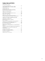
TABLE OF CONTENTS
INTRODUCTION
Refrigerator Safety ......................................................................................3
VARIANTS AND ACCESSORIES
42" Rise Models ..............................................................................................4
48" Rise Models .............................................................................................4
INSTALLATION REQUIREMENTS
Location Requirements ...........................................................................5
Electrical Requirements ..........................................................................6
Water Supply Requirements ................................................................7
Tipping Radius ...............................................................................................7
Product Dimensions ..................................................................................8
Door Swing Dimensions .........................................................................8
Stainless Steel Custom Side Panels .................................................14
INSTALLATION INSTRUCTIONS
Unpack the Refrigerator .........................................................................16
Reduce Tipping Radius
(if required) .......................................................................................................16
Move the Refrigerator into House ....................................................16
Install Anti-Tip Boards ...............................................................................17
Connect the Water Supply ....................................................................17
Plug in Refrigerator ....................................................................................20
Move Refrigerator to Final
Location ..............................................................................................................20
Level and Align Refrigerator ................................................................20
Install Overlay Series Custom Panels .............................................21
Adjust Doors ....................................................................................................22
Install Side Panel ..........................................................................................23
Install Base Grille ..........................................................................................23
Complete Installation ................................................................................24
Water System Preparation ....................................................................24

3
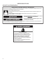
INTRODUCTION
REFRIGERATOR SAFETY
You can be killed or seriously injured if you don't immediately
You can be killed or seriously injured if you don't follow
All safety messages will tell you what the potential hazard is, tell you how to reduce the chance of injury, and tell you what can
happen if the instructions are not followed.
Your safety and the safety of others are very important.
We have provided many important safety messages in this manual and on your appliance. Always read and obey all safety
messages.
This is the safety alert symbol.
This symbol alerts you to potential hazards that can kill or hurt you and others.
All safety messages will follow the safety alert symbol and either the word “DANGER” or “WARNING.”
These words mean:
follow instructions.
instructions.
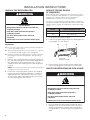
DANGER
WARNING
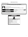
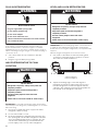
WARNING
Tip Over Hazard
Refrigerator is top heavy and tips easily when not
completely installed.
Keep doors taped closed until refrigerator is
completely installed.
Use two or more people to move and install
refrigerator.
Failure to do so can result in death or serious injury.

4
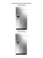
VARIANTS AND ACCESSORIES
42" RISE MODELS
JBSFS42NM and JBSSS42E22
48" RISE MODELS
JBSFS48NM and JBSSS48E22

5
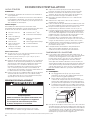
INSTALLATION REQUIREMENTS
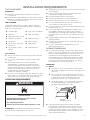
TOOLS AND PARTS
IMPORTANT:
Installer: Leave Installation Instructions with the
homeowner.
Homeowner: Keep Installation Instructions for future
reference. Save these Installation Instructions for the
local electrical inspector’s use.
TOOLS NEEDED:
Gather the required tools and parts before starting
installation. Read and follow the instructions provided
with any tools listed here.
Cordless drill Torx®† T27 screwdriver
Drill bits
Adjustable wrenches (2)
11/32" nut driver
Phillips screwdriver Appliance dolly
Small level 5/32" hex key
3/8" and 1/2" open-end
wrenches
Utility knife
1/4" and 5/16" socket
drivers
Tape measure
Parts Needed:
#8 x 3" (7.6 cm) wood screws (longer screws may be
needed) (6)
2" x 4" x 32" (5 cm x 10 cm x 81 cm) wood board(s)
(1 or 2)
Make custom panels or consult a qualified
cabinetmaker or carpenter to make the panels.
Overlay Series: Make custom panels, or consult a
qualified cabinetmaker or carpenter to make the
panels. See “Overlay Series Custom Panels and
Handle Kits” for more information.
Stainless is shipped complete.
If you are connecting the water line directly to copper
tubing and not to a shutoff valve, you need a ferrule, a
union, and a 1/4" (6.35 mm) compression fitting.
LOCATION REQUIREMENTS
IMPORTANT: This appliance is intended to be used in
household and similar applications such as:
Staff kitchen areas in shops, offices and other working
environments.
Farm houses and by clients in hotels, motels and
other residential type environments.
Bed and breakfast type environments.
Catering and similar non-retail applications.
Observe all governing codes and ordinances.
It is recommended that you do not install near an
oven, radiator, or other heat source.
Do not install in a location where the temperature will
fall below 55°F (13°C).
Floor must support the refrigerator weight, more
than 600 lbs (272 kg), door panels and contents of
the refrigerator. Flooring under refrigerator must be
at same level as the room. Face of cabinetry must be
plumb.
Ceiling height must allow for side tipping radius. See
"Tipping Radius."
Location should permit door to open fully. See “Door
Swing Dimensions.”
Location must permit top grille removal. See
“Opening Dimensions.”
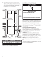
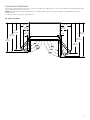
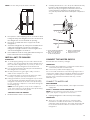
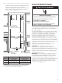
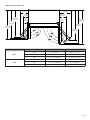
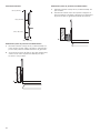
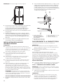
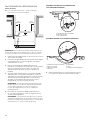
OPENING DIMENSIONS
To avoid tipping during use, the solid soffit must be
within 1" (2.5 cm) maximum above the refrigerator. If
the solid soffit is higher than 1" (2.5 cm) or one is not
available, then the refrigerator must be braced.
If anti-tip boards are needed, they must be installed
to the rear wall studs so that the bottom of the anti-
tip board is 84" (213 cm) from the floor. See “Install
Anti-Tip Boards” for more information.
IMPORTANT
NOTES:
A clearance of 1/2" (1.3 cm) must be maintained
above the top grille in order for the top grille to be
removed.
Do not remove the foam gasket from the top of
the compressor cover unless removal is necessary
to fit the unit under a soffit. Removal of the
gasket will cause loss in cooling efficiency.
If installing under a solid soffit, after, installation
raise the leveling legs so that the gasket is
pressed snugly against the soffit.
A grounded 3 prong electrical outlet should be
located within a specified number of inches from
the right-hand side cabinets or end panel. See the
chart following the graphic for the number of inches
required for your model. For more information, see
“Electrical Requirements.”
WARNING
Explosion Hazard
Keep flammable materials and vapors, such as
gasoline, away from appliance.
Use nonflammable cleaner.
Failure to do so can result in death, explosion, or fire.
A
B
A. Gasket
B. Compressor cover
1/2"
(1.3 cm)
†Torx and T27 are trademarks of Acument Intellectual Properties, LLC

6
The water shutoff should be located in the base
cabinet on either side of the refrigerator or some
other easily accessible area. If the water shutoff valve
is not in the cabinets, the plumbing for the water line
can come through the floor. See “Water Supply
Requirements” for more information.
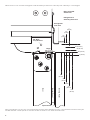
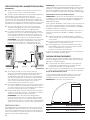
Model Width A
(as shown above)
Dimension B
(as shown above)
42 42" (106.7 cm) 7⁄2" (19.1 cm)
48 48" (121.9 cm) 13⁄2" (34.3 cm)
NOTE: Flooring under refrigerator must be at same level
as the room. Face of cabinetry must be plumb.
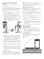
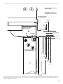
ELECTRICAL REQUIREMENTS
Before you move your refrigerator into its final location, it
is important to make sure you have the proper electrical
connection.
If the supply cord is damaged, it must be replaced
by the manufacturer or its service agent or a similar
qualified person. Do not use a cord that shows cracks or
abrasion damage along its length or at either the plug or
connection end.
RECOMMENDED GROUNDING METHOD
A 115 V, 60 Hz, AC only, 15 A or 20 A fused, grounded
electrical supply is required. It is recommended that a
separate circuit serving only your refrigerator be provided.
Use an outlet that cannot be turned off by a switch. Do
not use an extension cord.
IMPORTANT: If this product is connected to a GFCI
(Ground Fault Circuit Interrupter) protected outlet,
nuisance tripping of the power supply may occur,
resulting in loss of cooling. Food quality and flavor may
be affected. If nuisance tripping has occurred, and if the
condition of the food appears poor, dispose of it.
NOTE: Before performing any type of installation or
cleaning, remove the top grille and turn the master power
switch to OFF or disconnect power at the circuit breaker
box.
When you are finished, turn ON the master power switch
or reconnect power at the circuit breaker box. Then reset
the control to the desired setting.
A
B
Electrical Shock Hazard
Plug into a grounded 3 prong outlet.
Do not remove ground prong.
Do not use an adapter.
Do not use an extension cord.
Failure to follow these instructions can result in death,
fire, or electrical shock.
WARNING
77"
(196 cm)
6"
(15.2 cm)
6"
(15.2 cm)
24"
(60.96 cm) min.
6"
(15.2 cm)
1"
(2.54 cm)
80" - 90"
(203-229 cm)
83⁄2" (212.1 cm) min.
84⁄4" (215 cm) max.
to bottom of solid soffit
Width
(see chart following)
Dimension

7
WATER SUPPLY REQUIREMENTS
IMPORTANT:
All installations must meet local plumbing code
requirements.
Connect to potable water supply only.
Do not use with water that is microbiologically unsafe or
of unknown quality without adequate disinfection before
or after the system. Systems certified for cyst reduction
may be used on disinfected waters that may contain
filterable cysts.
There is not enough clearance to achieve a flush
installation if a water shutoff valve is located in the
wall behind the refrigerator.
The water shutoff should be located in the base
cabinet on either side of the refrigerator or some
other easily accessible area. The right-hand side is
recommended. The access hole through the cabinet
must be within 1/2" (1.3 cm) of the rear.
NOTE: If the water shutoff valve is in the back wall
behind the refrigerator, it must be at an angle so that
the tube is not kinked when the refrigerator is
pushed into its final location.
If the water shutoff valve is not in the cabinets, the
plumbing for the water line can come through the
floor. A 1/2" (12.7 mm) hole for plumbing should be
drilled at least 6" (15.2 cm) from the right-hand or
left-hand side cabinet or panel. On the floor, the hole
should be no more than 1" (2.54 cm) away from the
back wall. See “Connect the Water Supply.”
If additional tubing is needed, use copper tubing and
check for leaks. Install the copper tubing only in areas
where the household temperatures will remain above
freezing.
Do not use a piercing-type or 3/16" (4.76 mm) saddle
valve which reduces water flow and also clogs more
easily.
NOTE: Your refrigerator dealer has a kit available with
a 1/4" (6.35 mm) saddle-type shutoff valve, a union,
and copper tubing. Before purchasing, make sure a
saddle-type valve complies with your local plumbing
codes.
WATER PRESSURE
A cold water supply with water pressure between 30 and
120 psi (207 and 827 kPa) is required to operate the water
dispenser and ice maker. If you have questions about
your water pressure, call a licensed, qualified plumber.
NOTE: If the water pressure is less than what is required,
the flow of water from the water dispenser could
decrease or ice cubes could be hollow or irregular shaped.
If you have questions about your water pressure, call a
licensed, qualified plumber.
Reverse Osmosis Water Supply
IMPORTANT: The pressure of the water supply coming
out of a reverse osmosis system going to the water inlet
valve of the refrigerator needs to be between
30 psi and 120 psi (207 kPa and 827 kPa).
If a reverse osmosis water filtration system is connected
to your cold water supply, the water pressure to the
reverse osmosis system needs to be a minimum of 40 psi
to 60 psi (276 kPa to 414 kPa).
If the water pressure to the reverse osmosis system is less
than 40 psi to 60 psi (276 kPa to 414 kPa):
Check to see whether the sediment filter in the
reverse osmosis system is blocked. Replace the filter if
necessary.
Allow the storage tank on the reverse osmosis system
to refill after heavy usage.
If your refrigerator has a water filter, it may further
reduce the water pressure when used in conjunction
with a reverse osmosis system. Remove the water
filter cartridge.
If you have questions about your water pressure, call a
licensed, qualified plumber.
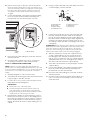
TIPPING RADIUS
Be sure there is adequate ceiling height to stand the
refrigerator upright when it is moved into place.
Be sure there is adequate ceiling height to stand the
refrigerator upright when it is moved into place.
If needed, the tipping radius can be reduced. See
“Reduce Tipping Radius.”
Side Tipping Radius
The side tipping radius varies depending upon the width
of the model. Use the chart provided to determine the
side tipping radius.
NOTE: Tip on side only.
Model Tipping Radius
42 93" (236.2 cm)
48 96" (243.8 cm)
A
6"
(15.2 cm)
6"
(15.2 cm)
1"
(2.54 cm)
6"
(15.2 cm)

8
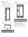
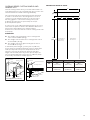
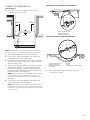
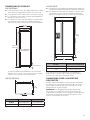
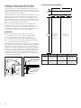
PRODUCT DIMENSIONS
SIDE VIEW
The depth from the front of the top grille to the back
of the refrigerator cabinet is 25⁄8" (64.5 cm).
The power cord is 84" (213 cm) long.
The water line attached to the back of the refrigerator
is 5 ft (1.5 m) long.
Height dimensions are shown with leveling legs
extended 1/8" (3 mm) below the rollers.
*When leveling legs are fully extended to 1⁄4"
(3.2 cm) below rollers, add 1⁄8" (2.9 cm) to the height
dimensions.
TOP VIEW
Model A B
42 Rise 41" (104.1 cm) 26⁄8" (6.67 cm)
48 Rise 47" (119.4 cm) 26⁄8" (6.67 cm)
FRONT VIEW
Width dimensions were measured from trim edge to
trim edge.
Height dimensions are shown with leveling legs
extended 1/8" (3 mm) below the rollers.
Model Tipping Radius A
42 42⁄" (107.5 cm)
48 48⁄" (122.8 cm)
*When leveling legs are fully extended to 1⁄4" (3.2 cm)
below rollers, add 1⁄8" (2.9 cm) to the height dimensions.
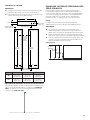
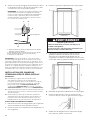
DOOR SWING DIMENSIONS
The location must permit both doors to open to a
minimum of 90°. Allow 5" (12.7 cm) minimum space
between the side of the refrigerator and a corner wall.
NOTE: More clearance may be required if you are using
overlay panels, custom handles, or extended handles.
To adjust the door swing, see “Adjust Doors.”
A
B
A
*83⁄8"
(211.8 cm)
*83⁄8"
(211.8 cm)
25⁄8"
(64.5 cm)
84" (213.4 cm)
Power Cord
25⁄8"
(64.5 cm)
23⁄2"
(59.7 cm)
*3⁄2" (8.9 cm)
(see chart following)

9
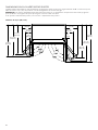
DOOR SWING DIMENSIONS
The location must permit both doors to open to a minimum of 90°. Allow 5" (12.7 cm) minimum space between the side
of the refrigerator and a corner wall.
NOTE: More clearance may be required if you are using overlay panels, custom handles, or extended handles on a
Classic model.
To adjust the door swing, see “Adjust Doors.”
42" (106.7 cm) Models
43/8"
(110.8 cm)
15/4"
(40 cm)
12/2"
(31.8 cm)
40/8"
(101.9 cm)
42/16"
(109.1 cm)
45/2"
(115.5 cm)
5"
(12.7 cm)
14/16"
(36.7 cm)
19/16"
(50 cm)
5"
(12.7 cm)
50/16"
(128.7 cm)
49/2"
(125.8 cm)

10
48" (121.9 cm) Models
Product Size Door Opening Angle Distance (A) right side Distance (B) left side
90° 5" (12.7 cm) 5" (12.7 cm)
42" 110° 143/16" (36.1 cm) 1115/16" (30.3 cm)
130° 189/16" (47.1 cm) 145/16" (36.3 cm)
90° 5" (12.7 cm) 5" (12.7 cm)
48" 110° 147/16" (36.7 cm) 153/4" (40 cm)
130° 1911/16" (50 cm) 121/2" (31.8 cm)
43/8"
(110.8 cm)
42/16"
(109.1 cm)
40/8"
(101.9 cm)
12/2"
(31.8 cm)
50/16"
(128.7 cm)
49/2"
(125.8 cm)
45/2"
(115.5 cm)
19/16"
(50 cm)
14/16"
(36.7 cm)
15/4"
(40 cm)
5"
(12.7 cm)
5"
(12.7 cm)

11
OVERLAY SERIES DOOR PANEL AND CABINETRY CLEARANCE
The custom door panels and adjacent cabinetry must be designed so that there is sufficient clearance for the doors to
swing open. If the refrigerator is to be installed close to the wall, see “Door Swing 90°” on next page.
1/2"
(3.8 cm)
1/4"
(3.2 cm)
1"
(2.5 cm)
Door Swing 110°
Actual Size
Refrigerator to
Cabinetry Clearance
Refrigerator
Side Trim
Cabinetry
Hinge
Overlay Panel
Backer Panel
Spacer Panel
Door
NOTE: Allow 1/2"
(1.3 cm) clearance
between overlay
panel and cabinetry.
NOTE: For overlay Series models, rout the hinge
side of the custom door panels to a radius that is
equal to atleast half the thickness of the panel if
a 130° door swing is desired. See "Adjust Doors."
1/4" (6.35 mm)
1/2"
(13 mm)
1/2" (13 mm)
3/4" (19 mm)
1" (25 mm)
1"
(25 mm)
1/4"
(32 mm)
1/2"
(38 mm)
3/4"
(19 mm)

12
When the doors are closed the refrigerator will extend beyond the face of the adjacent cabinetry to some degree.
Allow a minimum of 5" (12.7 cm) of space between the side of the refrigerator and a corner wall. More clearance may be
needed if thicker custom panels or custom handles are used. Do not overlook baseboards.
Refrigerator to
Cabinetry Clearance
Door Swing 90°
Actual Size
Refrigerator
Side Trim
Cabinetry
90° Door
Stop Position
Hinge
Door
Backer Panel
Overlay Panel
Spacer Panel
1/2"
(38 mm)
1/2"
(13 mm)
3/4"
(19 mm)
1"
(25 mm)
1/4"
(32 mm)
3/4"
(19 mm)
1/2"
(13 mm)
1"
(25 mm)
1/4" (6.35 mm)
3/4" (19 mm)
1/2" (13 mm)
1" (25 mm)

13
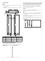
OVERLAY SERIES CUSTOM PANELS AND
HANDLE KITS
Custom overlay panels allow you to blend the exterior of
your refrigerator into the overall kitchen décor, and to use
custom handles for additional design flexibility.
The custom panels must have backer panels attached
in order to mount them to the refrigerator. It is most
common to work with three panels, as shown in the
following graphic: a decorative overlay panel, a 1/8"
(3.18 mm) spacer panel or spacer strips and a 1/4"
(6.35 mm) backer panel.
In some cases, your cabinet manufacturer may choose to
work with one panel routed for the different dimensions.
Follow these panel dimension and placement
instructions to be sure that the custom overlay panels will
fit properly.
IMPORTANT:
The weight of the refrigerator door overlay panel
cannot exceed 50 lbs (23 kg).
The weight of the freezer door overlay panel cannot
exceed 40 lbs (18.1 kg).
The weight of the top grille overlay panel cannot
exceed 10 lbs (4.5 kg).
To minimize panel weight, you may use 2" (5.08 cm)
spacer strips around the perimeter in place of full-sheet
solid spacer panels. The spacer strips must be set in
at least 1" (2.54 cm) from the top, bottom and sides
edges of the backer panel. If you use spacer strips, it is
also recommended that you use two 2" (5.08 cm) strips
horizontally centered for added support.
DECORATIVE OVERLAY PANEL
Model A B C
42 171⁄8"
(43.47 cm)
231⁄8"
(58.71 cm)
401⁄2"
(102.81 cm)
48 195⁄8"
(49.82 cm)
265⁄8"
(67.60 cm)
461⁄2"
(118.05 cm)
B
A
C
Overlay Panel
Overlay Panel
Spacer Panel
Spacer Panel
Backer Panel
Backer Panel
Offset Dimension
Door/Grille
Trim
1" minimum
(25 mm)
1/8"
(3.18 mm)
1/4"
(6.35 mm)
1/8"
(3.18 mm)
5/8" to 3/4"
(15.88 to
19.05 mm)
Grille Panel
Freezer Door
Panel (Non-
Dispenser)
Refrigerator
Door Panel
7/4"
(18.4 cm)
72/4"
(183.5 cm)

14
BACKER PANELS
NOTE:
Dashed lines represent placement of backer panels on
overlay panels.
Illustration shows backer panels placed on decorative
overlays.
Model D E F
42 165⁄8"
(42.20 cm)
225⁄8"
(57.44 cm)
391⁄2"
(100.27 cm)
48 191⁄2"
(48.55 cm)
261⁄2"
(66.33 cm)
451⁄2"
(115.51 cm)
OVERLAY SERIES DOOR HANDLE KITS
The following handle style is available. Contact your
KitchenAid dealer or KitchenAid Parts and Accessories at
1-800-442-9991. In Canada, call 1-800-807-6777.
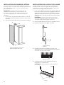
STAINLESS SERIES CUSTOM SIDE PANELS
Custom side panels may be needed when not enough
space is available to have cabinets on both sides of the
refrigerator or when the refrigerator is placed at the
end of a cabinet run. You may choose an Inset, Flush, or
Recessed Inset panel installation.
BACKER
The width and height of a side panel are determined by
the type of installation you are planning.
NOTE:
The dimensions shown are actual product dimensions
and may not reflect the needed panel installation
dimensions.
The side panel should be a minimum of 1/2" (1.27 cm)
thick to avoid warping.
If the opening depth is 25" (63.5 cm) or more, you may
want to install a support board on rear wall.
Refrigerator
D E
F
70/2"
(179.1 cm)
70/2"
(179.1 cm)
Bottom Offset
13/16" (2.1 cm)
Handle
Side Offset
1/4"
(6.4 mm)
Top Offset
1/8" (4.13 cm)
Bottom Offset
1/2" (12.7 mm)
Side Offset
1/2" (12.7 mm)
6/16" (15.7 cm)
Knurl grip handle with chrome endcaps - W10782873
23/32"
(59.9 cm)
23/32"
(59.8 cm)
23/32"
(59.6 cm)

15
Side Trim
Inset Installation Dimensions
1. Measure the distance from point A (as shown) to the
back wall. Add 1/16" (1.6 mm) to this measurement to
allow the side panel to fit into the trim.
2. If the panel is more than 11/32" (8.7 mm) thick, route
the front edge to allow the side panel to fit into the
trim.
Inset Installation Dim
1. Measure the distance from point A (as shown) to back
wall.
2. Route the front edge of the support board or attach
a 3/8" (9.5 mm) board to hold the panel in the cabinet
side trim.
A
A
11/16" (18 mm)
1/2" (12.2 mm)
9/16" (13.9 mm)
5/8" (15.7 mm)

16
INSTALLATION INSTRUCTIONS
UNPACK THE REFRIGERATOR
IMPORTANT:
Do not remove the film covering until the refrigerator
is in its operating location.
All four leveling legs must contact the floor to support
and stabilize the full weight of the refrigerator.
Keep the cardboard shipping piece or plywood under
the refrigerator until it is installed in the operating
location.
1. Remove and save the literature package bag taped to
the side of the refrigerator and the parts bag behind
the grille. Remove the four brackets (two on each
side) that attach the shipping base to the refrigerator
bottom.
NOTE: Do not remove tape and door bracing until the
refrigerator is in its final location.
2. If necessary, reduce the tipping radius. See “Tipping
Radius” for ceiling height requirements or “Reduce
Tipping Radius” for step-by-step instructions. If you
do not need to reduce the tipping radius, proceed to
“Move the Refrigerator into House.”
REDUCE TIPPING RADIUS
(IF REQUIRED)
Before bringing the refrigerator into the home, be sure
there is adequate ceiling height to stand the refrigerator
upright. See “Tipping Radius” in the “Installation
Requirements” section for more information.
If you do not have adequate ceiling height to stand the
refrigerator upright, the tipping radius can be reduced by
removing the top grille and side trims (see the following
chart).
Model Reduced Tipping Radius
42 90⁄2" (229.9 cm)
48 91⁄4" (231.8 cm)
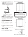
1. Grasp both ends of the top grille.
2. Push the top grille straight up; then pull straight out.
Lay the grille on a soft surface.
3. Remove the 6 screws attaching each cabinet side
trim to the refrigerator and remove the side trims.
MOVE THE REFRIGERATOR INTO HOUSE
1. Place an appliance dolly under the left side of the
refrigerator as shown. Place the corner posts from
the packing materials over the trims and handles
as appropriate to avoid damage. Slowly tighten the
strap.
WARNING
Tip Over Hazard
Refrigerator is top heavy and tips easily when not
completely installed.
Keep doors taped closed until refrigerator is
completely installed.
Use two or more people to move and install
refrigerator.
Failure to do so can result in death or serious injury.
AB
B
A. Top grille
B. Cabinet side trim
WARNING
Tip Over Hazard
Refrigerator is top heavy and tips easily when not
completely installed.
Keep doors taped closed until refrigerator is
completely installed.
Use two or more people to move and install
refrigerator.
Failure to do so can result in death or serious injury.

17
NOTE: Pass the dolly strap under the handles.
2. Place pieces of the shipping carton on the floor when
rolling the dolly and refrigerator into the house. Move
the refrigerator close to the built-in opening.
3. Place top of cardboard carton or plywood under
refrigerator.
4. Stand the refrigerator up. First, place the left bottom
edge of the refrigerator on the floor, stand the
refrigerator upright and then lower the right-hand
side of the refrigerator to the floor.
5. Reassemble the trim and top grille after the dolly has
been removed from the refrigerator.
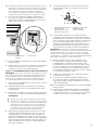
INSTALL ANTI-TIP BOARDS
IMPORTANT:
To avoid tipping during use, the solid soffit must be
within 1" (2.5 cm) maximum above the refrigerator. If
the solid soffit is higher than 1" (2.5 cm) or one is not
available, then the refrigerator must be braced.
It is recommended that board(s) be installed before
the refrigerator is installed.
Board(s) must be long enough to fully cover the
width of the compressor cover.
Locate the board(s) so the bottom surface(s) of the
board(s) is (are) 84" (213 cm) from the floor.
During installation, raise the refrigerator up so there
is 1/4" (6.35 mm) maximum between the top of the
refrigerator and the bottom of the anti-tip board(s).
Do not crush the compressor cover when raising the
rear leveling legs.
NOTE: The foam gasket, on top of the compressor
cover, will compress to fit under the anti-tip board(s).
There is no need to trim the gasket.
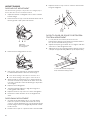
TO INSTALL ANTITIP BOARDS
1. Mark the stud locations on rear wall.
2. Securely attach two 2" x 4" x 32" (5 cm x 10 cm x 81 cm)
boards to wall studs behind refrigerator. Use six
#8 x 3" (7.6 cm) (or longer) wood screws. The wood
screws must be screwed into the studs at least
1½" (3.8 cm). The boards must overlap the compressor
cover.
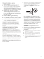
CONNECT THE WATER SUPPLY
Read all directions before you begin.
IMPORTANT:
If you turn the refrigerator on before the water line is
connected, turn the ice maker OFF.
Connect to potable water supply only.
Do not use with water that is microbiologically unsafe or
of unknown quality without adequate disinfection before
or after the system. Systems certified for cyst reduction
may be used on disinfected waters that may contain
filterable cysts.
CONNECT TO WATER LINE
PARTS NEEDED
Minimum 7 ft (2.13 m) flexible, codes-approved water
supply line
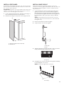
STYLE 1SHUTOFF VALVE CONNECTION
NOTE: If your water line connection does not look like
Style 1, see “Style 2—Copper Line Connection.”
1. Unplug refrigerator or disconnect power supply.
IMPORTANT:
There is not enough clearance to achieve a flush
installation if a water shutoff valve is located in the
wall behind the refrigerator. The water shutoff should
be located in the base cabinet on either side of the
refrigerator.
2" (5 cm)
AB
C
D
A. Center board 1/4" (6.35 mm)
max. above refrigerator
B. Two 2" x 4" x 32" (5 cm x
10 cm x 81 cm) boards
C. Attach to studs with six
#8 x 3" (7.6 cm) screws
D. Compressor cover
2" (5 cm)

18
Before attaching the tubing to shutoff valve, flush
the main water supply line to remove particles and
air in the water line. Allow enough flow so that water
becomes clear. Flushing the water line may help
avoid filters and/or water valves from becoming
clogged.
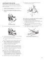
2. Connect the flexible, codes-approved water supply
line to the water shutoff valve by threading the
provided nut onto the shutoff valve as shown.
3. Place the end of the tubing into a bucket, and turn
shutoff valve ON.
4. Check for leaks. Tighten any nuts or connections
(including connections at the valve) that leak.
STYLE 2COPPER LINE CONNECTION
NOTE: If there is a water supply line that meets the
specifications in “Water Supply Requirements,” proceed
to “Connecting to Refrigerator.” If not, use the following
instructions to connect to the household cold water
supply.
1. Unplug refrigerator or disconnect power.
2. Turn OFF main water supply. Turn ON nearest faucet
long enough to clear line of water.
3. Locate a 1/2" to 1⁄4" (1.3 cm to 3.18 cm) vertical cold
water pipe near the refrigerator.
IMPORTANT:
Make sure it is a cold water pipe.
Horizontal pipe will work, but drill on the top
side of the pipe, not the bottom. This will help
keep water away from the drill and keep normal
sediment from collecting in the valve.
4. Determine the length of copper tubing you need.
Measure from the connection on the refrigerator to
the water pipe. Add 7 ft (2.1 m) to allow for cleaning.
Use 1/4" (6.35 mm) O.D. (outside diameter) copper
tubing. Be sure both ends of copper tubing are cut
square.
5. Using a cordless drill, drill a 1/4" (6.35 mm) hole in the
cold water pipe you have selected.
6. Fasten the shutoff valve to the cold water pipe with
the pipe clamp. Be sure the outlet end is solidly in
the 1/4" (6.35 mm) drilled hole in the water pipe and
that the washer is under the pipe clamp. Tighten the
packing nut. Tighten the pipe clamp screws slowly
and evenly so washer makes a watertight seal. Do not
overtighten.
IMPORTANT: Before attaching the tubing to shutoff valve,
flush the main water supply line to remove particles and
air in the water line. Allow enough flow so that water
becomes clear. Flushing the water line may help avoid
filters and/or water valves from becoming clogged.
7. Slip the compression sleeve and compression nut
on the copper tubing as shown. Insert the end of
the tubing into the outlet end squarely as far as it
will go. Screw compression nut onto outlet end with
adjustable wrench. Do not overtighten the clamp or
the sleeve. This will crush the copper tubing.
8. Turn off the shutoff valve on the water pipe. Coil the
copper tubing.
9. Connect the flexible, codes-approved water supply
line to the water shutoff valve by threading the
provided nut onto the shutoff valve.
10. Place the end of the tubing into a bucket, and turn
shutoff valve ON.
11. Check for leaks around the saddle valve. Tighten any
nuts or connections (including connections at the
valve) that leak.
A
B
C
A. Bulb
B. Nut
C. Water tubing
A
B
C
D
E
F
G
A. Cold water pipe
B. Pipe clamp
C. Copper tubing
D. Compression nut
E. Compression sleeve
F. Shutoff valve
G. Packing nut

19
CONNECT TO REFRIGERATOR
Parts Supplied
1/4" to 1/4" (6.35 mm to 6.35 mm) male-to-male
coupling (on some models)
NOTE: The flexible, codes-approved water supply line
should connect to the supply valve through the floor.
1. Unplug the refrigerator or disconnect power.
2. Connect the 7 ft (2.13 m) flexible codes-approved
water tube to the water supply valve.
3. Flush the main water supply line to remove particles
and air in the water line. Allow enough flow so that
water becomes clear
4. Tape the 7 ft (2.13 m) flexible codes-approved water
supply line to the floor, 7" (17.78 cm) from the left
side of the refrigerator. Tape along the length of
the tubing, which will allow it to pass beneath the
refrigerator without interference.
NOTE: Allow a minimum of 26" (66.04 cm) of flexible
codes-approved water supply line to be loose at
the front of the refrigerator for connecting to the
refrigerator.
5. Connect the 7 ft (2.13 m) flexible codes-approved
water supply line to the refrigerator.
NOTE: If the main water shutoff valve is behind the
refrigerator, a secondary water shutoff valve may be
installed in line with the water supply line at the front
of the product.
OVERMOLD COUPLING ON SOME MODELS
DISCRETE COUPLING ON SOME MODELS
6. Turn on the water supply valve and check all
connections for leaks.
AB C
A. Household water line
B. Nut (purchased)
C. Ferrule (purchased)
ABCD
EFG
A. Household water line
B. Nut (purchased)
C. Ferrule (purchased)
D. Coupling
E. Bulb
F. Nut
G. Refrigerator water tubing
6"
(15.2 cm)
6"
(15.2 cm)
1"
(2.54 cm)
7"
(17.78 cm)

20
PLUG IN REFRIGERATOR
If the supply cord is damaged, it must be replaced
by the manufacturer or its service agent or a similar
qualified person. Do not use a cord that shows cracks or
abrasion damage along its length or at either the plug or
connection end.
1. Set control switch at top of cabinet to the OFF
position.
2. Plug into a grounded 3 prong outlet.
MOVE REFRIGERATOR TO FINAL
LOCATION
IMPORTANT: To avoid floor damage, make sure levelers
are raised (not touching floor) and refrigerator is on rollers
before moving.
1. Place top of cardboard carton or plywood under
refrigerator. Remove dolly.
2. Do not remove film or cover.
3. Move the refrigerator straight back and evenly into
the opening. Be sure that the refrigerator side trims
are not interfering with the door opening. Also, be
sure that the water tubing is not kinked and the
power supply cord is on top of the refrigerator.
LEVEL AND ALIGN REFRIGERATOR
IMPORTANT: All four leveling legs must contact the floor
to support and stabilize the full weight of refrigerator.
Rollers are for moving the refrigerator, not for permanent
support.
After moving the refrigerator to its final location:
1. Use a 5/16" socket driver to turn the leveling bolts
clockwise to extend the legs to the floor as shown.
The rollers should be off the floor.
2. Adjust the leveling legs to level and align the
refrigerator from left to right and front to back so
that the refrigerator is level and aligned with the
cabinetry. The cabinetry surface must be plumb for
the ideal fit of the refrigerator side trim.
Electrical Shock Hazard
Plug into a grounded 3 prong outlet.
Do not remove ground prong.
Do not use an adapter.
Do not use an extension cord.
Failure to follow these instructions can result in death,
fire, or electrical shock.
WARNING
WARNING
Tip Over Hazard
Refrigerator is top heavy and tips easily when not
completely installed.
Keep doors taped closed until refrigerator is
completely installed.
Use two or more people to move and install
refrigerator.
Failure to do so can result in death or serious injury.
WARNING
Tip Over Hazard
Refrigerator is top heavy and tips easily when not
completely installed.
Keep doors taped closed until refrigerator is
completely installed.
Use two or more people to move and install
refrigerator.
Failure to do so can result in death or serious injury.
A
A
BB
A. Rear leveling bolt
B. Front leveling bolt
La page est en cours de chargement...
La page est en cours de chargement...
La page est en cours de chargement...
La page est en cours de chargement...
La page est en cours de chargement...
La page est en cours de chargement...
La page est en cours de chargement...
La page est en cours de chargement...
La page est en cours de chargement...
La page est en cours de chargement...
La page est en cours de chargement...
La page est en cours de chargement...
La page est en cours de chargement...
La page est en cours de chargement...
La page est en cours de chargement...
La page est en cours de chargement...
La page est en cours de chargement...
La page est en cours de chargement...
La page est en cours de chargement...
La page est en cours de chargement...
La page est en cours de chargement...
La page est en cours de chargement...
La page est en cours de chargement...
La page est en cours de chargement...
La page est en cours de chargement...
La page est en cours de chargement...
La page est en cours de chargement...
La page est en cours de chargement...
-
 1
1
-
 2
2
-
 3
3
-
 4
4
-
 5
5
-
 6
6
-
 7
7
-
 8
8
-
 9
9
-
 10
10
-
 11
11
-
 12
12
-
 13
13
-
 14
14
-
 15
15
-
 16
16
-
 17
17
-
 18
18
-
 19
19
-
 20
20
-
 21
21
-
 22
22
-
 23
23
-
 24
24
-
 25
25
-
 26
26
-
 27
27
-
 28
28
-
 29
29
-
 30
30
-
 31
31
-
 32
32
-
 33
33
-
 34
34
-
 35
35
-
 36
36
-
 37
37
-
 38
38
-
 39
39
-
 40
40
-
 41
41
-
 42
42
-
 43
43
-
 44
44
-
 45
45
-
 46
46
-
 47
47
-
 48
48


Jenn-Air JBSS48E22L Manuel utilisateur
- Catégorie
- Frigos
- Taper
- Manuel utilisateur
- Ce manuel convient également à
dans d''autres langues
- English: Jenn-Air JBSS48E22L User manual
Documents connexes
-
Jenn-Air JF42SSFXDA00 Guide d'installation
-
Jenn-Air Refrigerator W10183782A Manuel utilisateur
-
-
-
-
Jenn-Air JS42CXFXDB Guide d'installation
-
Jenn-Air JS42SEDUDW20 Guide d'installation