BLACK DECKER BPACT08WT PORTABLE AIR CONDITIONER Remote Control Manuel utilisateur
- Taper
- Manuel utilisateur

INSTRUCTION MANUAL
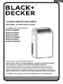
PORTABLE AIR CONDITIONER
Thank you for choosing BLACK+DECKER!
PLEASE READ BEFORE RETURNING THIS PRODUCT FOR
ANY REASON.
If you have a question or experience a problem with your BLACK+DECKER
purchase, go to www.blackanddecker.com/instantanswers
If you can’t find the answer or do not have access to the Internet, call
844-299-0879 from 10:30 a.m. to 6:30 p.m. EST Mon. - Fri. to speak with an
agent. Please have the catalog number available when you call.
SAVE THIS MANUAL FOR FUTURE REFERENCE.
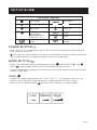
CATALOG NUMBER
BPACT08WT
BPACT10WT
BPACT12WT
BPACT12HWT
BPACT14WT
BPACT14HWT

Page 2
Thank you for purchasing our
BLACK+DECKER product. This
easy-to-use manual will guide you
in getting the best use of your air
conditioner.
Remember to record the model
and serial numbers. They are on a
label on the rear.
Staple your receipt to your manual.
You will need it to obtain warranty service.
Model number
Serial number
Date of purchase
PRODUCT REGISTRATION
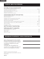
CONTENTS
SAFETY INFORMATION
Important Safety Instructions ..........................................................................................................................................3-4
Grounding Instructions ......................................................................................................................................................... 5
LCDI Power Cord and Plug ..................................................................................................................................6
Safety Guidelines .................................................................................................................................................... 7
Operating Conditions ............................................................................................................................................ 8
SET UP & USE
Parts & Features .......................................................................................................................................................................9
Installation Guide .................................................................................................................................................. 10
Window Slider Kit Installation ............................................................................................................................11
Exhaust Hose Installation ....................................................................................................................................12
Control Panel ...........................................................................................................................................................13
Operating from the Control Panel .............................................................................................................13-14
Operating from the Remote Control .............................................................................................................. 15
Remote Control ................................................................................................................................................16-19
Water Drainage ...............................................................................................................................................20-21
CLEANING & CARE .............................................................................................................................................22
TROUBLESHOOTING & WARRANTY
Before You Call For Service ..............................................................................................................................23
Customer Service .................................................................................................................................................. 23
Troubleshooting ....................................................................................................................................................24
Limited Warranty ...................................................................................................................................................................25

Page 3
SAFETY INFORMATION
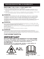
IMPORTANT SAFETY INSTRUCTIONS
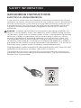
1. To reduce risk of injury, read this guide before using the appliance.
2. Air conditioner must be connected to proper electrical outlet with the correct
electrical outlet with the correct electrical supply.
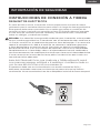
3. Proper grounding must be ensured to reduce the risk of shock and re. DO NOT
CUT OR REMOVE THE GROUNDING PRONG. If you do not have a three-prong
electric receptacle outlet in the wall, have a certied electrician install the proper
receptacle. The wall receptacle MUST be properly grounded.
4. Do not operate air conditioner if power cord is frayed or otherwise damaged.
Avoid using it if there are any cracks or abrasion damage along the length, plug
connector or if the unit malfunctions or is damaged in any manner. Contact an
authorized service technician for examination, repairs or adjustments.
5. DO NOT USE AN ADAPTER OR AN EXTENSION CORD.
6. Do not block airow around the air conditioner. The exhaust hose should be free
of any obstructions.
7. Always unplug the air conditioner before servicing or moving the unit.
8. Do not install or use the air conditioner in any area where the atmosphere
contains combustible gases or where the atmosphere is oily or sulphurous. Avoid
any chemical coming in contact with your air conditioner.
9. Do not place any object on the top of the unit.
10. Never operate the air conditioner without lters in place.
11. Do not use the air conditioner near a bathtub, shower or wash basin.
12. This appliance is not intended for use by persons (including children) with
reduced physical sensory or mental capabilities or lack of experience &
knowledge, unless they have been given supervision or instruction concerning
use of the appliance by a person responsible for their safety.
13. Children should be supervised to ensure that they do not play with the appliance.
14. If the SUPPLY CORD is damaged, it must be replaced by the manufacturer, a
service agent or similarly qualied persons in order to avoid a hazard.
15. The air conditioner shall be installed in accordance with national wiring
regulations.
WARNING
WARNING - Hazards or unsafe
practices which COULD result in
severe personal injury or death
DANGER
DANGER - Immediate hazards
which WILL result in severe
personal injury or death
CAUTION
CAUTION - Hazards or unsafe
practices which COULD result in
minor personal injury
WARNING
When using electrical appliances, basic safety precautions
should be followed, including the following

Page 4
HANDLING ALKALINE BATTERIES
1. Should uid from the battery accidentally get into your eyes, there is a threat
of loss of eyesight, do not rub them. Immediately rinse your eyes with clean tap
water and then consult a physician immediately.
2. Do not put the battery in a re, expose it to heat, dismantle or modify it. If the
insulation or safety valve is damaged, the battery may leak uid, overheat or
explode.
3. Do not insert the battery with the poles reversed. Doing so may cause some
abnormality or a short and the battery may leak uid, overheat or explode.
4. Keep the battery out of the reach of children. If the battery is swallowed, contact
a physician immediately.
5. If the alkali uid gets in your mouth, rinse your mouth with water and contact a
physician immediately.
6. If the alkali uid gets on your skin or clothes, it may burn your skin, thoroughly
rinse the affected area with tap water.
7. Do not mix new and old batteries or other makes of batteries. The different
attributes may cause the battery to leak uid, overheat or explode.
8. This battery was not made to be recharged. Recharging this battery may damage
the insulation or internal structure and may cause the battery to leak uid,
overheat or explode.
9. Do not damage or remove the label on the exterior of the battery. Doing so may
cause the battery to short, leak uid, overheat or explode.
10. Do not drop, throw or expose the battery to extreme impact. Doing so may cause
the battery to leak uid, overheat or explode.
11. Do not alter the shape of the battery. If the insulation or safety valve is damaged,
the battery may leak uid, overheat or explode.
12. Immediately remove batteries when they have lost all power. Leaving the
batteries in the unit for a long time may cause the batteries to leak uid, overheat
or explode due to gas that is generated by the batteries.
13. Remove the batteries from the unit when not using the unit for an extended
period of time. The batteries may leak uid, overheat or explode due to gas that is
generated by the batteries.
14. Do not apply solder directly to the batteries. The heat may cause the batteries to
leak uid, overheat or explode.
15. Do not get the batteries wet. Doing so may cause the batteries to overheat.
16. Store batteries someplace out of direct sunlight where the temperature and
humidity are not high. Not doing so may cause the batteries to leak uid,
overheat or explode. Also, it may cause the life and performance of the batteries
to decline.
17. Follow the regulations of the local government when disposing of these batteries.
18. NEVER mix alkaline, standard (carbon-zinc), rechargeable (nickel-cadmium)
batteries with this product.
SAVE THESE INSTRUCTIONS
HOUSEHOLD USE ONLY
WARNING
When handling alkaline batteries, basic safety precautions
should be followed, including the following
SAFETY INFORMATION

Page 5
GROUNDING INSTRUCTIONS
ELECTRICAL REQUIREMENTS
In the event of malfunction or breakdown, grounding provides a path of least
resistance for electric current to reduce the risk of electric shock. The appliance
must be connected to a cord having an equipment-grounding conductor and
a grounding plug. The plug must be plugged into an appropriate outlet that
is properly installed and grounded in accordance with all local codes and
ordinances.
DANGER - Improper connection of the equipment grounding conductor can
result in a risk of electric shock. The conductor with insulation having an outer
surface that is green with or without yellow stripes is the equipment grounding
conductor. If repair or replacement of the cord or plug is necessary, do not
connect the equipment-grounding conductor to a live terminal. Check with
a qualified electrician or service person if the grounding instructions are not
completely understood, or if in doubt as to whether the appliance is properly
grounded. Do not modify the plug connected to the appliance – if it will not fit
the outlet, have a proper outlet installed by a qualified electrician.
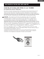
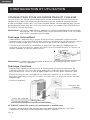
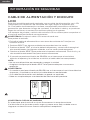
FOR GROUNDED, CORD-CONNECTED APPLIANCE RATED LESS THAN 15A AND
INTENDED FOR USE ON A NOMINAL 120V SUPPLY CIRCUIT
The appliance is for use on a nominal 120V circuit and should be connected to a
grounding outlet that looks like the one illustrated below. The use of a temporary
adapter is not recommended.
SAFETY INFORMATION

Page 6
SAFETY INFORMATION
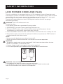
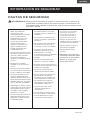
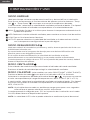
LCDI POWER CORD AND PLUG
This air conditioner is equipped with an LCDI (Leakage Current Detection and
Interruption) power cord that is required by UL. This power supply cord contains
state-of-the-art electronics that sense leakage current. If the cord is damaged
and leakage occurs, power will be disconnected from the unit.
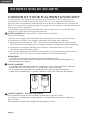
The test and reset buttons on the LCDI Plug are used to check if the plug is
functioning properly.
WARNING: Test LCDI before each use.
To test the plug:
1. Plug power cord into a grounded 3-prong outlet.
2. Press RESET (on some units a green light will turn on).
3. Press the TEST button, the circuit should trip and cut all power to the air
conditioner (on some units green light may turn off).
4. Press the RESET button for use. You will hear a click and the A/C is ready for use.
5. The power supply cord must be replaced if it fails to trip when the TEST button is
pressed and the unit fails to reset.
NOTE:
• Do not use this device to turn the unit on or o.
• Always make sure the reset button is pushed in for correct operation.
WARNING:
• The power supply cord must be replaced if it fails to reset when either the test
button is pushed, or it cannot be reset.
• If power supply cord is damaged, it cannot be repaired.
• It must be replaced by one obtained from the product manufacturer.
WARNING- RISK OF FIRE
It is important the plug fits tightly into the wall outlet.
If the plug does not fit securely and appears loose, it should not be used.
Have a licensed electrician replace the receptacle.

Page 7
SAFETY GUIDELINES
WARNING: To prevent injury to the user or other people and property
damage, the following instructions must be followed. Incorrect
operation due to ignoring of instructions may cause harm or
damage.
• Your air conditioner
should be used in such a
way that it is protected
from moisture. e.g.
condensation, splashed
water, etc. Do not place or
store your air conditioner
where it can fall or be
pulled into water or any
other liquid. Unplug
immediately.
• Always transport your air
conditioner in a vertical
position and stand on a
stable, level surface during
use.
• Turn off the product when
not in use.
• Always use the switch on
the control panel to start or
shut off the unit.
• Always contact a qualied
person to carry out
repairs. If the supply cord
is damaged it must be
repaired by a qualied
technician.
• Keep an air path of at least
12 inches all around the unit
from walls, furniture and
curtains.
• If the air conditioner is
knocked over during use,
turn off the unit and unplug
from the power supply
immediately.
• Do not operate your air
conditioner in a wet room
such as a bathroom or
laundry room.
• Do not touch the unit with
wet or damp hands or when
barefoot.
• Do not press the buttons
on the control panel with
anything other than your
ngers.
• Do not remove any xed
covers. Never use this
appliance if it is not working
properly, or if it has been
dropped or damaged.
• Never use the plug to start
and stop the unit.
• Always use the switch on the
control panel to start or shut
off the unit.
• Do not cover or obstruct the
inlet or outlet grilles.
• Do not use hazardous
chemicals to clean or come
into contact with the unit.
Do not use the unit in the
presence of inammable
substances or vapor such as
alcohol, insecticides, petrol,
etc.
• Do not allow children
to operate the unit
unsupervised.
• Do not use this product for
functions other than those
described in this instruction
manual.
• Use the unit in the
recommended room size.
8,000 BTU up to 350 sq. ft.
10,000 BTU up to 450 sq. ft.
12,000 BTU up to 550 sq. ft.
14,000 BTU up to 700 sq. ft.
• Locate the unit where
furniture cannot obstruct
the air ow.
• Keep blinds/curtains
drawn.
• Keep the lters clean.
• Keep doors and windows
closed to keep cool air in
and warm air out.
SAFETY INFORMATION

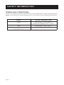
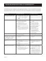
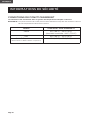
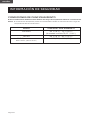
OPERATING CONDITIONS
The air conditioner must be operated within the temperature range indicated below:
NOTE: Unit performance may be affected when in use outside of these operating temperatures.
MODE ROOM TEMPERATURE
COOL 64˚F (18˚C) ~ 76˚F (24˚C)
(Maximum humidity:75.2°F / 24°C )
DRY 64˚F (18˚C) ~ 95˚F (35˚C)
HEAT (Heat models BPACT12HWT and
BPACT14HWT only)
45˚F (7˚C) ~ 81˚F (27˚C)
SAFETY INFORMATION
Page 8

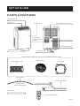
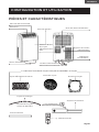
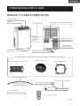
PARTS & FEATURES
Power cord holder
Power Cord
Condensation Drain
Dehumidication Drain
Control Panel
Front Panel
Louver
Air Exhaust Hose Hose Inlet
Hose Outlet
Drain Hose
3.3 feet long
0.6 inch diameter
Remote Control
Foam Seal
2 Locking Screws
SET UP & USE
Window Bracket
Hose outlet and inlet are pre-assembled to the hose
Page 9
Air Exhaust
Hose Housing
Outlet
Caster Wheels

Page 10
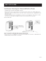
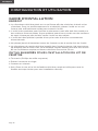
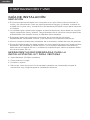
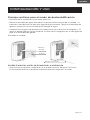
INSTALLATION GUIDE
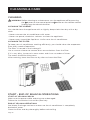
LOCATION
• The air conditioner should be placed on a rm oor to minimize noise and
vibration. For safe and secure positioning, place the unit on a smooth, level
oor strong enough to support the unit.
• The unit has casters to aid placement, but it should be rolled on smooth, at
surfaces. Use caution when rolling on carpet surfaces. Do not attempt to roll
the unit over objects.
• The unit must be placed within reach of a properly rated grounded socket.
• Never place any obstacles around the air inlet or outlet of the unit.
• A removal air-conditioner shall be installed in the at and empty place all
around. Don’t block the air outlet, and the required distance around should
be at least 80cm required distance above should be at least 50cm.
SUGGESTED TOOLS FOR WINDOW KIT INSTALLATION
• Screwdrivers (medium size Phillips)
• Tape measure or ruler
• Knife or scissors
• Saw (In the event that the window kit needs to be cutdown in size because the
window is too narrow for direct installation)
SET UP & USE

Page 11
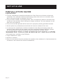
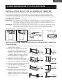
WINDOW SLIDER KIT INSTALLATION
Your window slider kit has been designed to t most standard “Vertical” and
“Horizontal” window applications; however, it may be necessary for you to
improvise/modify some aspect of the installation procedures for certain types of
windows. Minimum and maximum window openings:
MAXIMUM: 48.4” (123 cm) MINIMUM: 26.5” (67.5 cm)
NOTE: · A plastic locking pin is holding the window slider kit together during shipment. Prior
to installation, remove plastic locking pin, adjust to desired length and use provided
metal locking screws to secure.
NOTE: · If the window opening is less than 26.5”, the minimum length of the window slider
kit, cut the one with a hole in it short to t for the window opening. Never cut out
the hole in window slider kit.
SET UP & USE
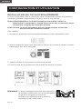
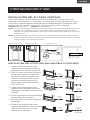
DOUBLE-HUNG SASH/SLIDING CASEMENT WINDOW
INSTALLATION
1. Cut the foam seal (adhesive type) to the proper length and attach it to the
window sash.
Horizontal Window Vertical Window Window Slider Kit
Window slider kit can be secured by
inserting the locking screw
Cut on opposite
side of hole
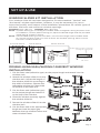
2. Attach the window slider kit to the
window sash. Adjust the length of
the window slider kit according to
the width of window. Shorten the
adjustable window kit if the width
of window is less than 26.5”.
3. Cut the foam seal (adhesive type)
to the proper length and attach it
on the top of the window.
4. Close the window securely against
the window slider kit.
5. Secure the window slider kit to the
window sash.
6. Cut the foam seal to an appropriate
length and seal the open gap
between the top window frame and
outer window frame.

Page 12
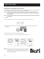
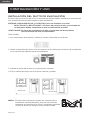
EXHAUST HOSE INSTALLATION
The air exhaust hose and hose inlet must be installed or removed from the portable
air conditioner in accordance with the way it is being used:
COOL, DEHUMIDIFY and HEAT (Heat model BPACT12HWT and BPACT14HWT
only): Air exhaust hose and hose inlet should be connected to the portable
air conditioner.
FAN: Air exhaust hose and hose inlet should be disconnected from the portable air
conditioner.
To install:
1. The hose outlet and inlet are pre-assembled to the air exhaust hose.
2. Align the hose inlet with the slots over the air exhaust hose housing outlet to
assemble.
3. Insert the hose outlet into the window panel.
4. Afx the hose outlet into the window slider kit and seal.
NOTE: The exhaust hose can be compressed or extended
moderately, but it is desirable to keep the length to a
minimum. Also make sure that the hose does not
have any sharp bends.
SET UP & USE

Page 13
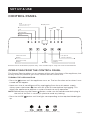
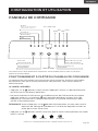
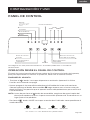
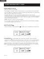
CONTROL PANEL
SET UP & USE
Cool
Fan
Display Area
AUTOLOW MED HIGH
Dehumidify
Heat
(Heat models BPACT12HWT
and BPACT14HWT only)
Mode Selection
Button
Fan Speed
Selection Button
Increase Temp
Button
ON/OFF
Decrease Temp
Button
Pictures are for illustration purpose only. Your model may or may not have all the features.
OPERATING FROM THE CONTROL PANEL
The Control Panel enables you to manage all the main functions of the appliance, but
to fully utilize its potential, you must use the remote control unit.
TURNING THE APPLIANCE ON
• Press the button until the appliance turns on. The last function active when it was
turned o will appear.
• Never turn the air conditioner o by unplugging from the main power supply.
Always press the button , then wait for a few minutes before unplugging. This
allows the appliance to perform a cycle of checks to verify operation.
NOTE: Before pressing the Power button, make sure the condensate drain plug in
the rear of the unit is securely in place to avoid any leaking.
• Press the MODE button until the light corresponding to the required Mode lights
up.
*Heat models BPACT12HWT and BPACT14HWT only

Page 14
SET UP & USE
COOL MODE
Ideal for hot weather when you need to cool and dehumidify the room. To set
operation of the appliance correctly, press the Temp Up or Temp Down
buttons until the desired temperature is displayed.
Then select the fan speed by pressing the Fan Speed Button until the light
corresponding to the required fan speed lights up:
HIGH: The fan operates at maximum to reach the required temperatures as rapidly as
possible.
MED: Reduces Fan noise level but still maintains a good level of comfort.
LOW: For quiet operation.
AUTO: The appliance automatically selects the most suitable fan speed in relation to
the temperature set on the digital display.
DEHUMIDIFY MODE
Ideal for reducing humidity in spring and autumn, during rainy spells or in damp
rooms, etc.
Exhaust hose attachment is recommended for more eective dehumidification but
not required.
In dehumidify mode, the fan speed is automatically set to a low speed and cannot be
adjusted.
When an error code appears on the display screen on the control panel “E2”, the unit
will have to be drained.
FAN MODE
Press the mode key until the fan mode indicator lights up, indicating that the fan
function is selected.
Press the speed button to select the appropriate fan speed.
HEAT MODE (Heat models BPACT12HWT and BPACT14HWT only)
Press the MODE button until the HEAT mode indicator light appears. Select the
target temperature by pressing the or button until the corresponding value is
displayed. (Temperature range is 61oF-88oF (16oC-31oC)
Then select the fan speed by pressing the Fan Speed Button until the light
corresponding to the desired fan speed lights up: HIGH, MED, LOW, AUTO.
NOTE: At the beginning of this mode, you may have to wait a few seconds before the
appliance starts to give out hot air.
When an error code appears on the display screen “E4” in HEAT mode, the unit will
have to be drained.
NOTE: AUTO speed can only be selected using the control panel.

Page 15
SET UP & USE
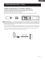
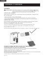
OPERATING FROM THE REMOTE CONTROL
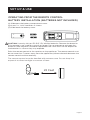
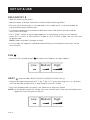
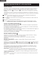
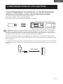
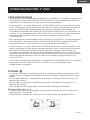
BATTERY INSTALLATION (BATTERIES NOT INCLUDED)
(1) Slide open the battery compartment cover.
(2) Insert 2 × “AAA” batteries as shown.
(3) Slide back the battery cover.
CAUTION: Use only AAA or IEC R03 1.5V alkaline batteries. Remove the batteries
if the remote is not used for a month or longer. Do not attempt to recharge the
batteries. Both batteries should be replaced at the same time. Do not dispose of
the batteries in a fire as they may explode.
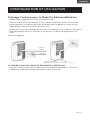
Point the remote control at the receiver on the appliance. The remote control must
be no more than 7 meters away from the appliance (without obstacle between the
remote control and the receiver).
The remote control must be handled with extreme care. Do not drop it or
expose it to direct sunlight or sources of heat.
23 Feet

Page 16
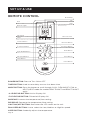
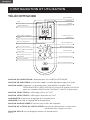
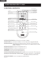
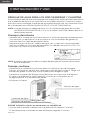
REMOTE CONTROL
SET UP & USE
POWER BUTTON: Press to Turn ON or OFF
TIMER BUTTON: Used to set a delay start or shut down time.
MODE BUTTON: Press the button to scroll through COOL, DEHUMIDIFY, FAN or
HEAT (HEAT mode for models BPACT12HWT and BPACT 14HWT
only)
oC SELECTOR BUTTON: Celsius Display ON
oF SELECTOR BUTTON: Fahrenheit Display ON
INCREASE: Increase the temperature/time setting.
DECREASE: Decrease the temperature/time setting.
LIGHT ON/OFF BUTTON: Illuminates the LED screen on the unit.
FAN SPEED BUTTON: Use to select the Low, Medium or High fan speed.
SLEEP BUTTON: Gradually adjusts the temperature.
Remote Signal
Cool
Dehumidify
Fan
Timer Selection
oF Selector Button
Increase Button
oC Selector Button
Light On/O Button
Fan Speed Button
Sleep Button
Fan Speed
Sleep
Decrease Button
Mode Button
Timer Button
Power Button
Heat
(Heat models BPACT12HWT and
BPACT14HWT only)

Page 17
SET UP & USE
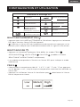
LED Display Indicators
Fan speed
Dehumidify mode Swing
Fan mode Timer on
Heat mode
Heat models
BPP08HWTB and
BPP10HWTB only Sleep
Display temp. or
hours
Fahrenheit or
Celsius.
Timer o
POWER BUTTON
• Press to Turn Air Conditioner ON or OFF. Press LED button to illuminate the
LED screen on the unit.
•
Will show on the remote LED screen when buttons are pressed to show that
the remote control is sending a signal to the air conditioner.
MODE BUTTON
• Press the mode button to scroll through COOL , DEHUMIDIFY , FAN ,
HEAT (Heat models BPACT12HWT and BPACT14HWT only).
• The corresponding symbol will illuminate on the LED display to indicate which
mode is selected.
COOL
• Select the target temperature 61˚F–88˚F (16˚C – 31˚C) by pressing the + or -
buttons until the desired temperature is displayed on the LED screen.
• Press the Fan Speed Button to select Low, Medium, or High Speed.
BPACT12HWT and
BPACT14HWT only
Cool mode

Page 18
SET UP & USE
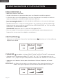
DEHUMIDIFY
• Ideal for reducing humidity.
• Keep window and door closed for the best dehumidifying eect.
• Exhaust hose attachment is not required in this mode but it is recommended for
more eective dehumidification.
• It is recommended that the dehumidification drain and drain hose be used for
continuous drainage.
• FULL TANK - When an error code appears on the display screen on the control
panel “E2” in COOL or DEHUMIDIFY mode, or “E4” in HEAT mode, the unit will have
to be drained.
NOTE: Refer to Water Drainage section.
• In this mode, fan speed is selected automatically by the appliance and can not be
set manually.
FAN
• Press the Fan Speed Button to select Low, Medium or High Speed.
HEAT (Heat models BPACT12HWT and BPACT14HWT only)
• Select the target temperature 61˚F–88˚F (16˚C–31˚C) by pressing the + or - buttons
until the desired temperature is displayed on the LED screen.
• Press the speed button to select Low, Medium or High fan speed.
NOTE: At the beginning of this mode, you may have to wait a few seconds before the
appliance starts to give out hot air.

Page 19
SET UP & USE
TIMER
• To set the AUTO STOP timer. When the unit is ON, press the TIMER button. The
TIME ON/OFF symbol on the remote LCD display will blink.
• Press the + or - button to select the AUTO TIME by 1 hour increments, up to 24
hours. The Remote LCD Display will indicate the selected time. Press the TIMER
button again to set the selected time. There will be a steady TIME ON/OFF symbol
on the remote LCD display and the TIMER indicator light will be illuminated on the
control panel of the unit to show that the AUTO STOP program is initiated.
• To set the AUTO START timer. When the unit is OFF, press the TIMER button. The
TIME ON/OFF symbol on the remote LCD display will blink.
• Press the + or - button to select the AUTO TIME by 1 hour increments, up to 24
hours. The Remote LCD Display will indicate the selected time. Press the TIMER
button again to set the selected time. There will be a steady TIME ON/OFF symbol
on the remote LCD display and the TIMER indicator light will be illuminated on the
control panel of the unit to show that the AUTO START program is initiated.
• Pressing the POWER button or the TIMER button will cancel the AUTO START/STOP
timed program and the timer indicator light will not be illuminated.
SLEEP
• The SLEEP function gradually adjusts the temperature of the rooms to provide a
comfortable environment. Press the SLEEP button to activate.
• In COOL mode, the temperature will increase 2°F after an hour and 4°F after 2
hours.
• In HEAT mode, the temperature will decrease 2°F after an hour and 4°F after 2
hours.
• To cancel this setting press the SLEEP button again.
°C / °F SELECTOR BUTTONS
• When the appliance is powered on, press the °F selector button to display the
temperature in Fahrenheit.
• Press the °C selector button to display the temperature in Celsius.
°F

Page 20
SET UP & USE
WATER DRAINAGE FOR COOL AND HEAT MODES
This air conditioner is equipped with auto water evaporation so the water compartment
would not typically fill in cooling or heating mode unless there is high humidity. Water
drainage will generally only be required at the end of the season for these modes. (see
START-END OF SEASON OPERATIONS).
NOTE: When an error code appears on the display screen on the control panel “E2” in
COOL or DEHUMIDIFY mode, or “E4” in HEAT mode, the unit will have to be
drained.
Intermittent Draining
• Unplug the unit from the power source. Carefully move the unit to a drain area
over your basement floor or drip pan (not included). Remove the bottom drain
cap.
• Let the water drain away and replace the drain cap. Restart the machine until the
error codes E2 or E4 disappears. If the error repeats, call for service.
NOTE: Be sure to reinstall the bottom drain plug before using the unit.
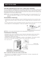
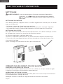
Continuous Draining
• Unplug the unit from the power source. Remove the bottom drain cap. While
doing this operation, some residual water may spill. Have a drip pan (not
supplied) to collect the water.
• Connect the drain hose (supplied) as shown in the diagram. The water can be
continuously drained through the hose into a floor drain or drip tray.
• Turn on the unit.
Drain outlet
Drain cap
Drain hose
WAIT 3 MINUTES BEFORE RESUMING OPERATION
• After the unit has stopped, it cannot be restarted for 3 minutes. Operation will
automatically restart after 3 minutes.
La page charge ...
La page charge ...
La page charge ...
La page charge ...
La page charge ...
La page charge ...
La page charge ...
La page charge ...
La page charge ...
La page charge ...
La page charge ...
La page charge ...
La page charge ...
La page charge ...
La page charge ...
La page charge ...
La page charge ...
La page charge ...
La page charge ...
La page charge ...
La page charge ...
La page charge ...
La page charge ...
La page charge ...
La page charge ...
La page charge ...
La page charge ...
La page charge ...
La page charge ...
La page charge ...
La page charge ...
La page charge ...
La page charge ...
La page charge ...
La page charge ...
La page charge ...
La page charge ...
La page charge ...
La page charge ...
La page charge ...
La page charge ...
La page charge ...
La page charge ...
La page charge ...
La page charge ...
La page charge ...
La page charge ...
La page charge ...
La page charge ...
La page charge ...
La page charge ...
La page charge ...
La page charge ...
La page charge ...
La page charge ...
La page charge ...
La page charge ...
La page charge ...
-
 1
1
-
 2
2
-
 3
3
-
 4
4
-
 5
5
-
 6
6
-
 7
7
-
 8
8
-
 9
9
-
 10
10
-
 11
11
-
 12
12
-
 13
13
-
 14
14
-
 15
15
-
 16
16
-
 17
17
-
 18
18
-
 19
19
-
 20
20
-
 21
21
-
 22
22
-
 23
23
-
 24
24
-
 25
25
-
 26
26
-
 27
27
-
 28
28
-
 29
29
-
 30
30
-
 31
31
-
 32
32
-
 33
33
-
 34
34
-
 35
35
-
 36
36
-
 37
37
-
 38
38
-
 39
39
-
 40
40
-
 41
41
-
 42
42
-
 43
43
-
 44
44
-
 45
45
-
 46
46
-
 47
47
-
 48
48
-
 49
49
-
 50
50
-
 51
51
-
 52
52
-
 53
53
-
 54
54
-
 55
55
-
 56
56
-
 57
57
-
 58
58
-
 59
59
-
 60
60
-
 61
61
-
 62
62
-
 63
63
-
 64
64
-
 65
65
-
 66
66
-
 67
67
-
 68
68
-
 69
69
-
 70
70
-
 71
71
-
 72
72
-
 73
73
-
 74
74
-
 75
75
-
 76
76
-
 77
77
-
 78
78


BLACK DECKER BPACT08WT PORTABLE AIR CONDITIONER Remote Control Manuel utilisateur
- Taper
- Manuel utilisateur
dans d''autres langues
Documents connexes
Autres documents
-
commercial cool CPT05WTB Manuel utilisateur
-
Danby DPAC 12099 Manuel utilisateur
-
-
-
-
-
Royal Sovereign ARP-9009TL Manuel utilisateur
-
BLACK+DECKER BLACK+DECKER BHDC201 Portable Space Heater Manuel utilisateur
-
Woods WAC1202G Manuel utilisateur
-
Rowenta VU6770 Mode d'emploi