Toro CCR 2400 Snowthrower Manuel utilisateur
- Catégorie
- Souffleuses à neige
- Taper
- Manuel utilisateur
Ce manuel convient également à

Operator’s Manual Manuel de l’Utilisateur
FORM NO. 3321–376 Rev A
CCR
2400 GTS
CCR
2500 GTS
CCR
3000 GTS
Snowthrower
Model No. 38409–9900001 & Up
Model No. 38414–9900001 & Up
Model No. 38422–9900001 & Up
Model No. 38424–9900001 & Up
Model No. 38432–9900001 & Up
Model No. 38437–9900001 & Up
CCR
2400 GTS
CCR
2500 GTS
CCR
3000 GTS
Déneigeuse
Modèle No. 38409–9900001 et suivants
Modèle No. 38414–9900001 et suivants
Modèle No. 38422–9900001 et suivants
Modèle No. 38424–9900001 et suivants
Modèle No. 38432–9900001 et suivants
Modèle No. 38437–9900001 et suivants

The engine exhaust from this product
contains chemicals known to the State of
California to cause cancer, birth defects,
or other reproductive harm.
WARNING:
Les gaz d’échappement du moteur de ce
produit contiennent des produits
chimiques reconnus dans l’état de
Californie comme étant cancérigènes,
responsables de malformations
congénitales et dangereux pour les
organes reproducteurs.
AVERTISSEMENT:

The Toro Company – 1998
All Rights Reserved
Printed in USA
i
Figures
637
English
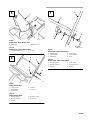
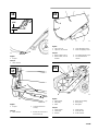
1. Model
and serial number decal
Français
1.
Numéros de modèle et de série
637
1
2
3
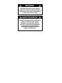
English
(Unit shown on right side)
1.
Short spacer
2.
Long spacer
3. Pushnut
Français
(La déneigeuse est montrée basculée sur son côté droit)
1.
Entretoise courte
2.
Entretoise longue
3. Écrou-poussoir
1 2

ii
m-3277
1
4
5
2
3
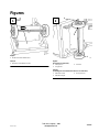
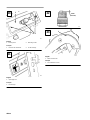
English
Models 38409 & 38414
1.
Chute ring
2.
Discharge chute
3.
Chute handle
4.
Carriage bolt
5.
Lock nut
Français
Modèles 38409 & 38414
1.
Couronne d’éjecteur
2. Ejecteur
3.
Poignée d’orientation
4.
Boulon de carrossier
5. Écrou-frein
893
635
3
1
2
4
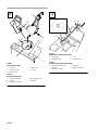
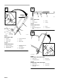
English
Models 38422 , 38424, 38432 & 38437
1.
Chute crank
2.
Mounting bracket
3. Gear
4.
Plastic bushing
Français
Modèles 38422 , 38424, 38432 & 38437
1.
Manivelle d’orientation de
l’éjecteur
2.
Support de montage
3. Engrenage
4.
Bague en plastique
3 4

iii
1
2
636
English
Models 38422 , 38424, 38432 & 38437
1.
Chute ring
2.
Discharge chute
Français
Modèles 38422 , 38424, 38432 & 38437
1.
Couronne d’éjecteur
2. Ejecteur
2
1
4
3
m-2707
5
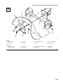
English
Models 38409 & 38414
1.
Lower handle
2.
Upper handle
3.
Handle bolt
4. Eyebolt
5.
Lock nut
Français
Modèles 38409 & 38414
1.
Manche inférieur
2.
Manche supérieur
3. Boulon
4.
Boulon à anneau
5. Écrou-frein
4
3
m-2707
5
2
1
6
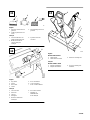
English
Models 38422 , 38424, 38432 & 38437
1.
Lower handle
2.
Upper handle
3.
Handle lock
4.
Cable guide
5.
Curved washer
6. Knob
Français
Modèles 38422 , 38424, 38432 & 38437
1.
Manche inférieur
2.
Manche supérieur
3. T
ige en U
4. Guide–câble
5.
Rondelle convexe
6. Bouton
5
6
7

iv
m-2708
1/16–1/8”
2
4
3
1
5
6
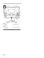
English
Models 38409 & 38414
1. Eyebolt
2.
Control cable
3.
Spring cover
4.
Control bar bracket
5. T
op hole
6.
Bottom hole
Français
Modèles 38409 & 38414
1.
Boulon à anneau
2.
Câble de commande
3. Cache-ressort
4.
Support de barre de
commande
5. T
rou supérieur
6. T
rou inférieur
897
43 21
English
Models 38409 & 38414
1. Spring
2.
Cable adjuster
3. Cable
4.
Z fitting
Français
Modèles 38409 & 38414
1. Ressort
2.
Dispositif de réglage du
câble
3. Câble
4.
Crochet en Z
1
2
3
1/16–1/8”
m–4017/4012
4
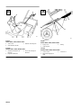
English
Models 38422 , 38424, 38432 & 38437
1.
Cable guide
2.
Control bar bracket
3.
Rear hole
4.
Forward hole
Français
Modèles 38422 , 38424, 38432 & 38437
1. Guide–câble
2.
Support de barre de
commande
3. T
rou arrière
4. T
rou avant
8 9
10

v
111
1
2
3
English
1.
Add oil to small amount of
gasoline
2.
Install cap and shake can
to mix
3.
Add remaining amount of
gasoline
Français
1. V
ersez l’huile dans une
petite quantité d’essence
2.
Mettez le bouchon et
secouez bien pour
mélanger
3.
Ajoutez le reste de
l’essence
1
2
3
5
4
6
642
English
1.
Key switch
2. Primer
3.
Recoil start
4. Choke
5.
Elec. start button*
6.
Cord connection*
*
ELEC. ST
AR
T MODEL
Français
1.
Clé de contact
2. Amorceur
3. Lanceur
4. Étrangleur
5.
Bouton du démarreur
électrique*
6.
Raccord du cordon*
*
MODELE A
DEMARRAGE
ELECTRIQUE
m-3278
3
1
2
English
Models 38409 & 38414
1.
Chute handle
2.
Chute deflector handle
3.
Deflector mounting nuts
Français
Modèles 38409 & 38414
1.
Poignée d’orientation
2.
Poignée du déviateur
3.
Écrous de montage du
déviateur
11
12
13

vi
2
3
1
629
English
Models 38422 , 38424, 38432 & 38437
1.
Chute crank
2.
Chute deflector handle
3.
Deflector mounting nuts
Français
Modèles 38422 , 38424, 38432 & 38437
1.
Manivelle d’orientation de
l’éjecteur
2.
Poignée du déviateur
3.
Écrous de montage du
déviateur
1
2
630
3
English
Models 38422 , 38424, 38432 & 38437
1.
Spring cover
2.
Cable adjuster
3.
Z fitting
Français
Modèles 38422 , 38424, 38432 & 38437
1. Cache-ressort
2.
Dispositif de réglage du
câble
3.
Crochet en Z
14 15

vii
634
1/16”
1
English
1. Scraper
Français
1.
Lame racleuse
2
644
1
English
1. Scraper 2.
Carriage bolts & lock
nuts (3)
Français
1.
Lame racleuse
2.
Boulons de carrossier et
écrous-freins (3)
1
2
3
4
631
English
1.
Cap screw
, nut
2. Capscrew
, nut, washer
3.
Long self tapping screw
4.
Short self tapping screws
Français
1.
Boulon à tête et écrou
2.
Boulon à tête, écrou et
rondelle
3. Vis
autotaraudeuse longue
4. Vis
autotaraudeuses
courtes
4
2
1
6
3
5
626
English
1.
Engine pulley
2.
Idler pulley
3. Roller
4.
Brake arm assembly
5.
Rotor pulley
6.
Belt guide
Français
1.
Poulie moteur
2.
Poulie folle
3. Rouleau
4.
Unité de frein
5.
Poulie du rotor
6. Guide-courroie
16
17
18
19

viii
643
1
2
English
1.
Control panel
2.
Mounting screws
Français
1.
Panneau de commande
2. V
is de montage
1
628
English
1.
Spark plug wire
Français
1.
Fil de bougie
0.032”
(0.81 mm)
110
1
English
1. W
ear indicator hole
Français
1. T
rou indicateur d’usure
20
21
22
23

ix
1
2
3
4
4
5
6
7
8
680
English
1.
Rotor blade (2)
2.
Rotor half (2)
3. T
orx screw (8)
4.
Locknut (13)
5.
Hex–head capscrew (4)
6.
Spacer (4)
7.
Auger shaft assembly
8.
Hex–head screw
Français
1.
Lame du rotor (2)
2.
Plaque d’acier (2)
3. V
is T
orx (8)
4.
Écrou-frein (13)
5.
Boulon à tête hexagonale (4)
6.
Entretoise (4)
7.
Arbre du rotor
8. V
is six pans
24

x
1
2
3
681
English
1.
Thin layer
2.
Thick layer
3. W
ear indicator hole
Français
1.
Couche mince
2.
Couche épaisse
3. T
rou indicateur d’usure
25

EN–1
Contents
Page
Introduction 1.
. . . . . . . . . . . . . . . . . . . . . . . . . . .
Safety 2
. . . . . . . . . . . . . . . . . . . . . . . . . . . . . . . . .
Before Operating 2
. . . . . . . . . . . . . . . . . . . .
While Operating 3
. . . . . . . . . . . . . . . . . . . . .
Maintaining Snowthrower 3
. . . . . . . . . . . . .
Safety and Instruction Decals 4
. . . . . . . . . .
Assembly 5
. . . . . . . . . . . . . . . . . . . . . . . . . . . . . .
Install Wheels
5
. . . . . . . . . . . . . . . . . . . . . . .
Install Discharge Chute And Chute Handle 5
Install Chute Crank 5
. . . . . . . . . . . . . . . . . .
Install Dischar
ge Chute
5
. . . . . . . . . . . . . . .
Install Handle 5
. . . . . . . . . . . . . . . . . . . . . . .
Install Control Cable 6
. . . . . . . . . . . . . . . . .
Install Control Cable 6
. . . . . . . . . . . . . . . . .
Before Starting 6
. . . . . . . . . . . . . . . . . . . . . . . . . .
Mix Gasoline And Oil 6
. . . . . . . . . . . . . . . .
Operation 7
. . . . . . . . . . . . . . . . . . . . . . . . . . . . . .
Starting/Stopping Engine 7
. . . . . . . . . . . . . .
Operating Tips 8
. . . . . . . . . . . . . . . . . . . . . .
Maintenance 9
. . . . . . . . . . . . . . . . . . . . . . . . . . . .
Adjusting Control Bar 9
. . . . . . . . . . . . . . . .
Draining Gasoline 10
. . . . . . . . . . . . . . . . . . .
Replacing Scraper 10
. . . . . . . . . . . . . . . . . . .
Replacing Drive Belt 10
. . . . . . . . . . . . . . . . .
Replacing Spark Plug 11
. . . . . . . . . . . . . . . . .
Adjusting Carburetor 11
. . . . . . . . . . . . . . . . .
Replacing Rotor Blades
11
. . . . . . . . . . . . . . .
Storage 12
. . . . . . . . . . . . . . . . . . . . . . . . . . . . . . . .
The Toro Starting Guarantee 13
. . . . . . . . . . . . . . .
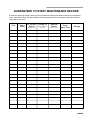
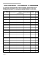
Guaranteed To Start Maintenance Record 15
. . . . . . .
Federal Emission Control Warranty Statement 16
.
Warranty 19
. . . . . . . . . . . . . . . . . . . . . . . . . . . . . . .
Introduction
Thank you for purchasing a Toro product.
All of us at Toro want you to be completely satisfied
with your new product, so feel free to contact your
local Authorized Service Dealer for help with service,
genuine Toro parts, or other information you may
require.
Whenever you contact your Authorized Service
Dealer or the factory, always know the model and
serial numbers of your product. These numbers will
help the Service Dealer or Service Representative
provide exact information about your specific
product. You will find the model and serial number
decal located in a unique place on the product
(Fig. 1).
For your convenience, write the product model and
serial numbers in the space below.
Model No:
Serial No.
Read this manual carefully to learn how to operate
and maintain your product correctly. Reading this
manual will help you and others avoid personal injury
and damage to the product. Although Toro designs,
produces and markets safe, state-of-the-art products,
you are responsible for using the product properly
and safely. You are also responsible for training
persons who you allow to use the product about safe
operation.
The Toro warning system in this manual identifies
potential hazards and has special safety messages that
help you and others avoid personal injury, even death.
DANGER, WARNING and CAUTION are signal
words used to identify the level of hazard. However,
regardless of the hazard, be extremely careful.
DANGER signals an extreme hazard that will cause
serious injury or death if the recommended
precautions are not followed.

EN–2
WARNING signals a hazard that may cause serious
injury or death if the recommended precautions are
not followed.
CAUTION signals a hazard that may cause minor or
moderate injury if the recommended precautions are
not followed.
Two other words are also used to highlight
information. “Important” calls attention to special
mechanical information and “Note” emphasizes
general information worthy of special attention.
The left and right side of the machine is determined
by standing behind the handle in the normal
operator’s position.
Safety
T
o ensur
e maximum safety, best performance, and
to gain knowledge of the product, it is essential
that you or any other operator of the snowthrower
read and understand the contents of this manual
before the motor is ever started. Pay particular
attention to the safety alert symbol which
means CAUTION, W
ARNING OR DANGER —
“personal safety instruction.” Read and
understand the instruction because it has to do
with safety. Failure to comply with instruction
may result in personal injury.
This snowthrower is designed and tested to offer safe
and effective service, provided it is operated in strict
accordance with the following Safety Instructions.
Failure to comply with the following instructions
MA
Y RESUL
T IN PERSONAL INJUR
Y.
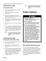
Before
Operating
1. Read and understand the contents of this manual
before operating the snowthrower. Become
familiar with all controls and know how to stop
engine and snowthrower quickly.
2. Never allow children to operate the
snowthrower. Adults should operate the
snowthrower only after reading this manual.
3. Keep everyone, especially children and pets,
away from snowthrower and area of operation.
4. Inspect area thoroughly where snowthrower will
be used. Remove doormats, sleds, boards, sticks,
wire and any other foreign objects which might
be picked up and thrown by the snowthrower.
5. Keep all shields and safety devices in place. If a
shield, safety device or decal is illegible,
damaged or lost, repair or replace it before
beginning operation. Also, tighten any loose
nuts, bolts or screws.
6. Wear adequate winter clothing and rubber boots
that will ensure proper footing on slippery
surfaces. Do not wear loose–fitting clothing that
could possibly get caught in moving parts.
7. Always wear safety glasses or eye shields during
operation or while performing an adjustment or
repair to protect eyes from foreign objects that
may be thrown from the machine.
8. Fill fuel tank with gasoline before starting the
engine. A
void spilling any gasoline. Because
fuel is highly flammable, handle it carefully. DO
NOT SMOKE WHILE HANDLING
GASOLINE.
A. Use an approved gasoline container.
B. Fill fuel tank outdoors, not indoors.
NEVER ADD FUEL T
O AN ENGINE
THAT IS RUNNING OR HOT. Engine
must be cool to reduce potential fire hazard.
C. Open doors if engine will be started in the
garage because exhaust fumes are
dangerous and could possibly be deadly. Do
not run engine indoors.
D. Wipe up any spilled gasoline. Reinstall
gasoline container cap and snowthrower
fuel tank cap securely before starting the
engine.
9. Allow engine to warm up outdoors before
operating. Do not run engine indoors.

EN–3
While
Operating
10. Use only a UL listed extension cord (16 gage
wire minimum) for use with the electric start
model. Do not plug the extension cord into
outlet while standing in water or when hands are
wet. Do not use cord if gasoline has been spilled.
If extension cord is damaged, replace
immediately (Part No. 28–9170).
11. Never direct discharge toward or operate
snowthrower near bystanders, glass enclosures,
automobiles and trucks, window wells or a
drop–off. Never allow anyone in front of
snowthrower.
12. Keep people and pets a safe distance away from
the snowthrower and area of operation.
13. Operate the snowthrower only when there is
good visibility or light. Always maintain secure
footing and balance and keep a firm grip on the
handle. Walk; never run.
14. DO NOT USE SNOWTHROWER ON A
ROOF.
15. Be attentive when using the snowthrower, and
stay alert for holes in the terrain and other
hidden hazards.
16. STAY AWAY FROM DISCHARGE
OPENING WHILE OPERA
TING THE
SNOWTHROWER. Keep face, hands, feet, and
any other part of your body or clothing away
from concealed, moving, or rotating parts.
17. Never clear snow off steep slopes or across the
faces of slopes. Exercise extreme caution when
changing direction on slopes.
18. Do not overload the snowthrower by clearing
snow at too fast a rate.
19. Use extreme caution when crossing or operating
snowthrower on walks, roads or gravel or
crushed rock drives. Refer to Operating Tips,
page 7, item 4 for correct operating procedure.
20. If a foreign object is hit or snowthrower vibrates
abnormally, stop engine by turning key to OFF
and wait for all moving parts to stop. Check
snowthrower immediately for possible damage,
an obstruction or loose parts. Vibration is
generally a sign of trouble. Repair any damage
before operating snowthrower again.
21. Before adjusting, cleaning, repairing or
inspecting the snowthrower, or before
unclogging the discharge chute, stop engine by
turning key to OFF and wait for all moving parts
to stop. Disconnect the spark plug wire and
keep the wire away from the plug to prevent
someone from accidentally starting the unit. Do
not make adjustments while engine is running.
22.
WHENEVER YOU LEA
VE THE
OPERA
TING POSITION, ST
OP ENGINE
BY TURNING KEY T
O OFF
. REMOVE
KEY FROM SWITCH IF UNIT WILL BE
UNATTENDED.
23. Let snowthrower run for a few minutes after
clearing snow so moving parts do not freeze.
Maintaining
Snowthrower
24. REMOVE KEY FROM SWITCH when storing
snowthrower. Store key in a memorable place.
25. Never store snowthrower with fuel in fuel tank
inside a building where ignition sources such as
an open flame, sparks, hot water and space
heaters, and clothes dryers are present. Allow
engine to cool before storing.
NEVER ST
ORE
SNOWTHROWER IN HOUSE (LIVING
AREA) OR BASEMENT BECAUSE
GASOLINE AND FUMES ARE HIGHL
Y
FLAMMABLE, EXPLOSIVE, AND
DANGEROUS IF INHALED.
26. Perform only those maintenance instructions
described in this manual. Remove key from
switch before performing maintenance
procedures to prevent the possibility of
accidental starting. If major repairs are ever
needed, contact your local Authorized TORO
Service Dealer for assistance.

EN–4
27. Keep snowthrower in safe operating condition
by keeping nuts, bolts, and screws tight. Check
all fasteners frequently to ensure they are tight.
28. Maintain or replace safety and instruction labels,
as necessary
.
29. To ensure best performance and safety, purchase
genuine TORO replacement parts and
accessories to keep your TORO all TORO.
NEVER USE “WILL FIT” REPLACEMENT
PAR
TS AND ACCESSORIES.
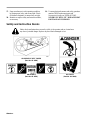
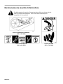
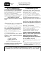
Safety
and Instruction Decals
Safety decals and instructions are easily visible to the operator and are located near
any area of potential danger. Replace any decal that is damaged or lost.
ON INSIDE OF BEL
T COVER
(Part No. 60–9480)
ON CHUTE
(Part No. 94–2900)
ON HANDLE
(Part No. 66–6870)

EN–5
Assembly
Note: Determine left and right sides of the
snowthrower by standing in the normal
operator’s position behind the handles.
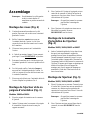
Install
Wheels (Fig. 2)
1. Carefully turn machine onto its left side. Place a
wood block under the left axle end.
2. Slide the short spacer and a wheel onto the right
axle end. The side of the wheel with six spokes
must face the center of the machine.
3. Slide a pushnut onto the end of the axle.
4. Using a hammer, strike the pushnut to seat the
nut FIRMLY
in place.
5. Turn the machine over on its right side so that
the left axle end is pointing up.
6. For the left side, slide the long spacer and a
wheel onto the left axle end. The side of the
wheel with six spokes must face the center of the
axle.
7. Place a wood block under the right axle end.
Repeat steps 3 and 4.
Install
Discharge Chute And
Chute Handle (Fig. 3)
Models 38409 & 38414
1. Place chute handle over chute ring.
2. Insert discharge chute between chute ring and
chute handle. Align holes.
3. Secure back of chute and handle to center hole in
chute ring with a carriage bolt and lock nut.
Position nut on outside of chute.
Note: Chute ring may be rotated to ease
assembly of dischar
ge chute.
4. Secure chute and handle to remaining holes in
chute ring and tighten all nuts SECURELY.
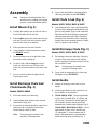
Install
Chute Crank (Fig. 4)
Models 38422, 38424, 38432 & 38437
1. Insert flattened end of chute crank through hole
in shroud while aligning mounting bracket with
holes in lower handle. Slowly rotate crank until
flattened end fits into hidden gear opening and
chute ring turns with crank. Make sure plastic
bushing is fully inserted into hole in mounting
bracket, then secure mounting bracket to handle
with (2) capscrews and locknuts.
Install
Discharge Chute (Fig. 5)
Models 38422, 38424, 38432 & 38437
1. Set discharge chute onto chute ring. Align hole
in back of chute with center hole in ring and
install a carriage bolt and sems locknut. Position
nut on outside of chute.
Note: Chute ring may be rotated to ease
assembly of dischar
ge chute.
2. Secure chute to remaining holes in chute ring
and tighten all nuts SECURELY.
Install
Handle
1. Remove tie securing control cable to lower
handle.
2. Position upper handle so that control bar is on
top of handle, not underneath it.
3. Models 38409 & 38414 – Secure upper handle
in place with (3) handle bolts, (1) eyebolt, and
(4) lock nuts. Use eyebolt to mount upper left
side of handle. Eyebolt must be positioned
perpendicular to handle when tightened (Fig. 6).
Models 38422, 38424, 38432 & 38437 – Secure
upper handle in place with (2) handle locks,
(1) cable guide, (2) curved washers and (2)
knobs. Cable guide must be perpendicular to
handle with loop facing out and up (Fig. 7).

EN–6
Install
Control Cable
Models 38409 & 38414
1. Route control cable through eyebolt on left side
of snowthrower (Fig. 8).
2. Hook spring to round hole at end of cable
adjuster (Fig. 9).
3. Route cable through elongated hole in cable
adjuster. Insert Z fitting on end of cable into 3rd
hole on cable adjuster (Fig. 9).
4. Slide spring cover over spring and cable adjuster.
Push spring end through hole at end of spring
cover (Fig. 8).
5. Hook spring into top hole of control bar bracket
(Fig. 8).
6. Move control bar back toward handle until slack
in cable is removed. The gap between the control
bar bracket and handle should be approximately
1/16”-1/8”. See insert, Figure 8. If an adjustment
is required, refer to Adjusting Control Bar,
page 9.
Note: The control cable must always have
slack in it when in the disengaged
position.
Install
Control Cable
Models 38422, 38424, 38432 & 38437
1. Route control cable through cable guide on left
side of snowthrower (Fig. 10).
2. Hook upper end of control cable in rear hole
(hole with arrow) in control bar bracket
(Fig. 10).
3. Move control bar back toward handle until slack
in cable is removed. The gap between bottom of
handle and stop on control bar (left hand side on
bottom of handle) should be approximately
1/16”-1/8”. See insert, Figure 10. If an
adjustment is required, refer to Adjusting
Control Bar, page 9.
Note: The control cable must always have
slack in it when in the disengaged
position.
Before
Starting
POTENTIAL
HAZARD
• In certain conditions gasoline is extremely
flammable and highly explosive.
WHAT CAN HAPPEN
• A fire or explosion from gasoline can burn
you, others, and cause property damage.
HOW TO AV
OID THE HAZARD
• Use a funnel and fill the fuel tank outdoors,
in an open area, when the engine is cold.
Wipe up any gasoline that spills.
• Do not fill the fuel tank completely full.
Add gasoline to the fuel tank until the level
is 1/4” to 1/2” (6 mm to 13 mm) below the
bottom of the filler neck. This empty space
in the tank allows gasoline to expand.
• Never smoke when handling gasoline, and
stay away from an open flame or where
gasoline fumes may be ignited by a spark.
• Store gasoline in an approved container
and keep it out of the reach of children.
• Never buy more than a 30-day supply of
gasoline.
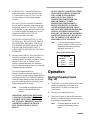
Mix
Gasoline And Oil (Fig. 1
1)
Use clean, fresh lead-free gasoline, including
oxygenated or reformulated gasoline, with an octane
rating of 85 or higher. To ensure freshness, purchase
only the quantity of gasoline that can be used in 30
days. Use of lead-free gasoline results in fewer
combustion chamber deposits and longer spark plug
life. Use of premium grade fuel is not necessary or
recommended.

EN–7
1. APPROVED OIL—For simplicity and best
engine performance, mix the contents of one
5.2–ounce bottle of Toro 50:1 T
wo–Cycle Oil
with two gallons of fresh, unleaded regular
gasoline.
Toro Two–Cycle Oil is specially formulated to
provide superior lubrication, make starting easy,
and prolong engine life. If Toro T
wo–Cycle Oil
is not available, mix two gallons of gasoline and
5.2 ounces of another high grade two–cycle oil
that has the NMMA or BIA–TCW III
certification printed on the label.
NEVER USE AUTOMOTIVE OIL (i.e. SAE
30, 10W30 etc.), TWO–CYCLE OIL THAT IS
NOT CERTIFIED NMMA/BIA–TCW III, OR
THE WRONG MIX RATIO BECAUSE THE
ENGINE CAN BE DAMAGED, AND IT
WOULD NOT BE COVERED BY THE TORO
WARRANTY.
2. Mixing Gasoline and Oil—Pour a half gallon of
gasoline into an approved gasoline container
(preferably plastic, not metal) and add the correct
amount of two–cycle oil. Reinstall cap on
gasoline container and shake the container to
mix oil and gas thoroughly. Remove cap and add
remaining amount of gasoline.
Toro also recommends that Toro
Stabilizer/Conditioner be used regularly in all
Toro gasoline powered products during operation
and storage seasons. Toro Stabilizer/Conditioner
cleans the engine during operation and prevents
gum–like varnish deposits from forming in the
engine during periods of storage.
Note: A fuel stabilizer/conditioner is most
effective when mixed with fresh
gasoline.
IMPORTANT
: NEVER USE METHANOL
,
GASOLINE CONT
AINING METHANOL
,
GASOHOL CONT
AINING MORE THAN
10% ETHANOL, PREMIUM GASOLINE,
OR WHITE GAS BECAUSE ENGINE
FUEL SYSTEM DAMAGE COULD
RESULT.
DO NOT USE FUEL ADDITIVES OTHER
THAN THOSE MANUF
ACTURED FOR
FUEL ST
ABILIZA
TION DURING
STORAGE SUCH AS TORO’S
ST
ABILIZER/CONDITIONER OR A
SIMILAR PRODUCT
. TORO’S
ST
ABILIZER/CONDITIONER IS A
PETROLEUM DISTILLA
TE BASED
CONDITIONER/ST
ABILIZER. T
ORO
DOES NOT RECOMMEND ST
ABILIZERS
WITH AN ALCOHOL BASE SUCH AS
ETHANOL, METHANOL OR ISOPROPYL.
ADDITIVES SHOULD NOT BE USED T
O
TRY TO ENHANCE THE POWER OR
PERFORMANCE OF MACHINE.
Note: Do not mix gasoline and oil in the
product fuel tank. Oil that is at room
temperature mixes easier and more
thoroughly than cold oil.
50:1
GAS/OIL Mixing Chart
U.S. GALLON
Gasoline Oil
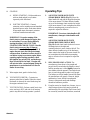
Operation
Starting/Stopping
Engine
(Fig. 12)
1. CONTROLS—Key switch, primer, recoil starter,
and electric start button are located on the
control panel. The choke is just below the
control panel.
2. Turn key to ON and pull choke out.
3. Cover hole in center of primer with thumb and
push twice. Additional primes may be necessary
in extremely cold temperatures.
Note: Choke and primer are usually not
necessary when starting a warm
engine.

EN–8
4. STARTING
A. RECOIL STARTING—Hold snowthrower
with one hand and pull recoil starter
vigorously with other hand.
B. ELECTRIC STARTING—Connect
extension cord to snowthrower and standard
household power outlet. Push starter button.
When engine starts, disconnect extension
cord from snowthrower and outlet.
IMPORTANT: Excessive running of the
electric starter could damage the starter due
to overheating. If you are having difficulty
starting the engine, ONL
Y TR
Y THIS
STAR
TING PROCEDURE TWICE. Run the
electric starter no more than 10 times at
intervals of 5 seconds ON, 5 seconds OFF. If
engine does not start after this first attempt,
wait more than 40 minutes to allow starter to
cool before trying to run starter again. Before
repeating engine starting procedure, check
that ignition key switch is ON, and make sure
there is fresh fuel in fuel tank. If engine still
will not start after a second attempt, bring the
snowthrower to an Authorized Toro Service
Dealer for servicing.
5. When engine starts, push in choke slowly.
6. TO START/STOP ROTOR—To start rotor,
squeeze control bar to handle. When the control
bar handle is released, the rotor blades stop, but
the engine continues to run.
7. TO STOP ENGINE—Release control bar to stop
rotor, turn key to OFF, and wait for all moving
parts to stop before leaving operator’s position.
Operating
T
ips
1. ADJUSTING
DISCHARGE CHUTE
(Models 38409 & 38414) (Fig. 13)
–Move the
chute handle left and right to adjust the direction
of the snow stream. The chute deflector handle
on top of the discharge chute controls the height
of the snow stream. Do not overtighten the chute
deflector mounting nuts so excessive force is
required to adjust the deflector.
IMPORTANT: Do not use chute handle to lift
snowthrower; damage to chute handle could
result.
ADJUSTING DISCHARGE CHUTE
(Models 38422, 38424, 38432 & 38437)
(Fig. 14)–Rotate chute crank clockwise to move
discharge chute to the right and
counterclockwise to move chute to the left. The
chute deflector handle on top of the discharge
chute controls the height of the snow stream. Do
not overtighten the chute deflector mounting
nuts so excessive force is required to adjust the
deflector.
2.
SELF–PROPELLING ACTION
–The
snowthrower clears down to the ground and
propels itself forward when the handle is raised
and the snowthrower is tilted slightly forward so
rotor blades strike the ground. The wheels do not
have to touch the ground in order to self-propel.
The further you tilt the handle forward, the faster
the snowthrower self-propels. However, height
and density of snow affects forward speed.
Always overlap each swath and discharge
downwind whenever possible.
3. Keep the area to be cleared free of stones, toys or
other foreign objects which may be picked up
and thrown by the rotor blades. Such items could
be covered by snowfall and, therefore, unnoticed
La page charge ...
La page charge ...
La page charge ...
La page charge ...
La page charge ...
La page charge ...
La page charge ...
La page charge ...
La page charge ...
La page charge ...
La page charge ...
La page charge ...
La page charge ...
La page charge ...
La page charge ...
La page charge ...
La page charge ...
La page charge ...
La page charge ...
La page charge ...
La page charge ...
La page charge ...
La page charge ...
La page charge ...
La page charge ...
La page charge ...
La page charge ...
La page charge ...
La page charge ...
La page charge ...
La page charge ...
La page charge ...
La page charge ...
La page charge ...
La page charge ...
La page charge ...
-
 1
1
-
 2
2
-
 3
3
-
 4
4
-
 5
5
-
 6
6
-
 7
7
-
 8
8
-
 9
9
-
 10
10
-
 11
11
-
 12
12
-
 13
13
-
 14
14
-
 15
15
-
 16
16
-
 17
17
-
 18
18
-
 19
19
-
 20
20
-
 21
21
-
 22
22
-
 23
23
-
 24
24
-
 25
25
-
 26
26
-
 27
27
-
 28
28
-
 29
29
-
 30
30
-
 31
31
-
 32
32
-
 33
33
-
 34
34
-
 35
35
-
 36
36
-
 37
37
-
 38
38
-
 39
39
-
 40
40
-
 41
41
-
 42
42
-
 43
43
-
 44
44
-
 45
45
-
 46
46
-
 47
47
-
 48
48
-
 49
49
-
 50
50
-
 51
51
-
 52
52
-
 53
53
-
 54
54
-
 55
55
-
 56
56


Toro CCR 2400 Snowthrower Manuel utilisateur
- Catégorie
- Souffleuses à neige
- Taper
- Manuel utilisateur
- Ce manuel convient également à
dans d''autres langues
Documents connexes
-
Toro CCR 3000 Snowthrower Manuel utilisateur
-
-
Toro 1800 Power Curve Snowthrower Manuel utilisateur
-
-
Toro CCR 3650 Snowthrower Manuel utilisateur
-
-
-
-
-